Page 5531 of 5621

WT-6
ROAD WHEEL
Revision: 2006 January2006 M35/M45
ROAD WHEELPFP:40300
InspectionNES000JO
ALUMINUM WHEEL
1. Check tires for wear and improper inflation.
2. Check wheels for deformation, cracks and other damage. If deformed, remove wheel and check wheel
runout.
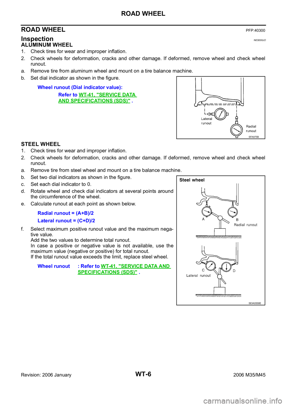
a. Remove tire from aluminum wheel and mount on a tire balance machine.
b. Set dial indicator as shown in the figure.
STEEL WHEEL
1. Check tires for wear and improper inflation.
2. Check wheels for deformation, cracks and other damage. If deformed, remove wheel and check wheel
runout.
a. Remove tire from steel wheel and mount on a tire balance machine.
b. Set two dial indicators as shown in the figure.
c. Set each dial indicator to 0.
d. Rotate wheel and check dial indicators at several points around
the circumference of the wheel.
e. Calculate runout at each point as shown below.
f. Select maximum positive runout value and the maximum nega-
tive value.
Add the two values to determine total runout.
In case a positive or negative value is not available, use the
maximum value (negative or positive) for total runout.
If the total runout value exceeds the limit, replace steel wheel. Wheel runout (Dial indicator value):
Refer to WT-41, "
SERVICE DATA
AND SPECIFICATIONS (SDS)" .
SFA975B
Radial runout = (A+B)/2
Lateral runout = (C+D)/2
Wheel runout : Refer to WT-41, "
SERVICE DATA AND
SPECIFICATIONS (SDS)" .
SEIA0558E
Page 5533 of 5621
WT-8
ROAD WHEEL TIRE ASSEMBLY
Revision: 2006 January2006 M35/M45
If either residual imbalance value exceeds 7 g (0.25 oz), repeat installation procedures.
RotationNES000JQ
Follow the maintenance schedule for tire rotation service intervals. Refer to MA-7, "PERIODIC MAINTE-
NANCE" .
Do not include the T-type spare tire when rotating the tires.
CAUTION:
When installing wheels, tighten them diagonally by divid-
ing the work two to three times in order to prevent the
wheels from developing any distortion.
Be careful not to tighten wheel nut at torque exceeding
the criteria for preventing strain of disc rotor.
Maximum allowable unbalanceDynamic (At rim flange) Less than 7 g (0.25 oz) (one side)
Static (At flange) Less than 14 g (0.49 oz)
Tightening torque
of wheel nut: 108 Nꞏm (11 kg-m, 80 ft-lb)
SMA829C
Page 5545 of 5621

WT-20
TROUBLE DIAGNOSES
Revision: 2006 January2006 M35/M45
ID REGISTRATION WITHOUT ACTIVATION TOOL
This procedure must be done after replacement of a tire pressure transmitter, low tire pressure warn-
ing control unit, or tire rotation.
CAUTION:
If CONSULT-II is used with no connection of CONSULT-II CONVERTER, malfunction might be detected
during self-diagnosis depending on control unit which performs CAN communication.
1. Turn ignition switch OFF.
2. Connect CONSULT-II and CONSULT-II CONVERTER to data link connector.
3. Turn ignition switch ON.
4. Touch “START (NISSAN BASED VHCL)” “AIR PRESSURE MONITOR”.
If “AIR PRESSURE MONITOR” is not displayed, print the “SELECT SYSTEM” screen. Then refer to
LAN-7, "
Precautions When Using CONSULT-II" .
NOTE:
Just after starting engine, or turning ignition switch ON, it may not be displayed even if “START (NIS-
SAN BASED VHCL)” is touched. In this case, reconnect CONSULT-II and CONSULT-II CONVERTER.
5. Touch “WORK SUPPORT” on “SELECT DIAG MODE” screen.
6. Touch “ID REGIST” on “SELECT WORK ITEM”.
7. Adjust the tire pressure to the values shown in the table below for ID registration, and drive the vehicle at
40 km/h (25 MPH) or more for a few minutes.
8. After completing all ID registrations, press “END” to complete the procedure.
9. Inflate all tires to proper pressure. Refer to WT-41, "
SERVICE DATA AND SPECIFICATIONS (SDS)" .
Tire position
Tire pressure kPa (kg/cm2 , psi)
Front
Left 240 (2.4, 34)
Front
Right 220 (2.2, 31)
Rear
Right 200 (2.0, 29)
Rear
Left 180 (1.8, 26)
Activation tire position CONSULT-II
Front LH
“YET”
“DONE” Front RH
Rear RH
Rear LH
Page 5552 of 5621
TROUBLE DIAGNOSES
WT-27
C
D
F
G
H
I
J
K
L
MA
B
WT
Revision: 2006 January2006 M35/M45
Preliminary CheckNES000K8
BASIC INSPECTION
1. CHECK ALL TIRE PRESSURES
Check all tire pressures. Refer to WT-41, "
SERVICE DATA AND SPECIFICATIONS (SDS)" .
OK or NG
OK >> GO TO 2.
NG >> Adjust tire pressure to specified value.
2. CHECK LOW TIRE PRESSURE WARNING LAMP ACTIVATION
1. Check low tire pressure warning lamp activation.
2. Does low tire pressure warning lamp activate for 1 second when ignition switch is turned “ON”.
Does warning lamp activate?
YES >> GO TO 3.
NO >> Check fuse and combination meter. Refer to DI-5, "
COMBINATION METERS" .
3. CHECK CONNECTOR
1. Disconnect low tire pressure warning control unit harness connectors M19.
2. Check terminals for damage or loose connection.
OK or NG
OK >> GO TO 4.
NG >> Repair or replace damaged parts.
4. CHECK ACTIVATION TOOL
Check activation tool battery.
OK or NG
OK >> Perform self-diagnosis.
NG >> Replace activation tool battery.
Page 5557 of 5621

WT-32
TROUBLE DIAGNOSIS FOR SELF-DIAGNOSTIC ITEMS
Revision: 2006 January2006 M35/M45
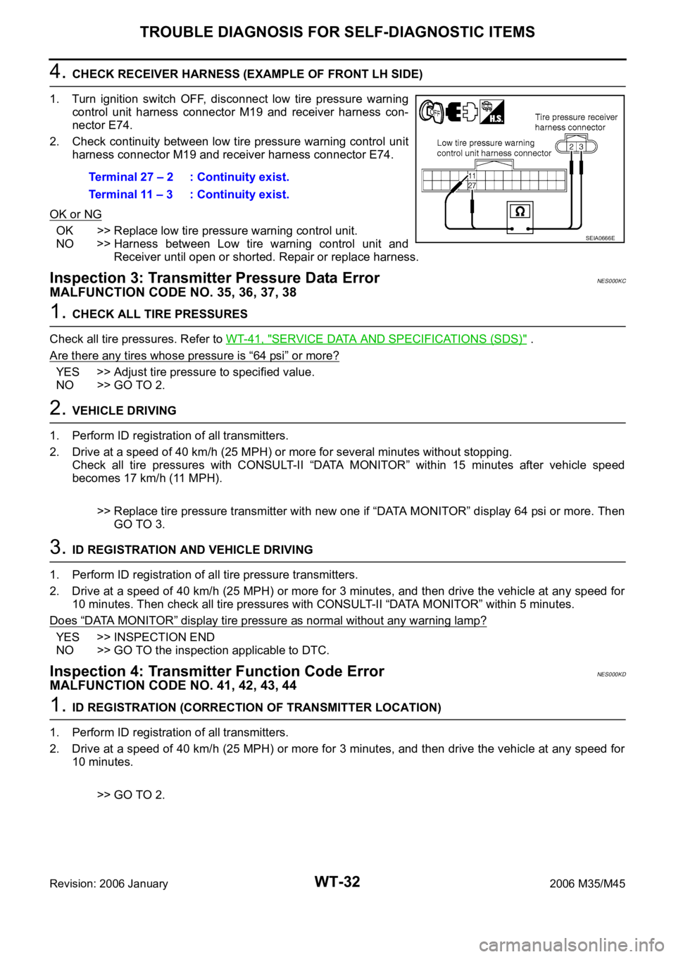
4. CHECK RECEIVER HARNESS (EXAMPLE OF FRONT LH SIDE)
1. Turn ignition switch OFF, disconnect low tire pressure warning
control unit harness connector M19 and receiver harness con-
nector E74.
2. Check continuity between low tire pressure warning control unit
harness connector M19 and receiver harness connector E74.
OK or NG
OK >> Replace low tire pressure warning control unit.
NO >> Harness between Low tire warning control unit and
Receiver until open or shorted. Repair or replace harness.
Inspection 3: Transmitter Pressure Data ErrorNES000KC
MALFUNCTION CODE NO. 35, 36, 37, 38
1. CHECK ALL TIRE PRESSURES
Check all tire pressures. Refer to WT-41, "
SERVICE DATA AND SPECIFICATIONS (SDS)" .
Are there any tires whose pressure is
“64 psi” or more?
YES >> Adjust tire pressure to specified value.
NO >> GO TO 2.
2. VEHICLE DRIVING
1. Perform ID registration of all transmitters.
2. Drive at a speed of 40 km/h (25 MPH) or more for several minutes without stopping.
Check all tire pressures with CONSULT-II “DATA MONITOR” within 15 minutes after vehicle speed
becomes 17 km/h (11 MPH).
>> Replace tire pressure transmitter with new one if “DATA MONITOR” display 64 psi or more. Then
GO TO 3.
3. ID REGISTRATION AND VEHICLE DRIVING
1. Perform ID registration of all tire pressure transmitters.
2. Drive at a speed of 40 km/h (25 MPH) or more for 3 minutes, and then drive the vehicle at any speed for
10 minutes. Then check all tire pressures with CONSULT-II “DATA MONITOR” within 5 minutes.
Does
“DATA MONITOR” display tire pressure as normal without any warning lamp?
YES >> INSPECTION END
NO >> GO TO the inspection applicable to DTC.
Inspection 4: Transmitter Function Code ErrorNES000KD
MALFUNCTION CODE NO. 41, 42, 43, 44
1. ID REGISTRATION (CORRECTION OF TRANSMITTER LOCATION)
1. Perform ID registration of all transmitters.
2. Drive at a speed of 40 km/h (25 MPH) or more for 3 minutes, and then drive the vehicle at any speed for
10 minutes.
>> GO TO 2. Terminal 27 – 2 : Continuity exist.
Terminal 11 – 3 : Continuity exist.
SEIA0666E
Page 5566 of 5621
SERVICE DATA AND SPECIFICATIONS (SDS)
WT-41
C
D
F
G
H
I
J
K
L
MA
B
WT
Revision: 2006 January2006 M35/M45
SERVICE DATA AND SPECIFICATIONS (SDS)PFP:00030
Road WheelNES000KP
TireNES000KQ
Unit: kPa (kg/cm2 , psi) Standard itemAllowable value
Aluminum Steel (for emergency use)
Maximum radial runout limitLateral deflectionLess than 0.3 mm
(0.012 in)Less than 1.5 mm
(0.059 in)
Radial deflectionLess than 0.3 mm
(0.012 in)Less than 1.5 mm
(0.059 in)
Maximum allowable unbalanceDynamic
(At rim flange)Less than 7 g (0.25 oz) (one side)
Static
(At rim flange)Less than 14 g (0.49 oz)
Tire sizeAir pressure
Front Rear
245/40R19 94W 230 (2.3, 33) 230 (2.3, 33)
P245/45R18 96V 230 (2.3, 33) 230 (2.3, 33)
T145/80D17 107M 420 (4.2, 60) 420 (4.2, 60)
Page 5567 of 5621
WT-42
SERVICE DATA AND SPECIFICATIONS (SDS)
Revision: 2006 January2006 M35/M45
Page 5570 of 5621

PRECAUTION
WW-3
C
D
E
F
G
H
I
J
L
MA
B
WW
Revision: 2006 January2006 M35/M45
PRECAUTION PFP:00011
Precautions for Supplemental Restraint System (SRS) “AIR BAG” and “SEAT
BELT PRE-TENSIONER”
NKS003WA
The Supplemental Restraint System such as “AIR BAG” and “SEAT BELT PRE-TENSIONER”, used along
with a front seat belt, helps to reduce the risk or severity of injury to the driver and front passenger for certain
types of collision. This system includes seat belt switch inputs and dual stage front air bag modules. The SRS
system uses the seat belt switches to determine the front air bag deployment, and may only deploy one front
air bag, depending on the severity of a collision and whether the front occupants are belted or unbelted.
Information necessary to service the system safely is included in the SRS and SB section of this Service Man-
ual.
WAR NING :
To avoid rendering the SRS inoperative, which could increase the risk of personal injury or death
in the event of a collision which would result in air bag inflation, all maintenance must be per-
formed by an authorized NISSAN/INFINITI dealer.
Improper maintenance, including incorrect removal and installation of the SRS, can lead to per-
sonal injury caused by unintentional activation of the system. For removal of Spiral Cable and Air
Bag Module, see the SRS section.
Do not use electrical test equipment on any circuit related to the SRS unless instructed to in this
Service Manual. SRS wiring harnesses can be identified by yellow and/or orange harnesses or
harness connectors.