2006 INFINITI M35 service
[x] Cancel search: servicePage 5187 of 5621

SE-6
SQUEAK AND RATTLE TROUBLE DIAGNOSES
Revision: 2006 January2006 M35/M45
DUPLICATE THE NOISE AND TEST DRIVE
If possible, drive the vehicle with the customer until the noise is duplicated. Note any additional information on
the Diagnostic Worksheet regarding the conditions or location of the noise. This information can be used to
duplicate the same conditions when you confirm the repair.
If the noise can be duplicated easily during the test drive, to help identify the source of the noise, try to dupli-
cate the noise with the vehicle stopped by doing one or all of the following:
1) Close a door.
2) Tap or push/pull around the area where the noise appears to be coming from.
3) Rev the engine.
4) Use a floor jack to recreate vehicle “twist”.
5) At idle, apply engine load (electrical load, half-clutch on M/T models, drive position on A/T models).
6) Raise the vehicle on a hoist and hit a tire with a rubber hammer.
Drive the vehicle and attempt to duplicate the conditions the customer states exist when the noise occurs.
If it is difficult to duplicate the noise, drive the vehicle slowly on an undulating or rough road to stress the
vehicle body.
CHECK RELATED SERVICE BULLETINS
After verifying the customer concern or symptom, check ASIST for Technical Service Bulletins (TSBs) related
to that concern or symptom.
If a TSB relates to the symptom, follow the procedure to repair the noise.
LOCATE THE NOISE AND IDENTIFY THE ROOT CAUSE
1. Narrow down the noise to a general area. To help pinpoint the source of the noise, use a listening tool
(Chassis Ear: J-39570, Engine Ear and mechanics stethoscope).
2. Narrow down the noise to a more specific area and identify the cause of the noise by:
removing the components in the area that you suspect the noise is coming from.
Do not use too much force when removing clips and fasteners, otherwise clips and fastener can be broken
or lost during the repair, resulting in the creation of new noise.
tapping or pushing/pulling the component that you suspect is causing the noise.
Do not tap or push/pull the component with excessive force, otherwise the noise will be eliminated only
temporarily.
feeling for a vibration with your hand by touching the component(s) that you suspect is (are) causing the
noise.
placing a piece of paper between components that you suspect are causing the noise.
looking for loose components and contact marks.
Refer to SE-7, "
Generic Squeak and Rattle Troubleshooting" .
REPAIR THE CAUSE
If the cause is a loose component, tighten the component securely.
If the cause is insufficient clearance between components:
–separate components by repositioning or loosening and retightening the component, if possible.
–insulate components with a suitable insulator such as urethane pads, foam blocks, felt cloth tape or ure-
thane tape. A Nissan Squeak and Rattle Kit (J-43980) is available through your authorized Nissan Parts
Department.
CAUTION:
Do not use excessive force as many components are constructed of plastic and may be damaged.
NOTE:
Always check with the Parts Department for the latest parts information.
The following materials are contained in the Nissan Squeak and Rattle Kit (J-43980). Each item can be
ordered separately as needed.
URETHANE PADS [1.5 mm (0.059 in) thick]
Insulates connectors, harness, etc.
76268-9E005: 100
135 mm (3.945.31 in)/76884-71L01: 6085 mm (2.363.35 in)/76884-
71L02: 15
25 mm (0.590.98 in)
INSULATOR (Foam blocks)
Insulates components from contact. Can be used to fill space behind a panel.
73982-9E000: 45 mm (1.77 in) thick, 50
50 mm (1.971.97 in)/73982-50Y00:
10 mm (0.39 in) thick, 50
50 mm (1.971.97 in)
Page 5220 of 5621

AUTOMATIC DRIVE POSITIONER
SE-39
C
D
E
F
G
H
J
K
L
MA
B
SE
Revision: 2006 January2006 M35/M45
Work Flow NIS00261
1. Check the symptom and customer's requests.
2. Understand the system description. Refer to SE-12, "
System Description" .
3. Perform the self-diagnosis results, using CONSULT-II. Refer to SE-35, "
CONSULT-II Function (AUTO
DRIVE POS.)" .
4. Repair or replace depending on the self-diagnostic results.
5. Based on the trouble diagnosis chart, repair or replace the cause of the malfunction. Refer to SE-39,
"Symptom Chart" .
6. Does the automatic drive positioned system operate normally?
If it is normal, GO TO 8.
If it is not normal, GO TO 3.
7. INSPECTION END
Symptom ChartNIS00262
NOTE:
Always check the “Work flow” before performing diagnosis in the following table, Refer to SE-39, "
Work Flow"
.
Symptom Diagnoses / service procedureReference
page
All of automatic operation dose not operate.1. BCM power supply and ground circuit check.SE-41
2. Driver seat control unit power supply and ground cir-
cuit check.SE-42
3. Automatic drive positioner control unit power supply
and ground circuit check.SE-43
Sliding function does not operate (automatically and man-
ually).Sliding motor circuit check SE-44
Reclining function does not operate (automatically and
manually).Reclining motor circuit check SE-45
Front lifting function does not operate (automatically and
manually).Front lifting motor circuit checkSE-46
Rear lifting function not operate (automatically and manu-
ally).Rear lifting motor circuit checkSE-48
Tilt function does not operate (automatically and manu-
ally).Tilt motor circuit checkSE-50
Telescopic function does not operate (automatically and
manually).Telescopic motor circuit checkSE-49
Sliding function does not operate automatically. Sliding sensor circuit checkSE-52
Reclining function does not operate automatically. Reclining sensor circuit checkSE-54
Front lifting function does not operate automatically. Front lifting sensor circuit checkSE-56
Rear lifting function does not operate automatically. Rear lifting sensor circuit checkSE-58
Tilt function does not operate automatically. Tilt sensor circuit checkSE-62
Telescopic function does not operate automatically. Telescopic sensor circuit checkSE-60
Sliding function does not operate manually. Sliding switch circuit checkSE-68
Reclining function does not operate manually. Reclining switch circuit checkSE-70
Front lifting function does not operate manually. Lifting switch (front) circuit checkSE-72
Rear lifting function does not operate manually. Lifting switch (rear) circuit checkSE-74
Tilt function does not operate manually. Tilt switch circuit checkSE-78
Telescopic function does not operate manually. Telescopic switch circuit checkSE-76
All of seat operation dose not operate manually. Power seat switch ground circuit check.SE-75
Page 5221 of 5621

SE-40
AUTOMATIC DRIVE POSITIONER
Revision: 2006 January2006 M35/M45
Only seat memory and set switch operation does not
operate.1. Perform storing memorySE-13
2. Seat memory and set switch circuit checkSE-80
Seat memory indicator lamps 1 and 2 do not illuminate. Seat memory indicator lamp circuit checkSE-81
Entry/Exiting operation does not operated.1. Check system setting.SE-162. Perform initialization.SE-16
3. Front door switch (driver side) circuit checkSE-86
LH or RH door mirror face does not produce the stored
angle, during the memory operation.1. Door mirror sensor power supply and ground circuit
checkSE-832. Door mirror sensor LH circuit checkSE-63
3. Door mirror sensor RH circuit checkSE-66
4. Replace automatic drive positioner control unitSE-11
Intelligent key interlock operation does not operate.
(Other automatic operation and Intelligent Key system are
normal)Perform storing memorySE-13
Lumber support does not operate Lumber support circuit checkSE-89
Symptom Diagnoses / service procedureReference
page
Page 5284 of 5621

SE-103
C
D
E
F
G
H
J
K
L
MA
B
SE
Revision: 2006 January2006 M35/M45
Work FlowNIS00277
1. Check the symptom and customer's requests.
2. Understand the outline of system. Refer to S")
POWER SEAT(REAR)
SE-103
C
D
E
F
G
H
J
K
L
MA
B
SE
Revision: 2006 January2006 M35/M45
Work FlowNIS00277
1. Check the symptom and customer's requests.
2. Understand the outline of system. Refer to SE-95, "
System Description" .
3. According to the trouble diagnosis chart, repair or replace the cause of the malfunction. Refer to SE-103,
"Trouble Diagnoses Symptom Chart" .
4. Does rear power seat operate normally? YES: GO TO 5, NO: GO TO 4.
5. INSPECTION END.
Trouble Diagnoses Symptom ChartNIS00278
Check that other systems using the signal of the following systems operate normally.
Rear Power Seat Power Supply Circuit InspectionNIS00279
1. CHECK FUSIBLE LINK
Check 50A fusible link (letter F located in the fuse and fusible link box).
NOTE:
Refer to SE-95, "
Component Parts and Harness Connector Location" .
OK or NG
OK >> GO TO 2.
NG >> If fuse is blown, be sure to eliminate cause of malfunction before installing new fuse, refer to PG-
3, "POWER SUPPLY ROUTING CIRCUIT" .
2. CHECK CIRCUIT BREAKER
Check circuit breaker.
NOTE:
Refer to PG-3, "
POWER SUPPLY ROUTING CIRCUIT" .
OK or NG
OK >> Check the condition of the harness and connector.
NG >> Replace the circuit breaker.
Symptom Diagnoses / service procedure Refer to page
Rear power seat LH, RH do not operate. Rear power seat power supply circuit inspectionSE-103
Rear power seat LH or RH sliding switch does not operate
moreover, retreat function does not operate if the door is
opened1. Rear seat control unit power supply and
ground circuit inspectionSE-104
2. Rear seat sliding motor circuit inspectionSE-105
Rear power seat LH or RH does not operate, but retreat func-
tion operates when the door is openedRear power seat switch circuit inspectionSE-106
Rear power seat LH and RH retreat function does not operate,
but operates by sliding switchAutomatic return cancel switch inspectionSE-109
Rear power seat LH or RH retreat function does not operate,
but operates by a sliding switch1. Rear door switch circuit inspectionSE-1102. Automatic return cancel switch circuit inspec-
tionSE-108
3. Rear seat sliding sensor circuit inspectionSE-111
Page 5306 of 5621

CLIMATE CONTROLLED SEAT
SE-125
C
D
E
F
G
H
J
K
L
MA
B
SE
Revision: 2006 January2006 M35/M45
Trouble Diagnoses Symptom ChartNIS0027O
NOTE:
Make sure other systems using the signal of the following systems operate normally.
NOTE:
The climate controlled seat blower keep low speed for approximately 60 seconds turning the switch.
The climate controlled seat system is downed when the temperature sensor set as the seat cushion and
the seatback's thermal electric device machine detects 20
C (68F) or more of mutual differences of tem-
perature.
Symptom Diagnoses / service procedureRefer to
page
Climate controlled seat do not operate (Neither the driver's
side nor passenger's side operate).1. Climate controlled seat control unit power supply cir-
cuit check.SE-126
All the driver side or passenger side climate controlled
seat do not operate.1. Climate controlled seat control unit power supply and
ground circuit inspection.SE-1272. Climate controlled seat switch power supply circuit
inspectionSE-130
3. Climate controlled seat blower motor circuit inspection.SE-140
4. Replace climate controlled seat control unit.SE-113
Climate controlled seat blower motor speed cannot adjust.1. Climate controlled seat switch power supply circuit
inspectionSE-1302. Climate controlled seat switch circuit inspectionSE-131
3. Climate controlled seat control unit inspection.SE-142
4. Replace climate controlled seat blower motor.SE-113
The climate controlled seat dose not operates when the
switch is done in HEAT or COOL.Climate controlled seat switch circuit inspection.SE-131
When the climate controlled seat switch is turned on,
operation stops at nose (When the climate controlled seat
switch is in HEAT or COOL mode after ignition switch is
turned ON again, the motor operates).1. Seat cushion thermal electric device sensor circuit
inspection.SE-1372. Seat cushion thermal electric device circuit inspectionSE-135
3. Seatback thermal electric device sensor circuit inspec-
tion.SE-139
4. Seatback thermal electric device circuit inspectionSE-136
5. Climate controlled seat blower motor circuit inspection.SE-140
6. Replace Climate controlled seat control unitSE-113
The climate controlled seat switch indicator do not oper-
ated with HEAT or COOL positionClimate controlled seat switch indicator circuit inspectionSE-133
Page 5332 of 5621
HEATED SEAT
SE-151
C
D
E
F
G
H
J
K
L
MA
B
SE
Revision: 2006 January2006 M35/M45
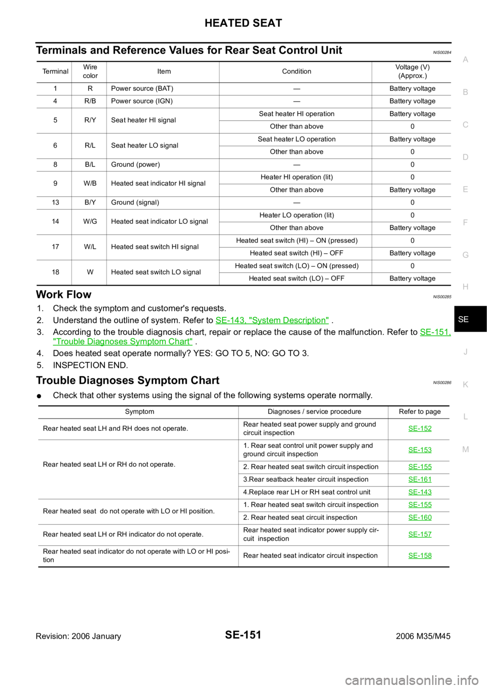
Terminals and Reference Values for Rear Seat Control UnitNIS00284
Work FlowNIS00285
1. Check the symptom and customer's requests.
2. Understand the outline of system. Refer to SE-143, "
System Description" .
3. According to the trouble diagnosis chart, repair or replace the cause of the malfunction. Refer to SE-151,
"Trouble Diagnoses Symptom Chart" .
4. Does heated seat operate normally? YES: GO TO 5, NO: GO TO 3.
5. INSPECTION END.
Trouble Diagnoses Symptom ChartNIS00286
Check that other systems using the signal of the following systems operate normally.
Te r m i n a lWire
colorItem ConditionVoltage (V)
(Approx.)
1 R Power source (BAT) — Battery voltage
4 R/B Power source (IGN) — Battery voltage
5 R/Y Seat heater HI signalSeat heater HI operation Battery voltage
Other than above 0
6 R/L Seat heater LO signalSeat heater LO operation Battery voltage
Other than above 0
8 B/L Ground (power) — 0
9 W/B Heated seat indicator HI signalHeater HI operation (lit) 0
Other than above Battery voltage
13 B/Y Ground (signal) — 0
14 W/G Heated seat indicator LO signalHeater LO operation (lit) 0
Other than above Battery voltage
17 W/L Heated seat switch HI signalHeated seat switch (HI) – ON (pressed) 0
Heated seat switch (HI) – OFF Battery voltage
18 W Heated seat switch LO signalHeated seat switch (LO) – ON (pressed) 0
Heated seat switch (LO) – OFF Battery voltage
Symptom Diagnoses / service procedure Refer to page
Rear heated seat LH and RH does not operate.Rear heated seat power supply and ground
circuit inspectionSE-152
Rear heated seat LH or RH do not operate.1. Rear seat control unit power supply and
ground circuit inspectionSE-1532. Rear heated seat switch circuit inspectionSE-155
3.Rear seatback heater circuit inspectionSE-161
4.Replace rear LH or RH seat control unitSE-143
Rear heated seat do not operate with LO or HI position.1. Rear heated seat switch circuit inspectionSE-1552. Rear heated seat circuit inspectionSE-160
Rear heated seat LH or RH indicator do not operate.Rear heated seat indicator power supply cir-
cuit inspectionSE-157
Rear heated seat indicator do not operate with LO or HI posi-
tionRear heated seat indicator circuit inspectionSE-158
Page 5362 of 5621

H RESTRAINTS
CONTENTS
C
D
E
F
G
I
J
K
L
M
SECTION SRS
A
B
SRS
Revision: 2006 January2006 M35/M45
SUPPLEMENTAL RESTRAINT SYSTEM (SRS)
PRECAUTIONS ...........")
SRS-1
SUPPLEMENTAL RESTRAINT SYSTEM (SRS)
H RESTRAINTS
CONTENTS
C
D
E
F
G
I
J
K
L
M
SECTION SRS
A
B
SRS
Revision: 2006 January2006 M35/M45
SUPPLEMENTAL RESTRAINT SYSTEM (SRS)
PRECAUTIONS .......................................................... 3
Precautions for Supplemental Restraint System
(SRS) “AIR BAG” and “SEAT BELT PRE-TEN-
SIONER” .................................................................. 3
Precautions for SRS “AIR BAG” and “SEAT BELT
PRE-TENSIONER” Service ..................................... 3
Occupant Classification System Precaution ............ 3
PREPARATION ........................................................... 4
Commercial Service Tools ........................................ 4
SUPPLEMENTAL RESTRAINT SYSTEM (SRS) ....... 5
SRS Configuration ..............................................
..... 5
Front Seat Belt Pre-Tensioner with Load Limiter ...... 6
Front Side Air Bag .................................................... 6
Side Curtain Air Bag ................................................. 6
Occupant Classification System (OCS) ................... 7
Passenger Air Bag Status Condition ........................ 7
Component Parts of Occupant Classification Sys-
tem ........................................................................... 7
TROUBLE DIAGNOSIS .............................................. 8
Trouble Diagnosis Introduction ................................. 8
DIAGNOSIS FUNCTION ....................................... 8
HOW TO PERFORM TROUBLE DIAGNOSIS
FOR QUICK AND ACCURATE REPAIR ............... 8
WORK FLOW ........................................................ 9
Component Parts Location ..................................... 10
Schematic ............................................................... 11
Wiring Diagram — SRS — ..................................... 12
CONSULT-II Function ............................................ 17
DIAGNOSIS MODE FOR CONSULT-II ............... 17
HOW TO CHANGE SELF-DIAGNOSIS MODE
WITH CONSULT-II .............................................. 17
HOW TO ERASE SELF-DIAGNOSTIC
RESULTS ............................................................ 18
Self-Diagnosis Function (Without CONSULT-II) ..... 18
HOW TO CHANGE SELF-DIAGNOSIS MODE
WITHOUT CONSULT-II ...................................... 18
HOW TO ERASE SELF-DIAGNOSTIC
RESULTS ............................................................ 18
SRS Operation Check ............................................ 19
DIAGNOSTIC PROCEDURE 1 ........................... 19Trouble Diagnosis with CONSULT-II ...................... 21
DIAGNOSTIC PROCEDURE 2 ........................... 21
DIAGNOSTIC PROCEDURE 3 ........................... 25
DIAGNOSTIC PROCEDURE 4 (CONTINUED
FROM DIAGNOSTIC PROCEDURE 2) .............. 27
DIAGNOSTIC PROCEDURE 5 ........................... 27
Trouble Diagnosis without CONSULT-II ................. 32
DIAGNOSTIC PROCEDURE 6 ........................... 32
WARNING LAMP FLASH CODE CHART ........... 32
Trouble Diagnosis: “AIR BAG” Warning Lamp Does
Not Turn OFF ......................................................... 36
DIAGNOSTIC PROCEDURE 7 ........................... 36
Trouble Diagnosis: “AIR BAG” Warning Lamp Does
Not Turn ON ........................................................... 37
DIAGNOSTIC PROCEDURE 8 ........................... 37
DRIVER AIR BAG MODULE .................................... 38
Removal and Installation ........................................ 38
REMOVAL ........................................................
... 38
INSTALLATION ................................................... 39
SPIRAL CABLE ........................................................ 40
Removal and Installation ........................................ 40
REMOVAL ........................................................
... 40
INSTALLATION ................................................... 40
FRONT PASSENGER AIR BAG MODULE .............. 42
Removal and Installation ........................................ 42
REMOVAL ........................................................
... 42
INSTALLATION ................................................... 42
SIDE CURTAIN AIR BAG MODULE ........................ 43
Removal and Installation ........................................ 43
REMOVAL ........................................................
... 43
INSTALLATION ................................................... 44
CRASH ZONE SENSOR ........................................... 45
Removal and Installation ........................................ 45
REMOVAL ........................................................
... 45
INSTALLATION ................................................... 45
SIDE AIR BAG (SATELLITE) SENSOR ................... 46
Removal and Installation ........................................ 46
REMOVAL ........................................................
... 46
INSTALLATION ................................................... 46
Page 5364 of 5621
 “AIR BAG” and “SEAT
BELT PRE-TENSIONER�")
PRECAUTIONS
SRS-3
C
D
E
F
G
I
J
K
L
MA
B
SRS
Revision: 2006 January2006 M35/M45
PRECAUTIONSPFP:00001
Precautions for Supplemental Restraint System (SRS) “AIR BAG” and “SEAT
BELT PRE-TENSIONER”
NHS0008O
The Supplemental Restraint System such as “AIR BAG” and “SEAT BELT PRE-TENSIONER”, used along
with a front seat belt, helps to reduce the risk or severity of injury to the driver and front passenger for certain
types of collision. This system includes seat belt switch inputs and dual stage front air bag modules. The SRS
system uses the seat belt switches to determine the front air bag deployment, and may only deploy one front
air bag, depending on the severity of a collision and whether the front occupants are belted or unbelted.
Information necessary to service the system safely is included in the SRS and SB section of this Service Man-
ual.
WAR NING :
To avoid rendering the SRS inoperative, which could increase the risk of personal injury or death
in the event of a collision which would result in air bag inflation, all maintenance must be per-
formed by an authorized NISSAN/INFINITI dealer.
Improper maintenance, including incorrect removal and installation of the SRS, can lead to per-
sonal injury caused by unintentional activation of the system. For removal of Spiral Cable and Air
Bag Module, see the SRS section.
Do not use electrical test equipment on any circuit related to the SRS unless instructed to in this
Service Manual. SRS wiring harnesses can be identified by yellow and/or orange harnesses or
harness connectors.
Precautions for SRS “AIR BAG” and “SEAT BELT PRE-TENSIONER” ServiceNHS0008P
Do not use electrical test equipment to check SRS circuits unless instructed to in this Service Manual.
Before servicing the SRS, turn ignition switch OFF, disconnect both battery cables and wait at least 3 min-
utes.
For approximately 3 minutes after the cables are removed, it is still possible for the air bag and seat belt
pre-tensioner to deploy. Therefore, do not work on any SRS connectors or wires until at least 3 minutes
have passed.
Diagnosis sensor unit must always be installed with their arrow marks “” pointing towards the front of the
vehicle for proper operation. Also check diagnosis sensor unit for cracks, deformities or rust before instal-
lation and replace as required.
The spiral cable must be aligned with the neutral position since its rotations are limited. Do not turn steer-
ing wheel and column after removal of steering gear.
Handle air bag module carefully. Always place driver and front passenger air bag modules with the pad
side facing upward and seat mounted front side air bag module standing with the stud bolt side facing
down.
Conduct self-diagnosis to check entire SRS for proper function after replacing any components.
After air bag inflates, the front instrument panel assembly should be replaced if damaged.
Always replace instrument panel pad following front passenger air bag deployment.
Occupant Classification System PrecautionNHS0008Q
Replace occupant classification system control unit and passenger front seat cushion as an assembly.
Refer to SE-165, "
Passenger's Seat Components" .