2006 INFINITI M35 ignition
[x] Cancel search: ignitionPage 1694 of 5621
![INFINITI M35 2006 Factory Service Manual TROUBLE DIAGNOSIS
EC-151
[VQ35DE]
C
D
E
F
G
H
I
J
K
L
MA
EC
Revision: 2006 January2006 M35/M45
HO2S2 HTR (B1)
HO2S2 HTR (B2)
Engine speed: Below 3,600 rpm after the following conditions are met.
–En](/manual-img/42/57023/w960_57023-1693.png "INFINITI M35 2006 Factory Service Manual TROUBLE DIAGNOSIS
EC-151
[VQ35DE]
C
D
E
F
G
H
I
J
K
L
MA
EC
Revision: 2006 January2006 M35/M45
HO2S2 HTR (B1)
HO2S2 HTR (B2)
Engine speed: Below 3,600 rpm after the following conditions are met.
–En")
TROUBLE DIAGNOSIS
EC-151
[VQ35DE]
C
D
E
F
G
H
I
J
K
L
MA
EC
Revision: 2006 January2006 M35/M45
HO2S2 HTR (B1)
HO2S2 HTR (B2)
Engine speed: Below 3,600 rpm after the following conditions are met.
–Engine: After warming up
–Keeping the engine speed between 3,500 and 4,000 rpm for 1 minute and at
idle for 1 minute under no loadON
Engine speed: Above 3,600 rpm OFF
I/P PULLY SPD
Vehicle speed: More than 20 km/h (12 MPH)Almost the same speed as
the tachometer indication
VEHICLE SPEED
Turn drive wheels and compare CONSULT-II value with the speedometer
indication.Almost the same speed as
the speedometer indication
TRVL AFTER MIL
Ignition switch: ONVehicle has traveled after MIL has turned
ON.0 - 65,535 km
(0 - 40,723 miles)
A/F S1 HTR (B1)
A/F S1 HTR (B2)
Engine: After warming up, idle the engine 0 - 100%
AC PRESS SEN
Engine: Idle
Both A/C switch and blower fan switch: ON (Compressor operates)1.0 - 4.0V
VHCL SPEED SE
Turn drive wheels and compare CONSULT-II value with the speedometer
indication.Almost the same speed as
the speedometer indication
SET VHCL SPD
Engine: Running ASCD: OperatingThe preset vehicle speed is
displayed
MAIN SW
Ignition switch: ONMAIN switch: Pressed ON
MAIN switch: Released OFF
CANCEL SW
Ignition switch: ONCANCEL switch: Pressed ON
CANCEL switch: Released OFF
RESUME/ACC SW
Ignition switch: ONRESUME/ACCELERATE switch:
PressedON
RESUME/ACCELERATE switch:
ReleasedOFF
SET SW
Ignition switch: ONSET/COAST switch: Pressed ON
SET/COAST switch: Released OFF
BRAKE SW1
(ICC/ASCD brake
switch)
Ignition switch: ONBrake pedal: Fully released ON
Brake pedal: Slightly depressed OFF
BRAKE SW2
(Stop lamp switch)
Ignition switch: ONBrake pedal: Fully released OFF
Brake pedal: Slightly depressed ON
DIST SW
Ignition switch: ONDISTANCE switch: Pressed ON
DISTANCE switch: Released OFF
CRUISE LAMP
Ignition switch: ONMAIN switch: Pressed at the 1st time
at the 2nd timeON OFF
SET LAMP
MAIN switch: ON
When vehicle speed is between
40 km/h (25 MPH) and 144 km/h
(89 MPH)ASCD: Operating ON
ASCD: Not operating OFF
FA N D U T Y
Engine: Running 0 - 100%
AC EVA TEMP
Engine: Idle
Both A/C switch and blower fan switch: ON (Compressor operates)
AC EVA TARGET
Engine: Idle
Both A/C switch and blower fan switch: ON (Compressor operates)
ALT DUTY
Engine: Idle 0 - 80% MONITOR ITEM CONDITION SPECIFICATION
Page 1696 of 5621
![INFINITI M35 2006 Factory Service Manual TROUBLE DIAGNOSIS
EC-153
[VQ35DE]
C
D
E
F
G
H
I
J
K
L
MA
EC
Revision: 2006 January2006 M35/M45
Major Sensor Reference Graph in Data Monitor ModeNBS004TA
The following are the major sensor reference gr](/manual-img/42/57023/w960_57023-1695.png "INFINITI M35 2006 Factory Service Manual TROUBLE DIAGNOSIS
EC-153
[VQ35DE]
C
D
E
F
G
H
I
J
K
L
MA
EC
Revision: 2006 January2006 M35/M45
Major Sensor Reference Graph in Data Monitor ModeNBS004TA
The following are the major sensor reference gr")
TROUBLE DIAGNOSIS
EC-153
[VQ35DE]
C
D
E
F
G
H
I
J
K
L
MA
EC
Revision: 2006 January2006 M35/M45
Major Sensor Reference Graph in Data Monitor ModeNBS004TA
The following are the major sensor reference graphs in “DATA MONITOR” mode.
CLSD THL POS, ACCEL SEN 1, THRTL SEN 1
Below is the data for “CLSD THL POS”, “ACCEL SEN 1” and “THRTL SEN 1” when depressing the accelera-
tor pedal with the ignition switch ON and with selector lever in D position.
The signal of “ACCEL SEN 1” and “THRTL SEN 1” should rise gradually without any intermittent drop or rise
after “CLSD THL POS” is changed from “ON” to “OFF”.
ENG SPEED, MAS A/F SE-B1, THRTL SEN 1, HO2S2 (B1), INJ PULSE-B1
Below is the data for “ENG SPEED”, “MAS A/F SE-B1”, “THRTL SEN 1”, “HO2S2 (B1)” and “INJ PULSE-B1”
when revving engine quickly up to 4,800 rpm under no load after warming up engine sufficiently.
Each value is for reference, the exact value may vary.
PBIB0198E
PBIB2445E
Page 1703 of 5621
EC-160
[VQ35DE]
TROUBLE DIAGNOSIS - SPECIFICATION VALUE
Revision: 2006 January2006 M35/M45
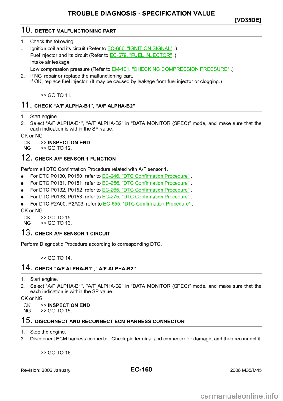
10. DETECT MALFUNCTIONING PART
1. Check the following.
–Ignition coil and its circuit (Refer to EC-666, "IGNITION SIGNAL" .)
–Fuel injector and its circuit (Refer to EC-679, "FUEL INJECTOR" .)
–Intake air leakage
–Low compression pressure (Refer to EM-101, "CHECKING COMPRESSION PRESSURE" .)
2. If NG, repair or replace the malfunctioning part.
If OK, replace fuel injector. (It may be caused by leakage from fuel injector or clogging.)
>> GO TO 11.
11 . CHECK “A/F ALPHA-B1”, “A/F ALPHA-B2”
1. Start engine.
2. Select “A/F ALPHA-B1”, “A/F ALPHA-B2” in “DATA MONITOR (SPEC)” mode, and make sure that the
each indication is within the SP value.
OK or NG
OK >>INSPECTION END
NG >> GO TO 12.
12. CHECK A/F SENSOR 1 FUNCTION
Perform all DTC Confirmation Procedure related with A/F sensor 1.
For DTC P0130, P0150, refer to EC-246, "DTC Confirmation Procedure" .
For DTC P0131, P0151, refer to EC-256, "DTC Confirmation Procedure" .
For DTC P0132, P0152, refer to EC-265, "DTC Confirmation Procedure" .
For DTC P0133, P0153, refer to EC-275, "DTC Confirmation Procedure" .
For DTC P2A00, P2A03, refer to EC-655, "DTC Confirmation Procedure" .
OK or NG
OK >> GO TO 15.
NG >> GO TO 13.
13. CHECK A/F SENSOR 1 CIRCUIT
Perform Diagnostic Procedure according to corresponding DTC.
>> GO TO 14.
14. CHECK “A/F ALPHA-B1”, “A/F ALPHA-B2”
1. Start engine.
2. Select “A/F ALPHA-B1”, “A/F ALPHA-B2” in “DATA MONITOR (SPEC)” mode, and make sure that the
each indication is within the SP value.
OK or NG
OK >>INSPECTION END
NG >> GO TO 15.
15. DISCONNECT AND RECONNECT ECM HARNESS CONNECTOR
1. Stop the engine.
2. Disconnect ECM harness connector. Check pin terminal and connector for damage, and then reconnect it.
>> GO TO 16.
Page 1705 of 5621
![INFINITI M35 2006 Factory Service Manual EC-162
[VQ35DE]
TROUBLE DIAGNOSIS - SPECIFICATION VALUE
Revision: 2006 January2006 M35/M45
20. CHECK “A/F ALPHA-B1”, “A/F ALPHA-B2”, AND “B/FUEL SCHDL”
Select “A/F ALPHA-B1”, “A/F](/manual-img/42/57023/w960_57023-1704.png "INFINITI M35 2006 Factory Service Manual EC-162
[VQ35DE]
TROUBLE DIAGNOSIS - SPECIFICATION VALUE
Revision: 2006 January2006 M35/M45
20. CHECK “A/F ALPHA-B1”, “A/F ALPHA-B2”, AND “B/FUEL SCHDL”
Select “A/F ALPHA-B1”, “A/F")
EC-162
[VQ35DE]
TROUBLE DIAGNOSIS - SPECIFICATION VALUE
Revision: 2006 January2006 M35/M45
20. CHECK “A/F ALPHA-B1”, “A/F ALPHA-B2”, AND “B/FUEL SCHDL”
Select “A/F ALPHA-B1”, “A/F ALPHA-B2”, and “B/FUEL SCHDL” in “DATA MONITOR (SPEC)” mode, and
make sure that the each indication is within the SP value.
OK or NG
OK >>INSPECTION END
NG (“B/FUEL SCHDL” is more, “A/F ALPHA-B1”, “A/F ALPHA-B2” are less than the SP value)>>GO TO 21.
21. DISCONNECT AND RECONNECT MASS AIR FLOW SENSOR HARNESS CONNECTOR
1. Stop the engine.
2. Disconnect mass air flow sensor harness connector. Check pin terminal and connector for damage and
then reconnect it again.
>> GO TO 22.
22. CHECK “A/F ALPHA-B1”, “A/F ALPHA-B2”
1. Start engine.
2. Select “A/F ALPHA-B1”, “A/F ALPHA-B2” in “DATA MONITOR (SPEC)” mode, and make sure that the
each indication is within the SP value.
OK or NG
OK >> 1. Detect malfunctioning part of mass air flow sensor circuit and repair it. Refer to EC-214, "DTC
P0102, P0103 MAF SENSOR" .
2. GO TO 29.
NG >> GO TO 23.
23. CHECK “MAS A/F SE-B1”
Select “MAS A/F SE-B1” in “DATA MONITOR (SPEC)” mode, and
make sure that the indication is within the SP value.
OK or NG
OK >> GO TO 24.
NG (More than the SP value)>>Replace mass air flow sensor, and
then GO TO 29.
24. REPLACE ECM
1. Replace ECM.
2. Perform initialization of IVIS(NATS) system and registration of all IVIS(NATS) ignition key IDs. Refer to
BL-252, "
ECM Re-Communicating Function" .
3. Perform EC-95, "
VIN Registration" .
4. Perform EC-95, "
Accelerator Pedal Released Position Learning" .
5. Perform EC-95, "
Throttle Valve Closed Position Learning" .
6. Perform EC-96, "
Idle Air Volume Learning" .
>> GO TO 29.
PBIB2370E
Page 1710 of 5621
![INFINITI M35 2006 Factory Service Manual POWER SUPPLY AND GROUND CIRCUIT
EC-167
[VQ35DE]
C
D
E
F
G
H
I
J
K
L
MA
EC
Revision: 2006 January2006 M35/M45
Specification data are reference values and are measured between each terminal and ground.](/manual-img/42/57023/w960_57023-1709.png "INFINITI M35 2006 Factory Service Manual POWER SUPPLY AND GROUND CIRCUIT
EC-167
[VQ35DE]
C
D
E
F
G
H
I
J
K
L
MA
EC
Revision: 2006 January2006 M35/M45
Specification data are reference values and are measured between each terminal and ground.")
POWER SUPPLY AND GROUND CIRCUIT
EC-167
[VQ35DE]
C
D
E
F
G
H
I
J
K
L
MA
EC
Revision: 2006 January2006 M35/M45
Specification data are reference values and are measured between each terminal and ground.
CAUTION:
Do not use ECM ground terminals when measuring input/output voltage. Doing so may result in dam-
age to the ECM's transistor. Use a ground other than ECM terminals, such as the ground.
Diagnostic ProcedureNBS004TI
1. INSPECTION START
Start engine.
Is engine running?
Ye s o r N o
Ye s > > G O T O 8 .
No >> GO TO 2.
2. CHECK ECM POWER SUPPLY CIRCUIT-I
1. Turn ignition switch OFF and then ON.
2. Check voltage between ECM terminal 109 and ground with
CONSULT-II or tester.
OK or NG
OK >> GO TO 4.
NG >> GO TO 3.
3. DETECT MALFUNCTIONING PART
Check the following.
Fuse block (J/B) connector M4
15A fuse
Harness for open or short between ECM and fuse
>> Repair open circuit or short to ground or short to power in harness or connectors.
TER-
MINAL
NO.WIRE
COLORITEM CONDITION DATA (DC Voltage)
1 B ECM ground[Engine is running]
Idle speedBody ground
109 L Ignition switch[Ignition switch: OFF]0V
[Ignition switch: ON]BATTERY VOLTAGE
(11 - 14V)
111 S BECM relay
(Self shut-off)[Engine is running]
[Ignition switch: OFF]
A few seconds after turning ignition switch
OFF0 - 1.5V
[Ignition switch: OFF]
More than a few seconds after turning igni-
tion switch OFFBATTERY VOLTAGE
(11 - 14V)
11 5
11 6B
BECM ground[Engine is running]
Idle speedBody ground
11 9
120R
RPower supply for ECM[Ignition switch: ON]BATTERY VOLTAGE
(11 - 14V)
Voltage: Battery voltage
MBIB0015E
Page 1711 of 5621
![INFINITI M35 2006 Factory Service Manual EC-168
[VQ35DE]
POWER SUPPLY AND GROUND CIRCUIT
Revision: 2006 January2006 M35/M45
4. CHECK GROUND CONNECTIONS-I
1. Turn ignition switch OFF.
2. Loosen and retighten two ground screws on the body.
Ref](/manual-img/42/57023/w960_57023-1710.png "INFINITI M35 2006 Factory Service Manual EC-168
[VQ35DE]
POWER SUPPLY AND GROUND CIRCUIT
Revision: 2006 January2006 M35/M45
4. CHECK GROUND CONNECTIONS-I
1. Turn ignition switch OFF.
2. Loosen and retighten two ground screws on the body.
Ref")
EC-168
[VQ35DE]
POWER SUPPLY AND GROUND CIRCUIT
Revision: 2006 January2006 M35/M45
4. CHECK GROUND CONNECTIONS-I
1. Turn ignition switch OFF.
2. Loosen and retighten two ground screws on the body.
Refer to EC-172, "
Ground Inspection" .
OK or NG
OK >> GO TO 5.
NG >> Repair or replace ground connections.
5. CHECK ECM GROUND CIRCUIT FOR OPEN AND SHORT-I
1. Disconnect ECM harness connector.
2. Check harness continuity between ECM terminals 1, 115, 116 and ground.
Refer to Wiring Diagram.
3. Also check harness for short to power.
OK or NG
OK >> GO TO 7.
NG >> GO TO 6.
6. DETECT MALFUNCTIONING PART
Check the following.
Harness connectors F102, M72
Harness for open or short between ECM and ground
>> Repair open circuit or short to power in harness or connectors.
7. CHECK ECM POWER SUPPLY CIRCUIT-II
1. Reconnect ECM harness connector.
2. Turn ignition switch ON.
3. Check voltage between IPDM E/R terminal 17 and ground with
CONSULT-II or tester.
OK or NG
OK >> Go to EC-666, "IGNITION SIGNAL" .
NG >> GO TO 8.
1. Body ground M70 2. Body ground M16
PBIB2782E
Continuity should exist.
Voltage: Battery voltage
PBIB1514E
Page 1712 of 5621
![INFINITI M35 2006 Factory Service Manual POWER SUPPLY AND GROUND CIRCUIT
EC-169
[VQ35DE]
C
D
E
F
G
H
I
J
K
L
MA
EC
Revision: 2006 January2006 M35/M45
8. CHECK ECM POWER SUPPLY CIRCUIT-III
1. Turn ignition switch OFF and wait at least 10 seco](/manual-img/42/57023/w960_57023-1711.png "INFINITI M35 2006 Factory Service Manual POWER SUPPLY AND GROUND CIRCUIT
EC-169
[VQ35DE]
C
D
E
F
G
H
I
J
K
L
MA
EC
Revision: 2006 January2006 M35/M45
8. CHECK ECM POWER SUPPLY CIRCUIT-III
1. Turn ignition switch OFF and wait at least 10 seco")
POWER SUPPLY AND GROUND CIRCUIT
EC-169
[VQ35DE]
C
D
E
F
G
H
I
J
K
L
MA
EC
Revision: 2006 January2006 M35/M45
8. CHECK ECM POWER SUPPLY CIRCUIT-III
1. Turn ignition switch OFF and wait at least 10 seconds.
2. Check voltage between ECM terminals 119, 120 and ground
with CONSULT-II or tester.
OK or NG
OK >> GO TO 15.
NG (Battery voltage does not exist.)>>GO TO 9.
NG (Battery voltage exists for more than a few seconds.)>>GO TO
12.
9. CHECK ECM POWER SUPPLY CIRCUIT-IV
1. Turn ignition switch OFF and wait at least 10 seconds.
2. Check voltage between ECM terminal 111 and ground with
CONSULT-II or tester.
OK or NG
OK >> GO TO 10.
NG >> GO TO 12.
10. CHECK ECM POWER SUPPLY CIRCUIT-V
1. Disconnect ECM harness connector.
2. Disconnect IPDM E/R harness connector E7.
3. Check harness continuity between ECM terminals 119, 120 and IPDM E/R terminal 18.
Refer to Wiring Diagram.
4. Also check harness for short to ground and short to power.
OK or NG
OK >> GO TO 18.
NG >> GO TO 11.
11 . DETECT MALFUNCTIONING PART
Check the following.
Harness or connectors E108, M15
Harness for open or short between ECM and IPDM E/R
>> Repair open circuit or short to ground or short to power in harness or connectors. Voltage: After turning ignition switch OFF, battery
voltage will exist for a few seconds, then
drop approximately 0V.
PBIB1630E
Voltage: Battery voltage
PBIB1191E
Continuity should exist.
Page 1716 of 5621
![INFINITI M35 2006 Factory Service Manual DTC U1000, U1001 CAN COMMUNICATION LINE
EC-173
[VQ35DE]
C
D
E
F
G
H
I
J
K
L
MA
EC
Revision: 2006 January2006 M35/M45
DTC U1000, U1001 CAN COMMUNICATION LINEPFP:23710
DescriptionNBS004TK
CAN (Controlle](/manual-img/42/57023/w960_57023-1715.png "INFINITI M35 2006 Factory Service Manual DTC U1000, U1001 CAN COMMUNICATION LINE
EC-173
[VQ35DE]
C
D
E
F
G
H
I
J
K
L
MA
EC
Revision: 2006 January2006 M35/M45
DTC U1000, U1001 CAN COMMUNICATION LINEPFP:23710
DescriptionNBS004TK
CAN (Controlle")
DTC U1000, U1001 CAN COMMUNICATION LINE
EC-173
[VQ35DE]
C
D
E
F
G
H
I
J
K
L
MA
EC
Revision: 2006 January2006 M35/M45
DTC U1000, U1001 CAN COMMUNICATION LINEPFP:23710
DescriptionNBS004TK
CAN (Controller Area Network) is a serial communication line for real time application. It is an on-vehicle mul-
tiplex communication line with high data communication speed and excellent error detection ability. Many elec-
tronic control units are equipped onto a vehicle, and each control unit shares information and links with other
control units during operation (not independent). In CAN communication, control units are connected with 2
communication lines (CAN H line, CAN L line) allowing a high rate of information transmission with less wiring.
Each control unit transmits/receives data but selectively reads required data only.
On Board Diagnosis LogicNBS004TL
*1: This self-diagnosis has the one trip detection logic.
*2: The MIL will not light up for this diagnosis.
DTC Confirmation ProcedureNBS004TM
1. Turn ignition switch ON and wait at least 3 seconds.
2. Select “DATA MONITOR” mode with CONSULT-II.
3. If 1st trip DTC is detected, go to EC-175, "
Diagnostic Procedure" .
DTC No.Trouble diagnosis
nameDTC detecting condition Possible cause
U1000*
1
1000*1CAN communication
line
ECM cannot communicate to other control
units.
ECM cannot communicate for more than the
specified time.
Harness or connectors
(CAN communication line is open or
shorted) U1001*
2
1001*2