Page 4997 of 5621

PS-44
SERVICE DATA AND SPECIFICATIONS (SDS)
Revision: 2006 January2006 M35/M45
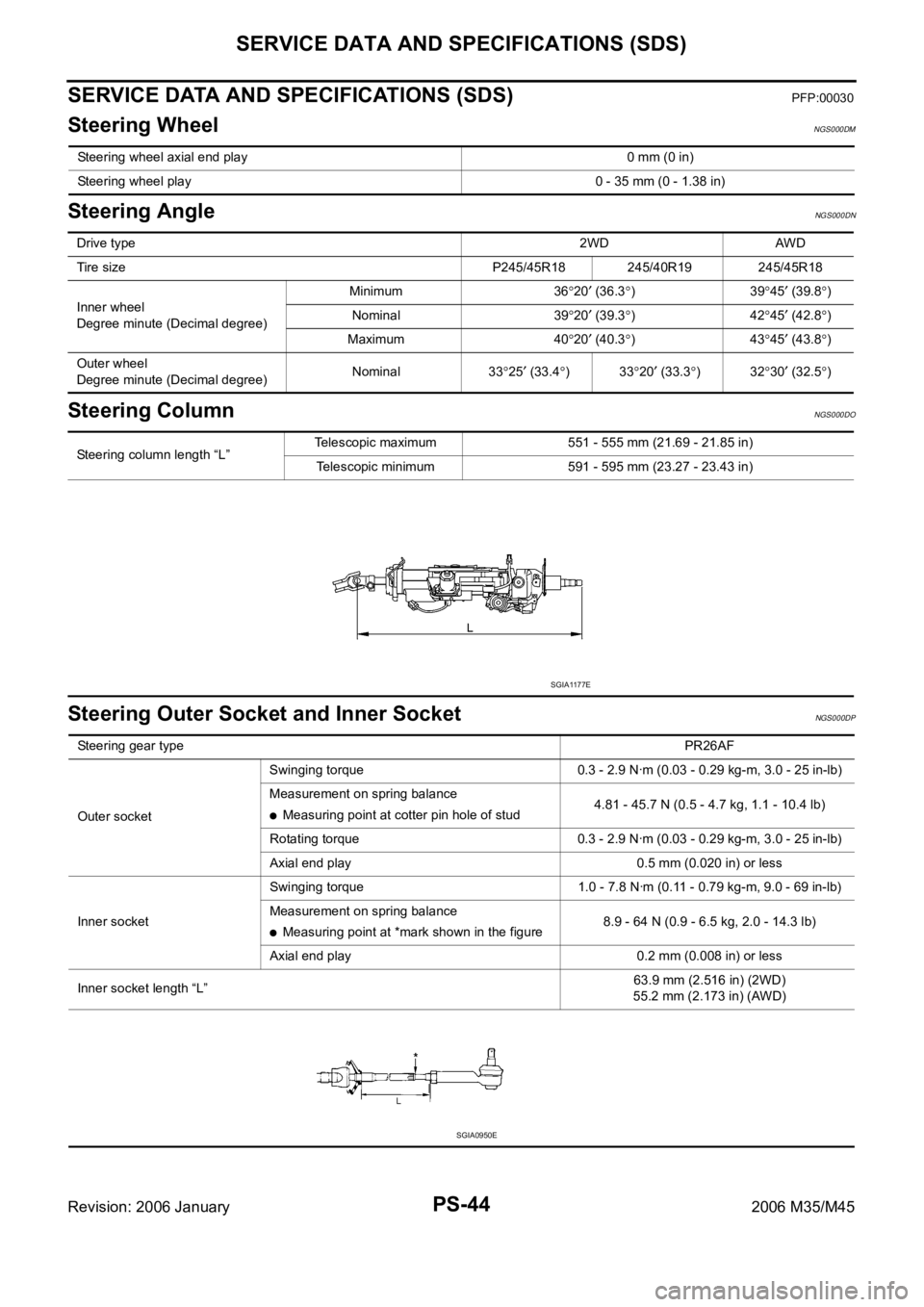
SERVICE DATA AND SPECIFICATIONS (SDS)PFP:00030
Steering WheelNGS000DM
Steering AngleNGS000DN
Steering ColumnNGS000DO
Steering Outer Socket and Inner SocketNGS000DP
Steering wheel axial end play 0 mm (0 in)
Steering wheel play 0 - 35 mm (0 - 1.38 in)
Drive type2WD AWD
Tire size P245/45R18 245/40R19 245/45R18
Inner wheel
Degree minute (Decimal degree)Minimum 36
20 (36.3)3945 (39.8)
Nominal 39
20 (39.3)4245 (42.8)
Maximum 40
20 (40.3)4345 (43.8)
Outer wheel
Degree minute (Decimal degree)Nominal 33
25 (33.4)3320 (33.3)3230 (32.5)
Steering column length “L”Telescopic maximum 551 - 555 mm (21.69 - 21.85 in)
Telescopic minimum 591 - 595 mm (23.27 - 23.43 in)
SGIA1177E
Steering gear typePR26AF
Outer socketSwinging torque 0.3 - 2.9 Nꞏm (0.03 - 0.29 kg-m, 3.0 - 25 in-lb)
Measurement on spring balance
Measuring point at cotter pin hole of stud4.81 - 45.7 N (0.5 - 4.7 kg, 1.1 - 10.4 lb)
Rotating torque 0.3 - 2.9 Nꞏm (0.03 - 0.29 kg-m, 3.0 - 25 in-lb)
Axial end play 0.5 mm (0.020 in) or less
Inner socketSwinging torque 1.0 - 7.8 Nꞏm (0.11 - 0.79 kg-m, 9.0 - 69 in-lb)
Measurement on spring balance
Measuring point at *mark shown in the figure8.9 - 64 N (0.9 - 6.5 kg, 2.0 - 14.3 lb)
Axial end play 0.2 mm (0.008 in) or less
Inner socket length “L”63.9 mm (2.516 in) (2WD)
55.2 mm (2.173 in) (AWD)
SGIA0950E
Page 4998 of 5621
SERVICE DATA AND SPECIFICATIONS (SDS)
PS-45
C
D
E
F
H
I
J
K
L
MA
B
PS
Revision: 2006 January2006 M35/M45
Steering GearNGS000DQ
Oil PumpNGS000DR
Steering FluidNGS000DS
Steering gear model PR26AF
Drive type 2WD AWD
Rack neutral position, dimension “L” (rack stroke) 68.5 mm (2.697 in) 67.0 mm (2.638 in)
SGIA0877E
Oil pump relief hydraulic pressure
8,520 - 9,320 kPa (86.9 - 95.1 kg/cm2 , 1,235 - 1,351 psi)
Fluid capacity
Approx. 1.0 (1-1/8 US qt, 7/8 Imp qt)
Page 4999 of 5621
PS-46
SERVICE DATA AND SPECIFICATIONS (SDS)
Revision: 2006 January2006 M35/M45
Page 5000 of 5621

RAX-1
REAR AXLE
D DRIVELINE/AXLE
CONTENTS
C
E
F
G
H
I
J
K
L
M
SECTION RAX
A
B
RAX
Revision: 2006 January2006 M35/M45
REAR AXLE
PRECAUTIONS .......................................................... 2
Caution ..................................................................... 2
PREPARATION ........................................................... 3
Special Service Tools [SST] ..................................... 3
Commercial Service Tools ........................................ 3
NOISE, VIBRATION AND HARSHNESS (NVH)
TROUBLESHOOTING ................................................ 4
NVH Troubleshooting Chart ..................................... 4
WHEEL HUB .............................................................. 5
On-Vehicle Inspection and Service .......................... 5
WHEEL BEARING INSPECTION ......................... 5
Removal and Installation .......................................... 5
COMPONENT ....................................................... 5
REMOVAL ........................................................
..... 5
INSPECTION AFTER REMOVAL ......................... 6
INSTALLATION ..................................................... 7REAR DRIVE SHAFT ................................................. 8
Removal and Installation .......................................... 8
COMPONENT ....................................................... 8
REMOVAL ........................................................
..... 8
INSPECTION AFTER REMOVAL ......................... 8
INSTALLATION ..................................................... 9
Disassembly and Assembly ...................................... 9
COMPONENT ....................................................... 9
DISASSEMBLY ..................................................... 9
INSPECTION AFTER DISASSEMBLY ................ 10
ASSEMBLY ......................................................... 11
SERVICE DATA ........................................................ 14
Wheel Bearing ........................................................ 14
Drive Shaft .............................................................. 14
Page 5001 of 5621
RAX-2
PRECAUTIONS
Revision: 2006 January2006 M35/M45
PRECAUTIONSPFP:00001
CautionNDS000FM
Observe the following precautions when disassembling and assembling drive shaft.
Joint sub-assembly does not disassemble because it is non-overhaul parts.
Perform work in a location which is as dust-free as possible.
Before disassembling and assembling, clean the outside of parts.
Prevention of the entry of foreign objects must be taken into account during disassembly of the service
location.
Disassembled parts must be carefully reassembled in the correct order. If work is interrupted, a clean
cover must be placed over parts.
Paper shop cloths must be used. Fabric shop cloths must not be used because of the danger of lint adher-
ing to parts.
Disassembled parts (except for rubber parts) should be cleaned with kerosene which shall be removed by
blowing with air or wiping with paper shop cloths.
Page 5002 of 5621
PREPARATION
RAX-3
C
E
F
G
H
I
J
K
L
MA
B
RAX
Revision: 2006 January2006 M35/M45
PREPARATIONPFP:00002
Special Service Tools [SST]NDS000FN
The actual shapes of Kent-Moore tools may differ from those of special service tools illustrated here.
Commercial Service ToolsNDS000FO
Tool number
(Kent-Moore No.)
Tool nameDescription
KV38100500
(—)
Drift
a: 80 mm (3.15 in) dia.
b: 60 mm (2.36 in) dia.Installing drive shaft plug
KV38102200
(—)
Drift
a: 90 mm (3.54 in) dia.
b: 31 mm (1.22 in) dia.Installing drive shaft plug
ZZA0701D
ZZA0920D
Tool nameDescription
Power tool
Removing wheel nuts
Removing brake caliper assembly
Removing suspension links
Removing drive shaft
PBIC0190E
Page 5004 of 5621

WHEEL HUB
RAX-5
C
E
F
G
H
I
J
K
L
MA
B
RAX
Revision: 2006 January2006 M35/M45
WHEEL HUBPFP:43202
On-Vehicle Inspection and ServiceNDS000FQ
Make sure the mounting conditions (looseness, back lash) of each component and component conditions
(wear, damage) are normal.
WHEEL BEARING INSPECTION
Move wheel hub and bearing assembly in the axial direction by hand. Make sure there is no looseness of
wheel bearing.
Rotate wheel hub, and make sure that is no unusual noise or other irregular conditions. If there is any of
irregular conditions, replace wheel hub and bearing assembly.
Removal and InstallationNDS000FR
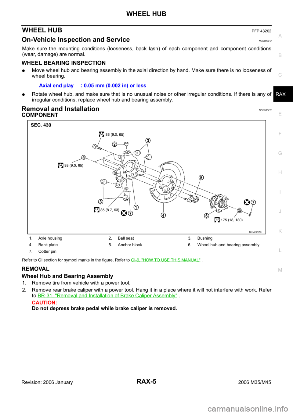
COMPONENT
Refer to GI section for symbol marks in the figure. Refer to GI-9, "HOW TO USE THIS MANUAL" .
REMOVAL
Wheel Hub and Bearing Assembly
1. Remove tire from vehicle with a power tool.
2. Remove rear brake caliper with a power tool. Hang it in a place where it will not interfere with work. Refer
to BR-31, "
Removal and Installation of Brake Caliper Assembly" .
CAUTION:
Do not depress brake pedal while brake caliper is removed. Axial end play : 0.05 mm (0.002 in) or less
1. Axle housing 2. Ball seat 3. Bushing
4. Back plate 5. Anchor block 6. Wheel hub and bearing assembly
7. Cotter pin
SDIA3251E
Page 5006 of 5621

WHEEL HUB
RAX-7
C
E
F
G
H
I
J
K
L
MA
B
RAX
Revision: 2006 January2006 M35/M45
INSTALLATION
Wheel Hub and Bearing Assembly
Installation is the reverse order of removal. For tightening torque refer to RAX-5, "COMPONENT" .
CAUTION:
Do not reuse non-reusable parts.
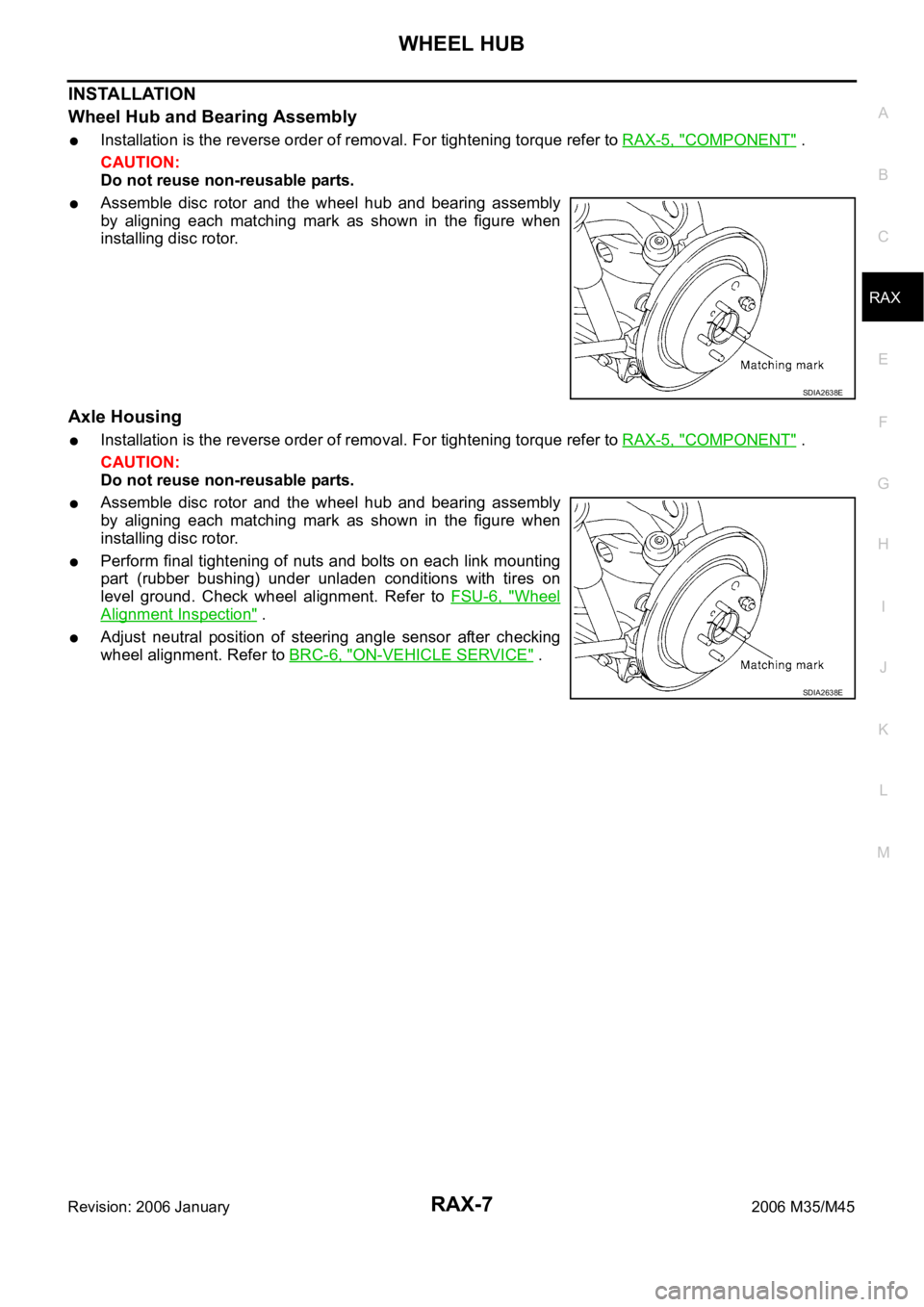
Assemble disc rotor and the wheel hub and bearing assembly
by aligning each matching mark as shown in the figure when
installing disc rotor.
Axle Housing
Installation is the reverse order of removal. For tightening torque refer to RAX-5, "COMPONENT" .
CAUTION:
Do not reuse non-reusable parts.
Assemble disc rotor and the wheel hub and bearing assembly
by aligning each matching mark as shown in the figure when
installing disc rotor.
Perform final tightening of nuts and bolts on each link mounting
part (rubber bushing) under unladen conditions with tires on
level ground. Check wheel alignment. Refer to FSU-6, "
Wheel
Alignment Inspection" .
Adjust neutral position of steering angle sensor after checking
wheel alignment. Refer to BRC-6, "
ON-VEHICLE SERVICE" .
SDIA2638E
SDIA2638E