2006 INFINITI M35 parking brake
[x] Cancel search: parking brakePage 3483 of 5621
GI-20
HOW TO USE THIS MANUAL
Revision: 2006 January2006 M35/M45
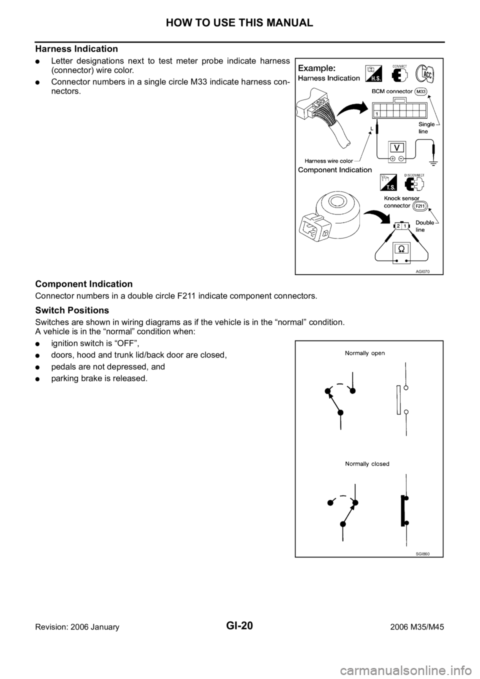
Harness Indication
Letter designations next to test meter probe indicate harness
(connector) wire color.
Connector numbers in a single circle M33 indicate harness con-
nectors.
Component Indication
Connector numbers in a double circle F211 indicate component connectors.
Switch Positions
Switches are shown in wiring diagrams as if the vehicle is in the “normal” condition.
A vehicle is in the “normal” condition when:
ignition switch is “OFF”,
doors, hood and trunk lid/back door are closed,
pedals are not depressed, and
parking brake is released.
AGI070
SGI860
Page 3647 of 5621
IDX-6
ALPHABETICAL INDEX
Meter ..................................................................... DI-5
METER - Wiring diagram .................................... DI-13
MIL data link connectors circuit ....... EC-722, EC-1459
MIL/DL - Wiring diagram .................. EC-722, EC-1459
MIRROR - Wiring diagram ................................ GW-99
Mirror, door ..................................................... GW-120
Mirror, out side ................................................ GW-120
Misfire .............................................. EC-361, EC-1084
MMSW - Wiring diagram .................................. AT-168
Mode door control linkage adjustment ATC-79, ATC-82
Mode door motor .............. ATC-75, ATC-80, ATC-140
Molding - See Exterior .............................. EI-25, EI-29
Mud guard - See Exterior .................................... EI-22
Multiport fuel injection (MFI) system .... EC-31, EC-741
Multiport fuel injection precautions ....................... GI-7
N
NATS - Wiring diagram .................................... BL-256
NONDTC - Wiring diagram .............................. AT-187
NVH troubleshooting (EM) .............................. EM-171
NVH troubleshooting (EM)(VQ35DE) ............... EM-12
NVH troubleshooting (Final drive) ......... FFD-6, RFD-7
NVH troubleshooting (Propeller shaft) ................. PR-3
NVH troubleshooting (Transfer) ........................... TF-8
NVIS (Nissan vehicle immobilizer system) precautions
GI-3
O
O2H2B1 - Wiring diagram .................. EC-191
, EC-913
O2H2B2 - Wiring diagram .................. EC-193, EC-915
O2S2B1 - Wiring diagram .. EC-289, EC-300, EC-313,
EC-1012
, EC-1023, EC-1036
O2S2B2 - Wiring diagram .. EC-291, EC-302, EC-315,
EC-1014
, EC-1025, EC-1038
Oil cooler (engine)(VQ35DE) ............................. LU-14
Oil filter(VK45DE) .............................................. LU-29
Oil filter(VQ35DE) .............................................. LU-10
Oil pan (engine)(VK45DE) .............................. EM-187
Oil pan (engine)(VQ35DE) ................................ EM-29
Oil pressure (engine)(VK45DE) ......................... LU-26
Oil pressure (engine)(VQ35DE) ........................... LU-8
Oil pressure relief valve (engine)(VQ35DE) ........ LU-6
Oil pump (A/T) ................................................. AT-318
Oil pump (engine)(VK45DE) .............................. LU-30
Oil pump (engine)(VQ35DE) .............................. LU-18
Oil pump regulator valve (engine)(VK45DE) ..... LU-30
Oil pump regulator valve (engine)(VQ35DE) ..... LU-18
Oil seal replacement (engine)(VK45DE) ......... EM-229
Oil seal replacement (engine)(VQ35DE) .......... EM-98
Oil seal replacement (front of final drive) .......... FFD-9,
RFD-10
Oil seal replacement (side of final drive) ......... FFD-11,
RFD-14
On board diagnostic system ................ EC-54, EC-764
ORVR (On-board Refueling Vapor Recovery) .. EC-46,
EC-756
Out side mirror ................................................ GW-120
Overheat ......................................... EC-512, EC-1239
P
P/SCKT - Wiring diagram ................................ WW-51
Park/Neutral position switch ........... EC-504, EC-1223
Park/neutral position switch (A/T) .................... AT-113
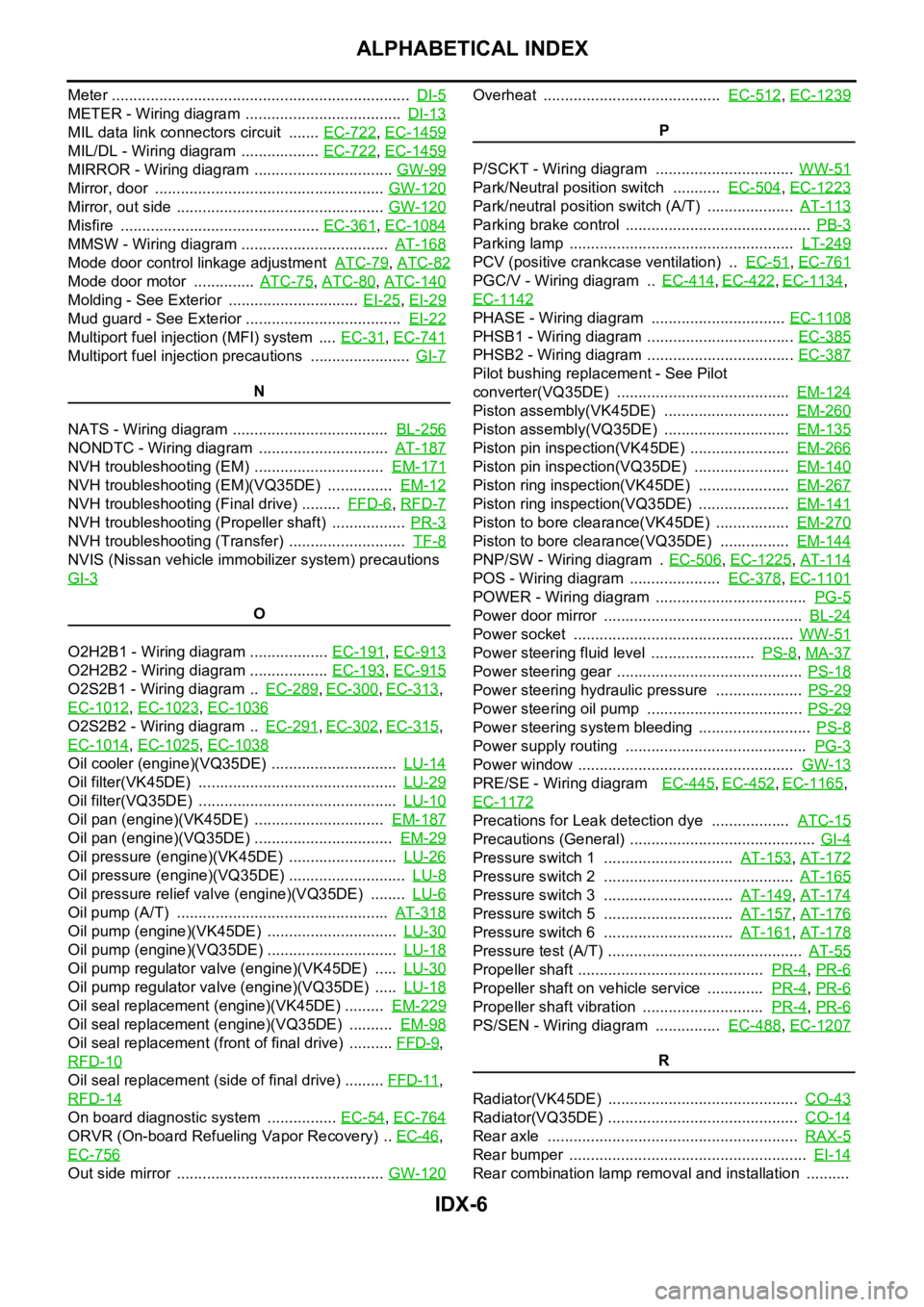
Parking brake control ........................................... PB-3
Parking lamp .................................................... LT-249
PCV (positive crankcase ventilation) .. EC-51, EC-761
PGC/V - Wiring diagram .. EC-414, EC-422, EC-1134,
EC-1142
PHASE - Wiring diagram ............................... EC-1108
PHSB1 - Wiring diagram .................................. EC-385
PHSB2 - Wiring diagram .................................. EC-387
Pilot bushing replacement - See Pilot
converter(VQ35DE) ........................................ EM-124
Piston assembly(VK45DE) ............................. EM-260
Piston assembly(VQ35DE) ............................. EM-135
Piston pin inspection(VK45DE) ....................... EM-266
Piston pin inspection(VQ35DE) ...................... EM-140
Piston ring inspection(VK45DE) ..................... EM-267
Piston ring inspection(VQ35DE) ..................... EM-141
Piston to bore clearance(VK45DE) ................. EM-270
Piston to bore clearance(VQ35DE) ................ EM-144
PNP/SW - Wiring diagram . EC-506, EC-1225, AT-114
POS - Wiring diagram ..................... EC-378, EC-1101
POWER - Wiring diagram ................................... PG-5
Power door mirror .............................................. BL-24
Power socket ................................................... WW-51
Power steering fluid level ........................ PS-8, MA-37
Power steering gear ........................................... PS-18
Power steering hydraulic pressure .................... PS-29
Power steering oil pump .................................... PS-29
Power steering system bleeding .......................... PS-8
Power supply routing .......................................... PG-3
Power window .................................................. GW-13
PRE/SE - Wiring diagram EC-445, EC-452, EC-1165,
EC-1172
Precations for Leak detection dye .................. ATC-15
Precautions (General) ........................................... GI-4
Pressure switch 1 .............................. AT-153, AT-172
Pressure switch 2 ............................................ AT-165
Pressure switch 3 .............................. AT-149, AT-174
Pressure switch 5 .............................. AT-157, AT-176
Pressure switch 6 .............................. AT-161, AT-178
Pressure test (A/T) ............................................. AT-55
Propeller shaft ........................................... PR-4, PR-6
Propeller shaft on vehicle service ............. PR-4, PR-6
Propeller shaft vibration ............................ PR-4, PR-6
PS/SEN - Wiring diagram ............... EC-488, EC-1207
R
Radiator(VK45DE) ............................................ CO-43
Radiator(VQ35DE) ............................................ CO-14
Rear axle .......................................................... RAX-5
Rear bumper ....................................................... EI-14
Rear combination lamp removal and installation ..........
Page 3711 of 5621
![INFINITI M35 2006 Factory Service Manual LAN-42
[CAN]
CAN COMMUNICATION
Revision: 2006 January2006 M35/M45
Distance to empty signalTR
Fuel level low warning signal T R
Fuel level sensor signal R T
Manual mode shift down signal R T
Manual mod INFINITI M35 2006 Factory Service Manual LAN-42
[CAN]
CAN COMMUNICATION
Revision: 2006 January2006 M35/M45
Distance to empty signalTR
Fuel level low warning signal T R
Fuel level sensor signal R T
Manual mode shift down signal R T
Manual mod](/manual-img/42/57023/w960_57023-3710.png)
LAN-42
[CAN]
CAN COMMUNICATION
Revision: 2006 January2006 M35/M45
Distance to empty signalTR
Fuel level low warning signal T R
Fuel level sensor signal R T
Manual mode shift down signal R T
Manual mode shift up signal R T
Manual mode signal R T
Not manual mode signal R T
Parking brake switch signal R T
Seat belt buckle switch signal R T
Stop lamp switch signalRT
TR
TR
Target A/C evaporator temperature signal R T
A/C switch/indicator signalRT
TR
System setting signalRT R
TR T
RAS signalTR
A/T shift schedule change demand signal R T
ABS malfunction signalTR
ABS operation signal TR
ABS warning lamp signal R T
Brake pressure control signalTR
Brake warning lamp signal R T
Side G sensor signal R T
SLIP indicator lamp signal R T
TCS malfunction signalTR
TCS operation signal TR
VDC malfunction signalTR
VDC OFF indicator lamp signal R T
VDC OFF switch signalTR
VDC operation signalTR
Vehicle speed signalRR R R R T R
RRRR R T R RR R Signals
ECM
TCM
AFS control unit*1
BCM
LDW camera unit*2
Low tire pressure warning control unit
Steering angle sensor
Intelligent Key unit
Unified meter and A/C amp.
AV (NAVI) control unit
RAS control unit*3
Pre-crash seat belt control unit*4
Driver seat control unit
ABS actuator and electric unit (control unit)
ICC sensor integrated unit*5
IPDM E/R
Page 3715 of 5621
![INFINITI M35 2006 Factory Service Manual LAN-46
[CAN]
CAN COMMUNICATION
Revision: 2006 January2006 M35/M45
A/C evaporator temperature signal R T
Distance to empty signalTR
Fuel level low warning signalTR
Fuel level sensor signal R T
Manual m INFINITI M35 2006 Factory Service Manual LAN-46
[CAN]
CAN COMMUNICATION
Revision: 2006 January2006 M35/M45
A/C evaporator temperature signal R T
Distance to empty signalTR
Fuel level low warning signalTR
Fuel level sensor signal R T
Manual m](/manual-img/42/57023/w960_57023-3714.png)
LAN-46
[CAN]
CAN COMMUNICATION
Revision: 2006 January2006 M35/M45
A/C evaporator temperature signal R T
Distance to empty signalTR
Fuel level low warning signalTR
Fuel level sensor signal R T
Manual mode shift down signal R T
Manual mode shift up signal R T
Manual mode signal R T
Not manual mode signal R T
Parking brake switch signal R R T
Seat belt buckle switch signal R T
Snow mode switch signalRT
TRR
Stop lamp switch signalRR T
TR
TR
Target A/C evaporator temperature signal R T
A/C switch/indicator signalRT
TR
System setting signalRTR
TRT
A/T shift schedule change demand signal R T
ABS malfunction signalTR
ABS operation signal TR
ABS warning lamp signalRT
Brake pressure control signalTR
Brake warning lamp signalRT
Side G sensor signal R T
SLIP indicator lamp signalRT
TCS malfunction signalTR
TCS operation signal TR
VDC malfunction signalTR
VDC OFF indicator lamp signal R T
VDC OFF switch signalTR
VDC operation signalTR Signals
ECM
TCM
AWD control unit
AFS control unit*1
BCM
LDW camera unit*2
Low tire pressure warning control unit
Steering angle sensor
Intelligent Key unit
Unified meter and A/C amp.
AV (NAVI) control unit
Pre-crash seat belt control unit*3
Driver seat control unit
ABS actuator and electric unit (control unit)
ICC sensor integrated unit*4
IPDM E/R
Page 4429 of 5621

LT-2Revision: 2006 January2006 M35/M45 ACTIVE TEST ..................................................... 59
CONSULT-II Functions (IPDM E/R) ........................ 60
CONSULT-II BASIC OPERATION ....................... 60
DATA MONITOR .................................................. 61
ACTIVE TEST ..................................................... 61
Headlamp High Beam Does Not Illuminate (Both
Sides) ..................................................................... 62
Headlamp High Beam Does Not Illuminate (One
Side) ....................................................................... 65
High Beam Indicator Lamp Does Not Illuminate ..... 66
Headlamp Low Beam Does Not Illuminate (Both
Sides) ..................................................................... 67
Headlamp Low Beam Does Not Illuminate (One
Side) ....................................................................... 70
Headlamps Do Not Turn OFF ................................. 72
General Information for Xenon Headlamp Trouble
Diagnosis ................................................................ 73
Caution: .................................................................. 73
Xenon Headlamp Trouble Diagnosis ...................... 73
Aiming Adjustment .................................................. 74
PREPARATION BEFORE ADJUSTING .............. 74
LOW BEAM AND HIGH BEAM ........................... 74
ADJUSTMENT USING AN ADJUSTMENT
SCREEN (LIGHT/DARK BORDERLINE) ............ 75
Bulb Replacement ...............................................
... 75
HEADLAMP (INNER) HIGH BEAM ..................... 75
HEADLAMP (OUTER) LOW BEAM .................... 76
PARKING LAMP (CLEARANCE LAMP) .............. 76
FRONT TURN SIGNAL LAMP ............................ 76
FRONT SIDE MARKER LAMP ............................ 76
Removal and Installation ........................................ 76
Disassembly and Assembly .................................... 77
DISASSEMBLY ................................................... 77
ASSEMBLY ......................................................... 78
HEADLAMP (FOR CANADA) - DAYTIME LIGHT
SYSTEM - .................................................................. 79
Component Parts and Harness Connector Location ... 79
System Description ................................................. 79
OUTLINE ............................................................. 80
HEADLAMP OPERATION ................................... 81
DAYTIME LIGHT OPERATION ........................... 82
COMBINATION SWITCH READING FUNCTION ... 82
AUTO LIGHT OPERATION ................................. 82
CAN Communication System Description .............. 82
Schematic ............................................................... 83
Wiring Diagram — DTRL — ................................... 84
Terminals and Reference Values for BCM .............. 89
Terminals and Reference Values for IPDM E/R ...... 91
How to Perform Trouble Diagnosis ......................... 91
Preliminary Check .................................................. 92
INSPECTION FOR POWER SUPPLY AND
GROUND CIRCUIT ............................................. 92
INSPECTION FOR PARKING BRAKE SWITCH
CIRCUIT .............................................................. 93
CONSULT-II Functions (BCM) ................................ 94
CONSULT-II BASIC OPERATION ....................... 94
DATA MONITOR .................................................. 95
ACTIVE TEST ..................................................... 96
CONSULT-II Functions (IPDM E/R) ........................ 97CONSULT-II BASIC OPERATION ....................... 97
DATA MONITOR .................................................. 98
ACTIVE TEST ...................................................... 98
Daytime Light Control Does Not Operate Properly
(Normal Headlamps Operate Properly) .................. 99
Headlamp High Beam Does Not Illuminate (Both
Sides) ....................................................................102
RH High Beam Does Not Illuminate But LH High
Beam Illuminates ..................................................105
LH High Beam Does Not Illuminate But RH High
Beam Illuminates ..................................................107
Headlamp Low Beam Does Not Illuminate (Both
Sides) ....................................................................109
Headlamp Low Beam Does Not Illuminate (One
Side) ......................................................................112
Headlamps Do Not Turn OFF ...............................114
General Information for Xenon Headlamp Trouble
Diagnosis ..............................................................115
CAUTION: .............................................................115
Xenon Headlamp Trouble Diagnosis ....................115
Aiming Adjustment ................................................115
Bulb Replacement .................................................115
Removal and Installation .......................................115
Disassembly and Assembly ..................................115
AUTO LIGHT SYSTEM ...........................................116
Component Parts and Harness Connector Location .116
System Description ...............................................116
OUTLINE ...........................................................116
COMBINATION SWITCH READING FUNCTION .117
EXTERIOR LAMP BATTERY SAVER CONTROL .117
DELAY TIMER FUNCTION ................................117
CAN Communication System Description ............117
CAN Communication Unit .....................................117
Major Components and Functions ........................117
Schematic .............................................................118
Wiring Diagram — AUTO/L — ..............................119
Terminals and Reference Values for BCM ............123
Terminals and Reference Values for IPDM E/R ....125
How to Perform Trouble Diagnoses ......................125
Preliminary Check .................................................126
SETTING CHANGE FUNCTIONS .....................126
CHECK POWER SUPPLY AND GROUND CIR-
CUIT ...................................................................126
CONSULT-II Functions (BCM) .............................
.127
CONSULT-II BASIC OPERATION .....................127
WORK SUPPORT .............................................128
DATA MONITOR ................................................129
ACTIVE TEST ....................................................130
Symptom Chart .....................................................130
Lighting Switch Inspection ....................................131
Optical Sensor System Inspection ........................131
Removal and Installation for Optical Sensor .........133
REMOVAL ..........................................................133
INSTALLATION ..................................................133
ACTIVE AFS ............................................................134
Component Parts and Harness Connector Location .134
System Description ...............................................135
AFS (ADAPTIVE FRONT-LIGHTING SYSTEM) .135
HEADLAMP AUTO AIMING ..............................136
Page 4506 of 5621
HEADLAMP (FOR CANADA) - DAYTIME LIGHT SYSTEM -
LT-79
C
D
E
F
G
H
I
J
L
MA
B
LT
Revision: 2006 January2006 M35/M45
HEADLAMP (FOR CANADA) - DAYTIME LIGHT SYSTEM -PFP:26010
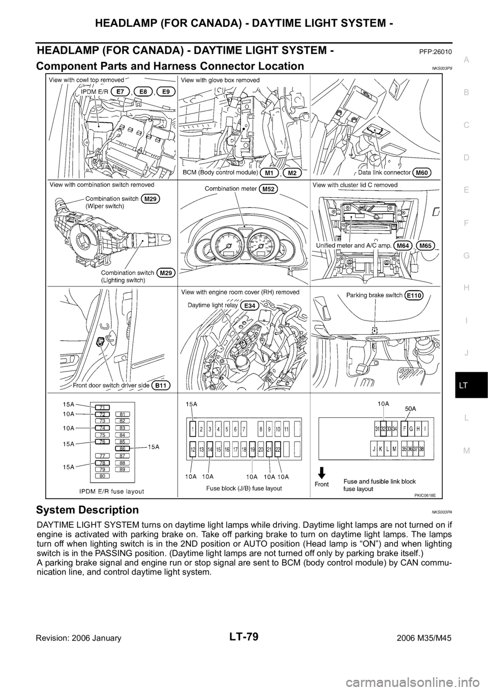
Component Parts and Harness Connector LocationNKS003P9
System DescriptionNKS003PA
DAYTIME LIGHT SYSTEM turns on daytime light lamps while driving. Daytime light lamps are not turned on if
engine is activated with parking brake on. Take off parking brake to turn on daytime light lamps. The lamps
turn off when lighting switch is in the 2ND position or AUTO position (Head lamp is “ON”) and when lighting
switch is in the PASSING position. (Daytime light lamps are not turned off only by parking brake itself.)
A parking brake signal and engine run or stop signal are sent to BCM (body control module) by CAN commu-
nication line, and control daytime light system.
PKIC0618E
Page 4509 of 5621
LT-82
HEADLAMP (FOR CANADA) - DAYTIME LIGHT SYSTEM -
Revision: 2006 January2006 M35/M45
DAYTIME LIGHT OPERATION
With the engine running, the lighting switch in the OFF or AUTO position (headlamp is not illuminate) and
parking brake released, the IPDM E/R receives input request signal from BCM to turn on daytime light. This
input is communicated across the CAN communication lines. The CPU of the IPDM E/R controls the daytime
light relay coil. When energized, this relay directs power
through daytime light relay terminals 5 and 3
through front combination lamp RH terminal 2
through front combination lamp RH terminal 6
through IPDM E/R terminal 27
through 10A fuse (No. 72, located in IPDM E/R)
through 10A fuse (No. 74, located in IPDM E/R)
through IPDM E/R terminal 28
to front combination lamp LH terminal 6.
Ground is supplied
to combination lamp LH terminal 2
through grounds E22 and E43.
With power and grounds supplied, the daytime lights illuminate. The high beam headlamps are now wired in
series and illuminate at a reduced intensity.
COMBINATION SWITCH READING FUNCTION
Refer to BCS-3, "COMBINATION SWITCH READING FUNCTION" .
AUTO LIGHT OPERATION
For auto light operation, refer to LT- 11 6 , "System Description" .
CAN Communication System DescriptionNKS003PB
Refer to LAN-34, "CAN COMMUNICATION" .
Page 4518 of 5621
HEADLAMP (FOR CANADA) - DAYTIME LIGHT SYSTEM -
LT-91
C
D
E
F
G
H
I
J
L
MA
B
LT
Revision: 2006 January2006 M35/M45
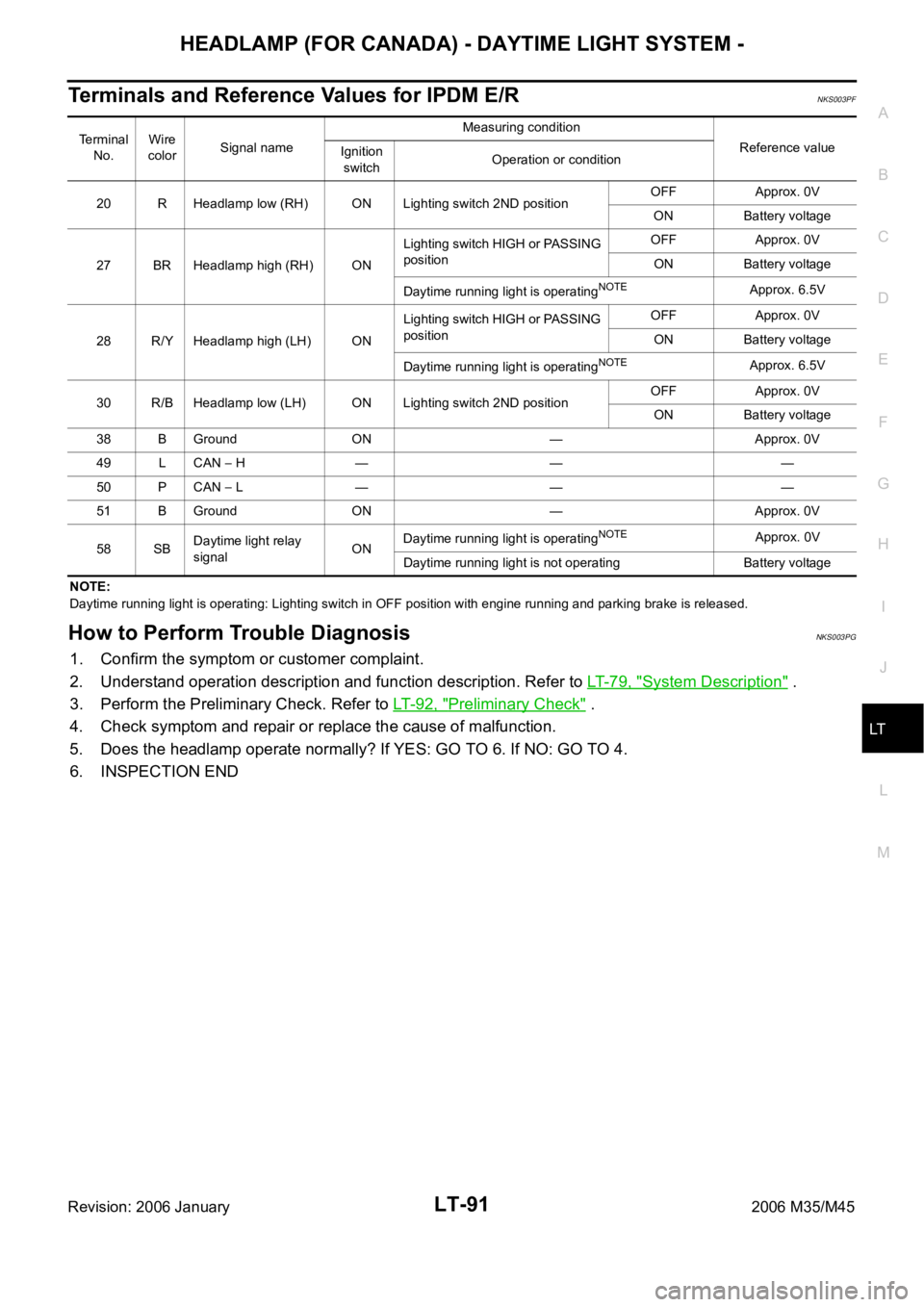
Terminals and Reference Values for IPDM E/RNKS003PF
NOTE:
Daytime running light is operating: Lighting switch in OFF position with engine running and parking brake is released.
How to Perform Trouble DiagnosisNKS003PG
1. Confirm the symptom or customer complaint.
2. Understand operation description and function description. Refer to LT- 7 9 , "
System Description" .
3. Perform the Preliminary Check. Refer to LT-92, "
Preliminary Check" .
4. Check symptom and repair or replace the cause of malfunction.
5. Does the headlamp operate normally? If YES: GO TO 6. If NO: GO TO 4.
6. INSPECTION END
Terminal
No.Wire
colorSignal nameMeasuring condition
Reference value
Ignition
switchOperation or condition
20 R Headlamp low (RH) ON Lighting switch 2ND positionOFF Approx. 0V
ON Battery voltage
27 BR Headlamp high (RH) ONLighting switch HIGH or PASSING
positionOFF Approx. 0V
ON Battery voltage
Daytime running light is operating
NOTEApprox. 6.5V
28 R/Y Headlamp high (LH) ONLighting switch HIGH or PASSING
positionOFF Approx. 0V
ON Battery voltage
Daytime running light is operating
NOTEApprox. 6.5V
30 R/B Headlamp low (LH) ON Lighting switch 2ND positionOFF Approx. 0V
ON Battery voltage
38 B Ground ON — Approx. 0V
49 L CAN
H — — —
50 P CAN
L — — —
51 B Ground ON — Approx. 0V
58 SBDaytime light relay
signalONDaytime running light is operating
NOTEApprox. 0V
Daytime running light is not operating Battery voltage