2006 INFINITI M35 Body
[x] Cancel search: BodyPage 987 of 5621

BL-48
INTELLIGENT KEY SYSTEM
Revision: 2006 January2006 M35/M45
System DescriptionNIS001X8
The Intelligent Key system is a system that makes it possible to lock and unlock the door locks (door lock/
unlock function), open the trunk (trunk open function), and start the engine (engine start function) by carry-
ing around the Intelligent Key (without some key operation), which operates based on the results of elec-
tronic ID verification using two-way communications between the Intelligent Key and the vehicle
(Intelligent Key unit).
CAUTION:
The driver should always carry the Intelligent Key
Operation of the remote controller buttons on the Intelligent Key also provides the same functions as the
remote controller entry system. (Remote keyless entry functions)
If an action that does not meet the operating conditions of the Intelligent Key system is taken, the buzzer
goes off to inform the driver. (Warning chime functions)
When a door lock is locked, unlocked or trunk open with request switch or remote controller button opera-
tion, the hazard lamps flash and the Intelligent Key warning buzzer or horn sounds (Hazard and buzzer/
horn reminder function).
Even if the Intelligent Key battery is completely discharged, the door locks can be locked and unlocked
with the mechanical key built into the Intelligent Key, and then initiates engine by inserting Intelligent Key
into key slot.
The settings for each function can be changed with the CONSULT-II.
If an Intelligent Key is lost, a new Intelligent Key can be registered. A maximum of 4 Intelligent Keys can
be registered.
It has been made possible to diagnose the system and register an Intelligent Key with the CONSULT-II.
DOOR LOCK/UNLOCK/TRUNK OPEN FUNCTION
Only when pressing the request switch, it is possible to lock and unlock the door and open the trunk by carry-
ing around the Intelligent Key (without some key operation).
System Diagram
Operation Description/Door Lock/Unlock
When the Intelligent Key unit detects that each door request switch is pressed, it starts the outside key
antenna and inside key antenna corresponding to the pressed door request switch and sends the request
signal to the Intelligent Key. And then, make sure that the Intelligent Key is near the door.
If the Intelligent Key is within the outside key antenna detection area, it receives the request signal and
sends the key ID signal to the Intelligent Key unit via remote keyless entry receiver.
Intelligent Key unit receives the key ID signal and compares it with the registered key ID.
If the key ID check result is OK, the Intelligent Key unit sends the door lock/unlock request signal to BCM
(Body control module) via CAN communication line.
Intelligent Key unit sends the door lock/unlock signal and sounds Intelligent Key buzzer warning (lock: 1
time, unlock: 2 times) at the same time.
PIIB6273E
Page 988 of 5621

INTELLIGENT KEY SYSTEM
BL-49
C
D
E
F
G
H
J
K
L
MA
B
BL
Revision: 2006 January2006 M35/M45
When BCM receives the door lock/unlock signal, it operates door lock actuator and flashes the hazard
lamp (lock: 1 time, unlock: 2 times) at the same time as a reminder.
Operation Description/Trunk Open
When the Intelligent Key unit detects that trunk open request switch is pressed, it starts the outside key
antenna (trunk room) and inside key antenna corresponding to the pressed trunk open request switch and
sends the request signal to the Intelligent Key. And then, make sure that the Intelligent Key is near the
trunk.
If the Intelligent Key is within the outside key antenna (trunk room) detection area, it receives the request
signal and sends the key ID signal to the Intelligent Key unit via remote keyless entry receiver.
Intelligent Key unit receives the key ID signal and compares it with the registered key ID.
If the key ID check result is OK, the Intelligent Key unit sends trunk open request signal to BCM (Body
control module) via CAN communication line.
Intelligent Key unit sends the trunk open request signal and sounds Intelligent Key warning buzzer 4 times
at the same time.
When BCM receives the trunk open request signal, it operates the trunk lid opener actuator and opens the
trunk.
Operation Condition
If the following conditions are not satisfied, door lock/unlock or trunk open operations are not performed even
if the request switch is operated.
*: Even with a registered Intelligent Key remain inside the vehicle, door locks can be unlock from outside of the vehicle with a spare Intel-
ligent Key as long as key IDs are different.
Outside Key Antenna Detection Area
The outside key antenna detection area of door lock/unlock function
is in the range of approximately 80 cm (31.50 in) surrounding the
driver and passenger door handles (1). The outside key antenna
detection area of trunk open function is in the range of approximately
80 cm (31.50 in) surrounding Trunk opener request switch (2). How-
ever, this operating range depends on the ambient conditions.
Each request switch operation Operation condition
Lock operation
All doors are closed
Ignition switch is in OFF position
Intelligent Key is out of key slot
Intelligent Key is outside the vehicle
Intelligent Key is within outside key antenna detection area
Unlock Operation
Intelligent Key is outside the vehicle
Intelligent Key is within outside key antenna detection area *
Trunk open operation
Intelligent Key is within outside key antenna (trunk room) detection area*
Trunk cancel switch is ON
Key reminder functions operate (trunk)
PIIB5899E
Page 1130 of 5621
DOOR
BL-191
C
D
E
F
G
H
J
K
L
MA
B
BL
Revision: 2006 January2006 M35/M45
2. Accessing from inside the vehicle, loosen the mounting nuts. Open the rear door, and raise the rear door
at rear end to adjust.
STRIKER ADJUSTMENT
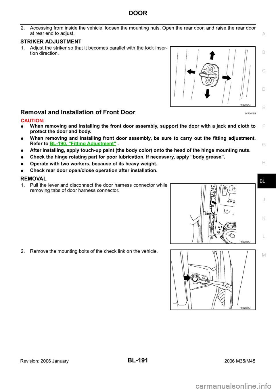
1. Adjust the striker so that it becomes parallel with the lock inser-
tion direction.
Removal and Installation of Front DoorNIS001ZA
CAUTION:
When removing and installing the front door assembly, support the door with a jack and cloth to
protect the door and body.
When removing and installing front door assembly, be sure to carry out the fitting adjustment.
Refer to BL-190, "
Fitting Adjustment" .
After installing, apply touch-up paint (the body color) onto the head of the hinge mounting nuts.
Check the hinge rotating part for poor lubrication. If necessary, apply “body grease”.
Operate with two workers, because of its heavy weight.
Check rear door open/close operation after installation.
REMOVAL
1. Pull the lever and disconnect the door harness connector while
removing tabs of door harness connector.
2. Remove the mounting bolts of the check link on the vehicle.
PIIB2804J
PIIB3884J
PIIB2865J
Page 1131 of 5621
BL-192
DOOR
Revision: 2006 January2006 M35/M45
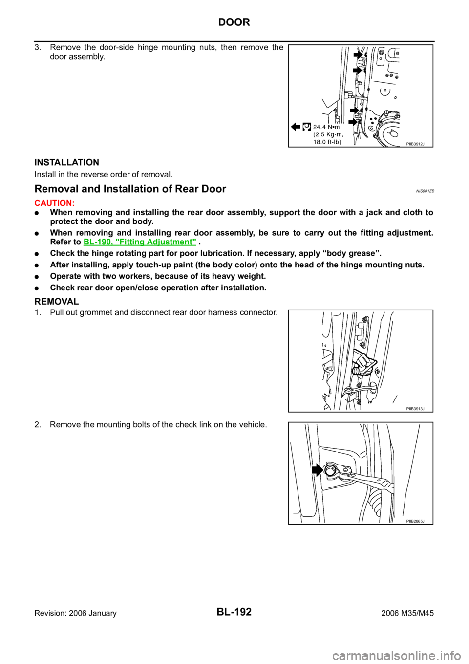
3. Remove the door-side hinge mounting nuts, then remove the
door assembly.
INSTALLATION
Install in the reverse order of removal.
Removal and Installation of Rear DoorNIS001ZB
CAUTION:
When removing and installing the rear door assembly, support the door with a jack and cloth to
protect the door and body.
When removing and installing rear door assembly, be sure to carry out the fitting adjustment.
Refer to BL-190, "
Fitting Adjustment" .
Check the hinge rotating part for poor lubrication. If necessary, apply “body grease”.
After installing, apply touch-up paint (the body color) onto the head of the hinge mounting nuts.
Operate with two workers, because of its heavy weight.
Check rear door open/close operation after installation.
REMOVAL
1. Pull out grommet and disconnect rear door harness connector.
2. Remove the mounting bolts of the check link on the vehicle.
PIIB3912J
PIIB3913J
PIIB2865J
Page 1143 of 5621
BL-204
TRUNK LID
Revision: 2006 January2006 M35/M45
Loosen the striker mounting bolts.
Lift up the trunk lid approx. 100 - 150 mm (3.94 - 5.91 in) height then close it lightly and make sure it
engaged firmly with the trunk lid closed.
Check the clearance and evenness.
Finally tighten the trunk lid striker.
Removal and Installation of Trunk Lid AssemblyNIS001ZI
CAUTION:
After installing, apply touch-up paint (the body color) onto the head of the hinge mounting bolts.
After installing, check operation.
After installing, perform fitting adjustment. Refer to BL-203, "Fitting Adjustment" .
REMOVAL
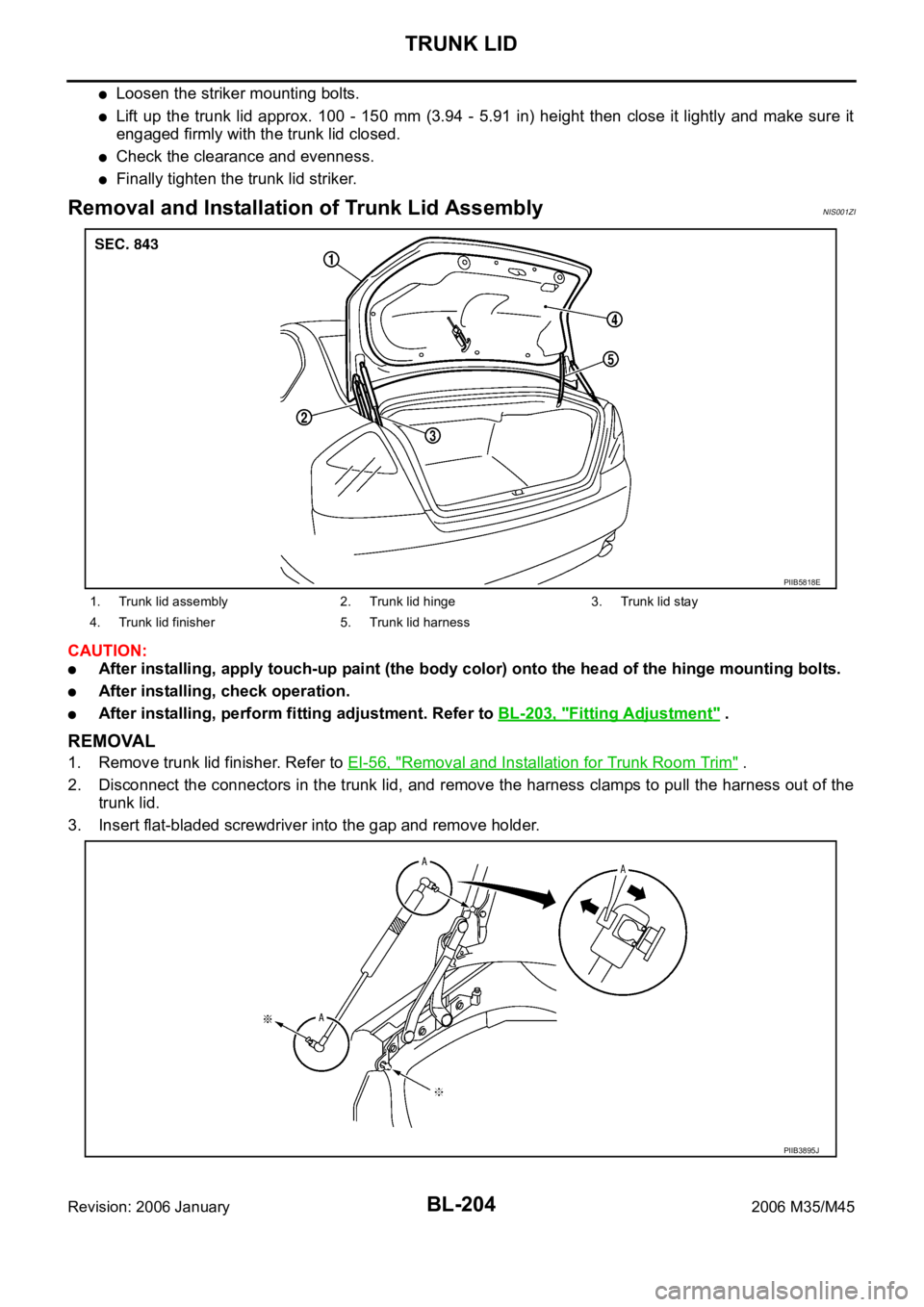
1. Remove trunk lid finisher. Refer to EI-56, "Removal and Installation for Trunk Room Trim" .
2. Disconnect the connectors in the trunk lid, and remove the harness clamps to pull the harness out of the
trunk lid.
3. Insert flat-bladed screwdriver into the gap and remove holder.
1. Trunk lid assembly 2. Trunk lid hinge 3. Trunk lid stay
4. Trunk lid finisher 5. Trunk lid harness
PIIB5818E
PIIB3895J
Page 1144 of 5621
TRUNK LID
BL-205
C
D
E
F
G
H
J
K
L
MA
B
BL
Revision: 2006 January2006 M35/M45
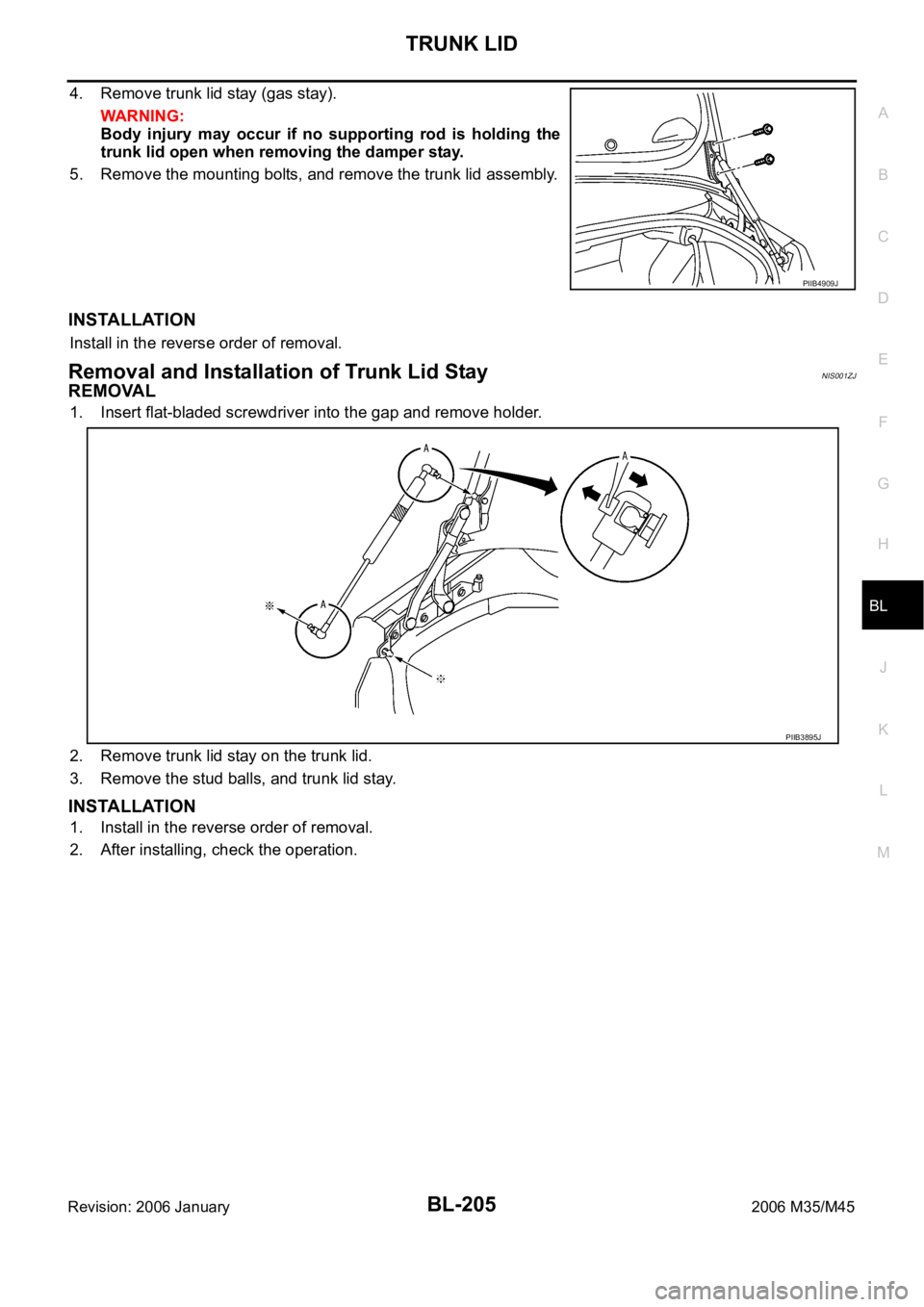
4. Remove trunk lid stay (gas stay).
WAR NING :
Body injury may occur if no supporting rod is holding the
trunk lid open when removing the damper stay.
5. Remove the mounting bolts, and remove the trunk lid assembly.
INSTALLATION
Install in the reverse order of removal.
Removal and Installation of Trunk Lid StayNIS001ZJ
REMOVAL
1. Insert flat-bladed screwdriver into the gap and remove holder.
2. Remove trunk lid stay on the trunk lid.
3. Remove the stud balls, and trunk lid stay.
INSTALLATION
1. Install in the reverse order of removal.
2. After installing, check the operation.
PIIB4909J
PIIB3895J
Page 1147 of 5621
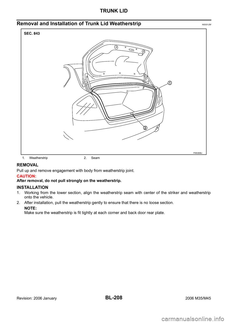
BL-208
TRUNK LID
Revision: 2006 January2006 M35/M45
Removal and Installation of Trunk Lid WeatherstripNIS001ZM
REMOVAL
Pull up and remove engagement with body from weatherstrip joint.
CAUTION:
After removal, do not pull strongly on the weatherstrip.
INSTALLATION
1. Working from the lower section, align the weatherstrip seam with center of the striker and weatherstrip
onto the vehicle.
2. After installation, pull the weatherstrip gently to ensure that there is no loose section.
NOTE:
Make sure the weatherstrip is fit tightly at each corner and back door rear plate.
1. Weatherstrip 2. Seam
PIIB3898J
Page 1149 of 5621

BL-210
TRUNK LID OPENER
Revision: 2006 January2006 M35/M45
System DescriptionNIS001ZO
Power is supplied at all times
through 50A fusible link (letter F, located in the fuse and fusible link box)
to BCM terminal 55,
through 10A fuse [No.21, located in the fuse block (J/B)]
to BCM terminal 42.
Ground is supplied
to BCM terminal 52
through body grounds M16 and M70.
When trunk lid opener cancel switch is ON and trunk lid opener switch is ON (pushed)
Ground is supplied
to BCM terminal 30
through trunk lid opener switch terminals 1and 2
through trunk lid opener cancel switch terminals 1and 3 and
through body grounds M16 and M70.
And power is supplied
through BCM terminal 68
to trunk lid opener actuator terminal 3.
Ground is supplied
to trunk lid opener actuator terminal 2
through body grounds B5, B40 and B131.
Then BCM open trunk lid opener actuator.
TRUNK LID OPENER OPERATION
When trunk lid opener switch or trunk button of Intelligent Key is ON, BCM opens trunk opener actuator.
BCM can open trunk lid opener actuator when
vehicle speed is less than 5 km/h (3MPH)
vehicle security system is disarmed or pre-armed phase
BCM does not open trunk lid opener actuator when
trunk lid opener cancel switch is OFF (CANSEL)
vehicle speed is more than 5 km/h (3MPH)
vehicle security system is armed or alarm phase
Intelligent Key is inserted in key slot