Page 1162 of 5621

VEHICLE SECURITY (THEFT WARNING) SYSTEM
BL-223
C
D
E
F
G
H
J
K
L
MA
B
BL
Revision: 2006 January2006 M35/M45
POWER SUPPLY AND GROUND CIRCUIT
Power is supplied at all times
through 50A fusible link (letter F , located in the fuse and fusible link box)
to BCM terminal 55,
through 10A fuse [No. 21, located in the fuse block (J/B)]
to BCM terminal 42,
through 10A fuse [No. 71, located in the IPDM E/R]
to IPDM E/R internal CPU,
through 15A fuse [No. 78, located in the IPDM E/R]
to IPDM E/R internal CPU,
through 15A fuse [No. 37, located in the fuse block (J/B)]
to multi-function switch (security indicator) terminal 1.
With the ignition switch in the ACC or ON position, power is supplied
through 10A fuse [No. 6, located in the fuse block (J/B)]
to BCM terminal 11.
Ground is supplied
to BCM terminal 52
through body grounds M16 and M70.
INITIAL CONDITION TO ACTIVATE THE SYSTEM
The operation of the vehicle security system is controlled by the doors, hood and trunk.
To activate the vehicle security system, BCM must receive signals indicating the doors, hood and trunk are
closed and the doors are locked by key fob.
When a door is open, terminal 12 (passenger side door), 13 (rear RH door), 62 (driver side door), 63 (rear LH
door) receives a ground signal from each door switch.
When front door LH is unlocked by power window main switch (door lock and unlock switch), BCM terminal 22
receives an unlock signal from terminal 14 of power window main switch with power window serial link.
When front door RH is unlocked by power window sub-switch (passenger side) (door lock and unlock switch),
BCM terminal 22 receives an unlock signal from terminal 16 of power window sub-switch (passenger side)
with power window serial link.
When front door key cylinder switch is in LOCK position, ground is supplied
to power window main switch terminal 4
through front door key cylinder switch terminals 6 and 4
through body grounds M16 and M70.
When the hood is open, IPDM E/R receives a ground signal
to IPDM E/R terminal 60
through hood switch terminal 2
through hood switch terminal 1
through body grounds E22, and E43.
The IPDM E/R then sends a signal to BCM via CAN communication line.
When the trunk is open, ground is supplied
to BCM terminal 57
through trunk room lamp switch terminal 1
through trunk room lamp switch terminal 2
through body grounds B5, B40 and B131.
Page 1223 of 5621

BL-284
BODY REPAIR
Revision: 2006 January2006 M35/M45
BODY REPAIRPFP:60100
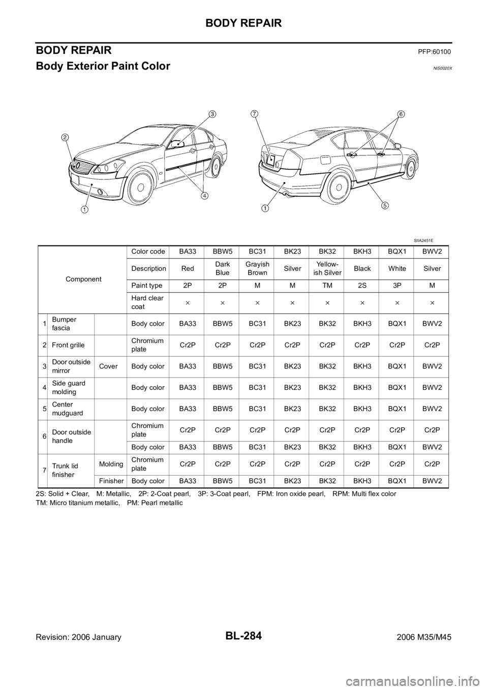
Body Exterior Paint ColorNIS0020X
2S: Solid + Clear, M: Metallic, 2P: 2-Coat pearl, 3P: 3-Coat pearl, FPM: Iron oxide pearl, RPM: Multi flex color
TM: Micro titanium metallic, PM: Pearl metallic ComponentColor code BA33 BBW5 BC31 BK23 BK32 BKH3 BQX1 BWV2
Description RedDark
BlueGrayish
BrownSilverYellow-
ish SilverBlack White Silver
Paint type 2P 2P M M TM 2S 3P M
Hard clear
coat
1Bumper
fasciaBody color BA33 BBW5 BC31 BK23 BK32 BKH3 BQX1 BWV2
2 Front grilleChromium
plateCr2P Cr2P Cr2P Cr2P Cr2P Cr2P Cr2P Cr2P
3Door outside
mirrorCover Body color BA33 BBW5 BC31 BK23 BK32 BKH3 BQX1 BWV2
4Side guard
moldingBody color BA33 BBW5 BC31 BK23 BK32 BKH3 BQX1 BWV2
5Center
mudguardBody color BA33 BBW5 BC31 BK23 BK32 BKH3 BQX1 BWV2
6Door outside
handleChromium
plateCr2P Cr2P Cr2P Cr2P Cr2P Cr2P Cr2P Cr2P
Body color BA33 BBW5 BC31 BK23 BK32 BKH3 BQX1 BWV2
7Trunk lid
finisherMoldingChromium
plateCr2P Cr2P Cr2P Cr2P Cr2P Cr2P Cr2P Cr2P
Finisher Body color BA33 BBW5 BC31 BK23 BK32 BKH3 BQX1 BWV2
SIIA2451E
Page 1224 of 5621
BODY REPAIR
BL-285
C
D
E
F
G
H
J
K
L
MA
B
BL
Revision: 2006 January2006 M35/M45
Body Component PartsNIS0020Y
UNDERBODY COMPONENT PARTS
SIIA2452E
Page 1225 of 5621

BL-286
BODY REPAIR
Revision: 2006 January2006 M35/M45
1. Front strut housing
2. Upper front hoodledge
3. Upper rear hoodledge
4. Hoodledge reinforcement
5. Upper dash assembly
6. Upper dash crossmember assembly
7. Harness clamp bracket
8. Cowl top
9. Lower center dash crossmember reinforcement
10. Lower dash crossmember reinforcement
11. Lower dash crossmember assembly (LH)
12. Lower dash crossmember (RH)
13. Front crossmember center
14. Steering column mounting reinforcement
15. Lower dash
16. Front floor center
17. Front floor
18. Inner sill
19. Rear seat crossmember reinforcement assembly
20. Front carpet bracket
21. Rear floor front
22. Rear floor seat belt anchor reinforcement
23. Rear seat reclining device bracket
24. Rear floor rear
25. Differential mounting bracket assembly
26. Rear floor side assembly
27. Rear bumper side stay
28. Front side member assembly
29. Front side member front extension
30. Front side member closing plate assembly
31. Front side member front closing plate
32. Front side member center closing plate
33. Front suspension mounting bracket
34. Front side member rear extension
35. Front side member rear reinforcement
36. Front side member outrigger assembly
37. Rear seat crossmember
38. 2ND rear crossmember
39. Rear crossmember
40. Rear side member assembly
41. Rear side member extension
Page 1226 of 5621
BODY REPAIR
BL-287
C
D
E
F
G
H
J
K
L
MA
B
BL
Revision: 2006 January2006 M35/M45
BODY COMPONENT PARTS
SIIA2453E
Page 1227 of 5621

BL-288
BODY REPAIR
Revision: 2006 January2006 M35/M45
1. Hood
2. Front fender (RH&LH)
3. Side body assembly (RH&LH)
4. Outer front pillar reinforcement (RH&LH)
5. Center pillar reinforcement (RH&LH)
6. Outer roof side rail reinforcement (RH&LH)
7. Outer sill reinforcement (RH&LH)
8. Inner roof side rail (RH&LH)
9. Inner center pillar (RH&LH)
10. Front roof rail brace (RH&LH)
11. Outer sill (RH&LH)
12. Inner rear pillar assembly (RH&LH)
13. Inner rear pillar rear (RH&LH)
14. Inner rear pillar reinforcement (RH&LH)
15. Outer rear wheelhouse (RH&LH)
16. Outer rear wheelhouse extension (RH&LH)
17. Inner rear wheelhouse (RH&LH)
18. Side parcel shelf assembly (RH&LH)
19. Seat back support (RH&LH)
20. Parcel shelf assembly
21. Rear waist
22. Roof assembly
23. Front roof rail
24. Front roof bow
25. Rear roof bow
26. Rear roof rail
27. Rear fender assembly (RH&LH)
28. Rear fender extension (RH&LH)
29. Rear bumper side bracket
30. Fuel filler lid (RH)
31. Rear panel assembly
32. Upper rear bumper retainer
33. Lower rear bumper retainer
34. Front door assembly (RH&LH)
35. Outer front door panel (RH&LH)
36. Rear door assembly (RH&LH)
37. Outer rear door panel (RH&LH)
38. Trunk lid
39. Front bumper reinforcement
40. Rear bumper stay
41. Rear bumper reinforcement
Page 1228 of 5621

BODY REPAIR
BL-289
C
D
E
F
G
H
J
K
L
MA
B
BL
Revision: 2006 January2006 M35/M45
Corrosion ProtectionNIS0020Z
DESCRIPTION
To provide improved corrosion prevention, the following anti-corrosive measures have been implemented in
NISSAN production plants. When repairing or replacing body panels, it is necessary to use the same anti-cor-
rosive measures.
Anti-corrosive Precoated Steel (Galvannealed Steel)
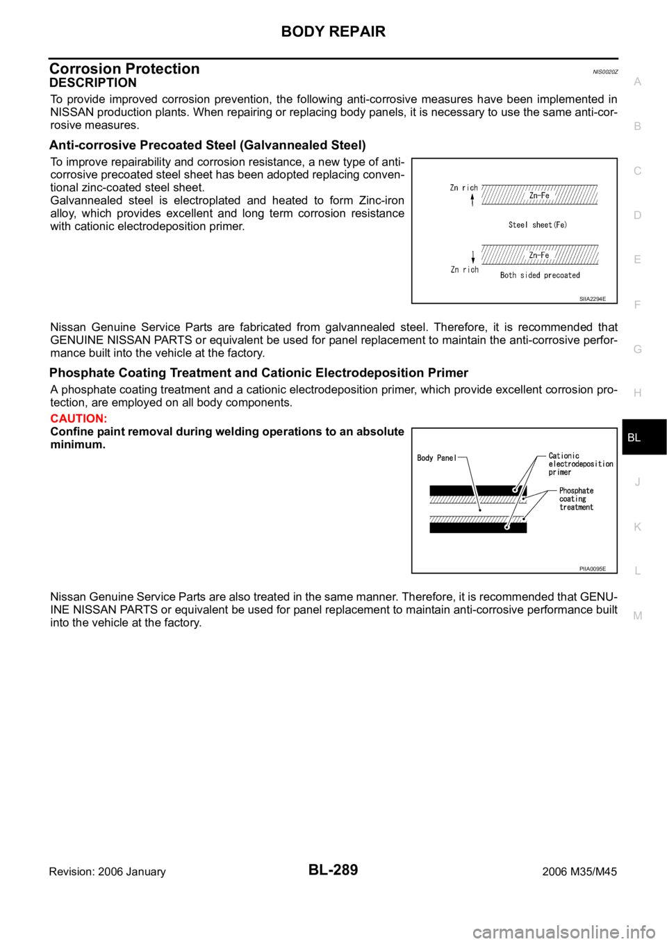
To improve repairability and corrosion resistance, a new type of anti-
corrosive precoated steel sheet has been adopted replacing conven-
tional zinc-coated steel sheet.
Galvannealed steel is electroplated and heated to form Zinc-iron
alloy, which provides excellent and long term corrosion resistance
with cationic electrodeposition primer.
Nissan Genuine Service Parts are fabricated from galvannealed steel. Therefore, it is recommended that
GENUINE NISSAN PARTS or equivalent be used for panel replacement to maintain the anti-corrosive perfor-
mance built into the vehicle at the factory.
Phosphate Coating Treatment and Cationic Electrodeposition Primer
A phosphate coating treatment and a cationic electrodeposition primer, which provide excellent corrosion pro-
tection, are employed on all body components.
CAUTION:
Confine paint removal during welding operations to an absolute
minimum.
Nissan Genuine Service Parts are also treated in the same manner. Therefore, it is recommended that GENU-
INE NISSAN PARTS or equivalent be used for panel replacement to maintain anti-corrosive performance built
into the vehicle at the factory.
SIIA2294E
PIIA0095E
Page 1229 of 5621
BL-290
BODY REPAIR
Revision: 2006 January2006 M35/M45
UNDERCOATING
The underside of the floor and wheelhouse are undercoated to prevent rust, vibration, noise and stone chip-
ping. Therefore, when such a panel is replaced or repaired, apply undercoating to that part. Use an undercoat-
ing which is rust preventive, soundproof, vibration-proof, shock-resistant, adhesive, and durable.
Precautions in Undercoating
1. Do not apply undercoating to any place unless specified (such as the areas above the muffler and three
way catalyst which are subjected to heat).
2. Do not undercoat the exhaust pipe or other parts which become hot.
3. Do not undercoat rotating parts.
4. Apply bitumen wax after applying undercoating.
5. After putting seal on the vehicle, put undercoating on it.
SIIA2454E