Page 1471 of 5621
DI-38
UNIFIED METER AND A/C AMP
Revision: 2006 January2006 M35/M45
5. CHECK COMMUNICATION SIGNAL (TX: UNIFIED METER AND A/C AMP.)
1. Turn ignition switch OFF.
2. Connect unified meter and A/C amp. connector.
3. Turn ignition switch ON.
4. Check voltage signal between combination meter harness con-
nector and ground.
OK or NG
OK >> GO TO 6.
NG >> Replace unified meter and A/C amp.
6. CHECK UNIFIED METER AND A/C AMP OUTPUT VOLTAGE (RX: UNIFIED METER AND A/C AMP.)
1. Turn ignition switch OFF.
2. Disconnect combination meter connector.
3. Turn ignition switch ON.
4. Check voltage between unified meter and A/C amp. harness
connector and ground.
OK or NG
OK >> GO TO 7.
NG >> Replace unified meter and A/C amp.
Terminals
Voltage (Approx.) (+)
(–)
Combination meter
connectorTerminal
M52 15 Ground
PKIB7650E
SKIA3362E
Terminals
Voltage (Approx.) (+)
(–)
Unified meter and A/C
amp. connectorTerminal
M64 27 Ground 5 V
PKIB7651E
Page 1472 of 5621
UNIFIED METER AND A/C AMP
DI-39
C
D
E
F
G
H
I
J
L
MA
B
DI
Revision: 2006 January2006 M35/M45
7. CHECK COMMUNICATION SIGNAL (RX: UNIFIED METER AND A/C AMP.)
1. Turn ignition switch OFF.
2. Connect combination meter connector.
3. Turn ignition switch ON.
4. Check voltage signal between unified meter and A/C amp. har-
ness connector and ground.
OK or NG
OK >> Replace unified meter and A/C amp.
NG >> Replace combination meter.
DTC [B2205] Vehicle Speed CircuitNKS003UM
Symptom: Displays “VEHICLE SPEED CIRC [B2205]” as a self-diagnosis results of unified meter and A/C
amp.
Preform self-diagnosis of ABS actuator and electric unit (control unit), and repair or replace malfunctioning
parts. Refer to BRC-22, "
CONSULT-II Functions (ABS)" .
Removal and Installation of Unified Meter and A/C Amp. NKS003UN
REMOVAL
1. Remove the audio unit. Refer to AV- 1 3 0 , "Audio Unit" (Without
mobile entertainment system) or AV- 2 8 5 , "
Audio Unit" . (With
mobile entertainment system).
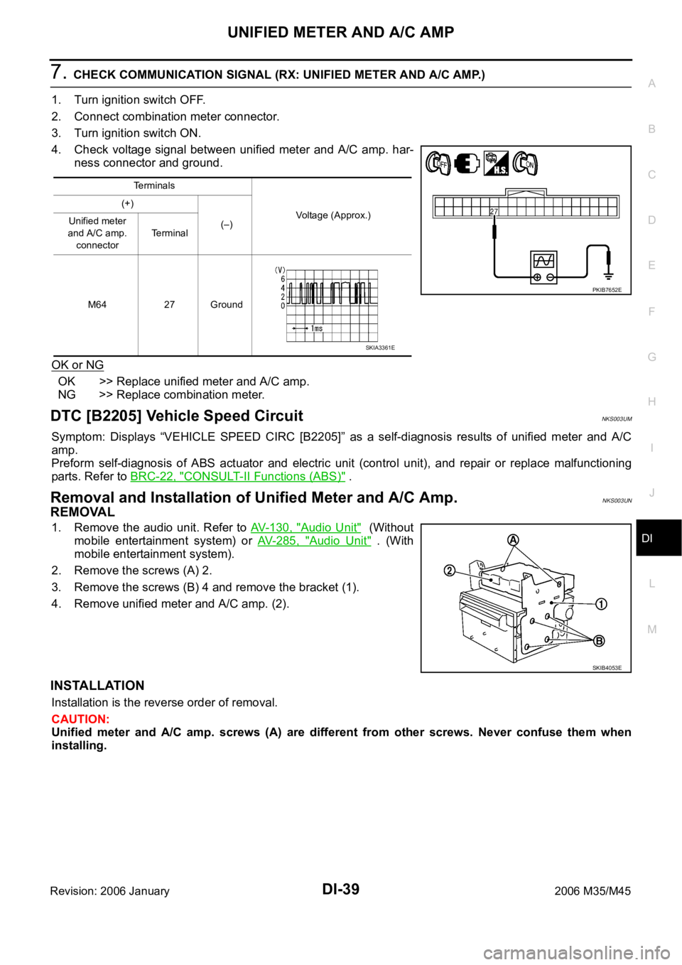
2. Remove the screws (A) 2.
3. Remove the screws (B) 4 and remove the bracket (1).
4. Remove unified meter and A/C amp. (2).
INSTALLATION
Installation is the reverse order of removal.
CAUTION:
Unified meter and A/C amp. screws (A) are different from other screws. Never confuse them when
installing.
Terminals
Voltage (Approx.) (+)
(–) Unified meter
and A/C amp.
connectorTerminal
M64 27 Ground
PKIB7652E
SKIA3361E
SKIB4053E
Page 1487 of 5621
DI-54
WARNING LAMPS
Revision: 2006 January2006 M35/M45
6. CHECK BCM INPUT SIGNAL
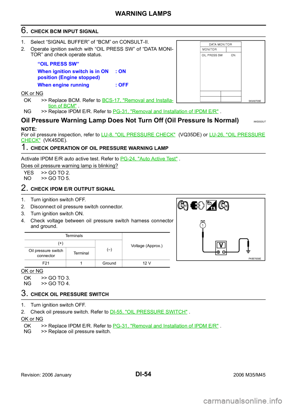
1. Select “SIGNAL BUFFER” of “BCM” on CONSULT-II.
2. Operate ignition switch with “OIL PRESS SW” of “DATA MONI-
TOR” and check operate status.
OK or NG
OK >> Replace BCM. Refer to BCS-17, "Removal and Installa-
tion of BCM" .
NG >> Replace IPDM E/R. Refer to PG-31, "
Removal and Installation of IPDM E/R" .
Oil Pressure Warning Lamp Does Not Turn Off (Oil Pressure Is Normal)NKS003UT
NOTE:
For oil pressure inspection, refer to LU-8, "
OIL PRESSURE CHECK" (VQ35DE) or LU-26, "OIL PRESSURE
CHECK" (VK45DE).
1. CHECK OPERATION OF OIL PRESSURE WARNING LAMP
Activate IPDM E/R auto active test. Refer to PG-24, "
Auto Active Test" .
Does oil pressure warning lamp is blinking?
YES >> GO TO 2.
NO >> GO TO 5.
2. CHECK IPDM E/R OUTPUT SIGNAL
1. Turn ignition switch OFF.
2. Disconnect oil pressure switch connector.
3. Turn ignition switch ON.
4. Check voltage between oil pressure switch harness connector
and ground.
OK or NG
OK >> GO TO 3.
NG >> GO TO 4.
3. CHECK OIL PRESSURE SWITCH
1. Turn ignition switch OFF.
2. Check oil pressure switch. Refer to DI-55, "
OIL PRESSURE SWITCH" .
OK or NG
OK >> Replace IPDM E/R. Refer to PG-31, "Removal and Installation of IPDM E/R" .
NG >> Replace oil pressure switch.“OIL PRESS SW”
When ignition switch is in ON
position (Engine stopped): ON
When engine running : OFF
SKIA8709E
Terminals
Voltage (Approx.) (+)
(–)
Oil pressure switch
connectorTe r m i n a l
F21 1 Ground 12 V
PKIB7658E
Page 1488 of 5621
WARNING LAMPS
DI-55
C
D
E
F
G
H
I
J
L
MA
B
DI
Revision: 2006 January2006 M35/M45
4. CHECK OIL PRESSURE SWITCH CIRCUIT
1. Turn ignition switch OFF.
2. Disconnect IPDM E/R connector.
3. Check continuity between IPDM E/R harness connector and
ground.
OK or NG
OK >> Replace IPDM E/R. Refer to PG-31, "Removal and
Installation of IPDM E/R" .
NG >> Repair harness or connector.
5. CHECK IPDM E/R (CONSULT-II)
Perform self-diagnosis of IPDM E/R. Refer to PG-20, "
CONSULT-II Function (IPDM E/R)" .
Self
-diagnostic results content
No malfunction detected>> Replace combination meter.
Malfunction detected>> Check applicable parts, and repair or replace corresponding parts.
Electrical Component InspectionNKS003UU
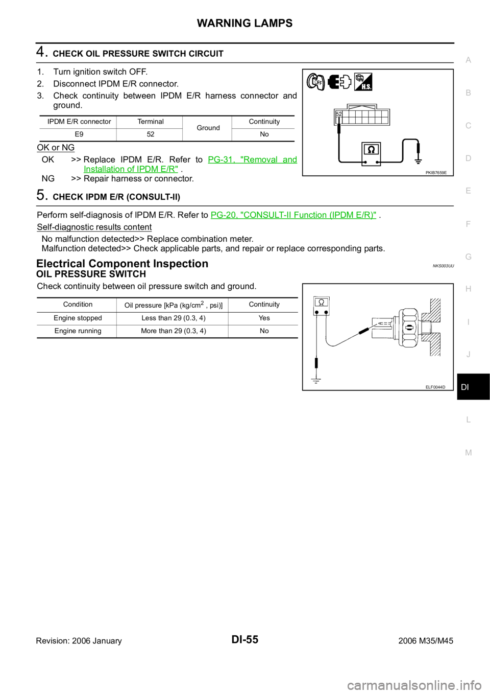
OIL PRESSURE SWITCH
Check continuity between oil pressure switch and ground.
IPDM E/R connector Terminal
GroundContinuity
E9 52 No
PKIB7659E
Condition
Oil pressure [kPa (kg/cm2 , psi)]Continuity
Engine stopped Less than 29 (0.3, 4) Yes
Engine running More than 29 (0.3, 4) No
ELF0044D
Page 1493 of 5621
DI-60
WARNING CHIME
Revision: 2006 January2006 M35/M45
WARNING CHIMEPFP:24814
System DescriptionNKS003UY
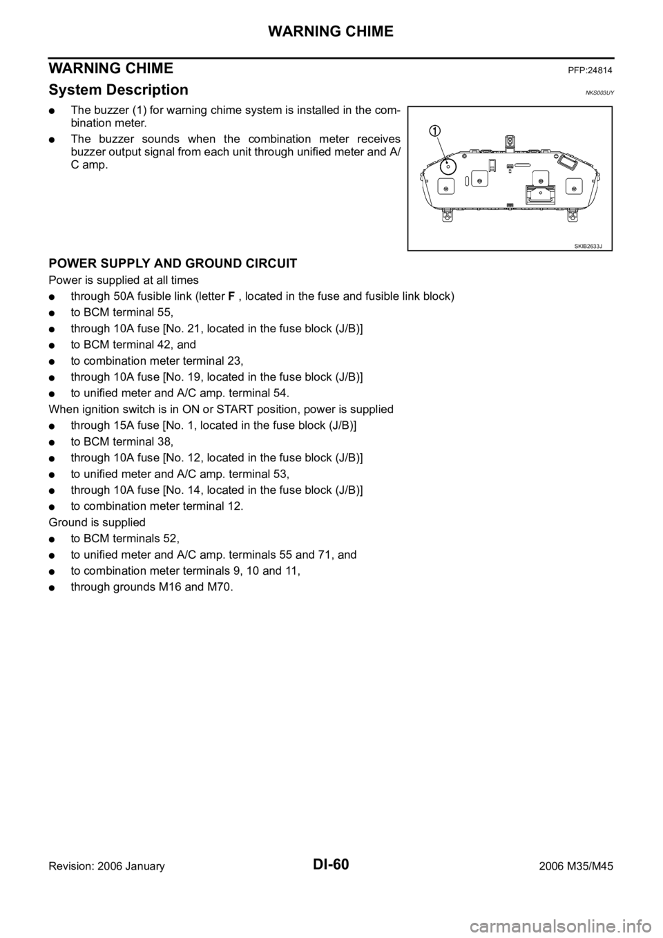
The buzzer (1) for warning chime system is installed in the com-
bination meter.
The buzzer sounds when the combination meter receives
buzzer output signal from each unit through unified meter and A/
C amp.
POWER SUPPLY AND GROUND CIRCUIT
Power is supplied at all times
through 50A fusible link (letter F , located in the fuse and fusible link block)
to BCM terminal 55,
through 10A fuse [No. 21, located in the fuse block (J/B)]
to BCM terminal 42, and
to combination meter terminal 23,
through 10A fuse [No. 19, located in the fuse block (J/B)]
to unified meter and A/C amp. terminal 54.
When ignition switch is in ON or START position, power is supplied
through 15A fuse [No. 1, located in the fuse block (J/B)]
to BCM terminal 38,
through 10A fuse [No. 12, located in the fuse block (J/B)]
to unified meter and A/C amp. terminal 53,
through 10A fuse [No. 14, located in the fuse block (J/B)]
to combination meter terminal 12.
Ground is supplied
to BCM terminals 52,
to unified meter and A/C amp. terminals 55 and 71, and
to combination meter terminals 9, 10 and 11,
through grounds M16 and M70.
SKIB2633J
Page 1500 of 5621
WARNING CHIME
DI-67
C
D
E
F
G
H
I
J
L
MA
B
DI
Revision: 2006 January2006 M35/M45
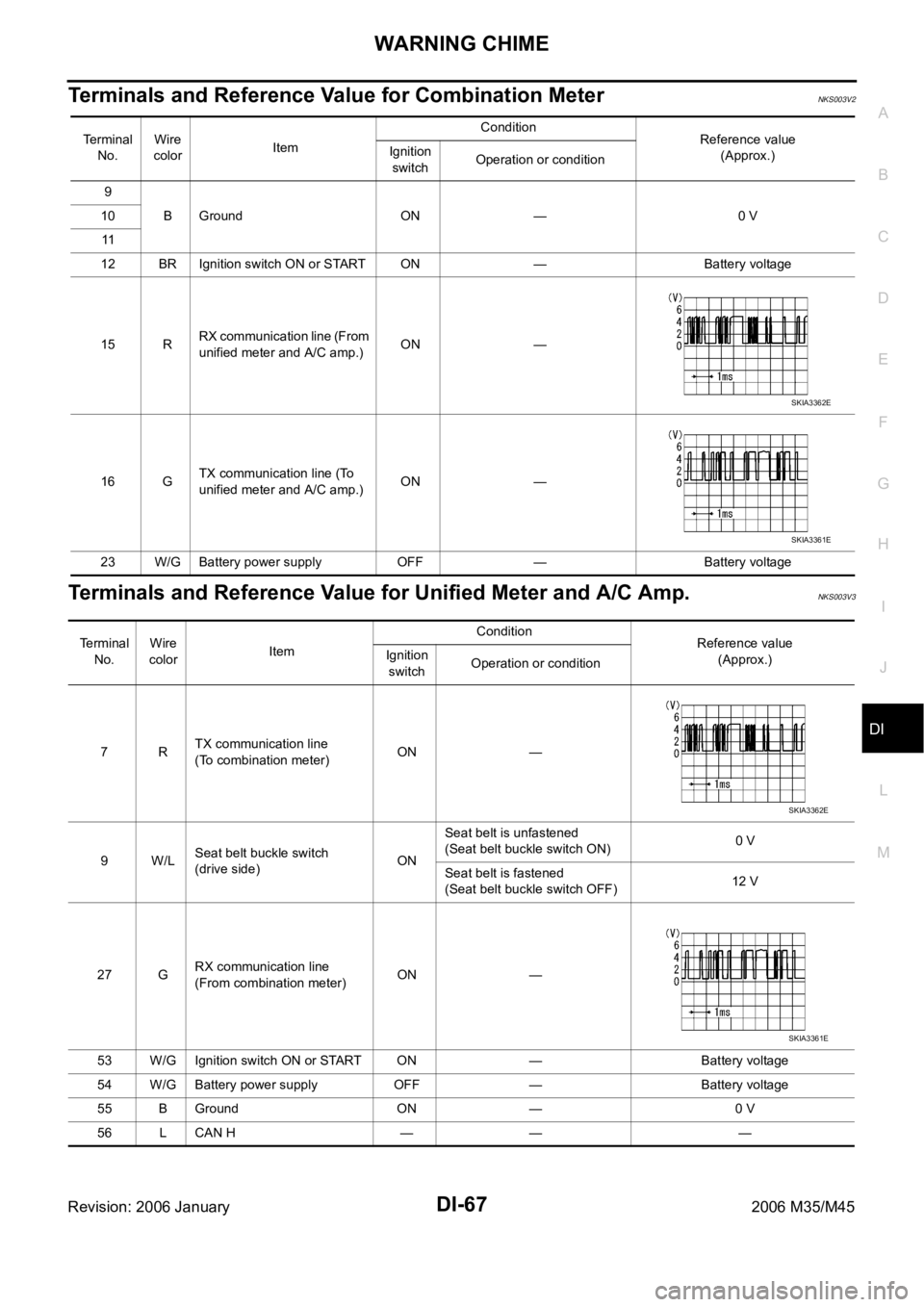
Terminals and Reference Value for Combination MeterNKS003V2
Terminals and Reference Value for Unified Meter and A/C Amp.NKS003V3
Te r m i n a l
No.Wire
colorItemCondition
Reference value
(Approx.) Ignition
switchOperation or condition
9
B Ground ON — 0 V 10
11
12 BR Ignition switch ON or START ON — Battery voltage
15 RRX communication line (From
unified meter and A/C amp.)ON —
16 GTX communication line (To
unified meter and A/C amp.)ON —
23 W/G Battery power supply OFF — Battery voltage
SKIA3362E
SKIA3361E
Terminal
No.Wire
colorItemCondition
Reference value
(Approx.) Ignition
switchOperation or condition
7RTX communication line
(To combination meter)ON —
9W/LSeat belt buckle switch
(drive side)ONSeat belt is unfastened
(Seat belt buckle switch ON)0 V
Seat belt is fastened
(Seat belt buckle switch OFF)12 V
27 GRX communication line
(From combination meter)ON —
53 W/G Ignition switch ON or START ON — Battery voltage
54 W/G Battery power supply OFF — Battery voltage
55 B Ground ON — 0 V
56 L CAN H — — —
SKIA3362E
SKIA3361E
Page 1501 of 5621
DI-68
WARNING CHIME
Revision: 2006 January2006 M35/M45
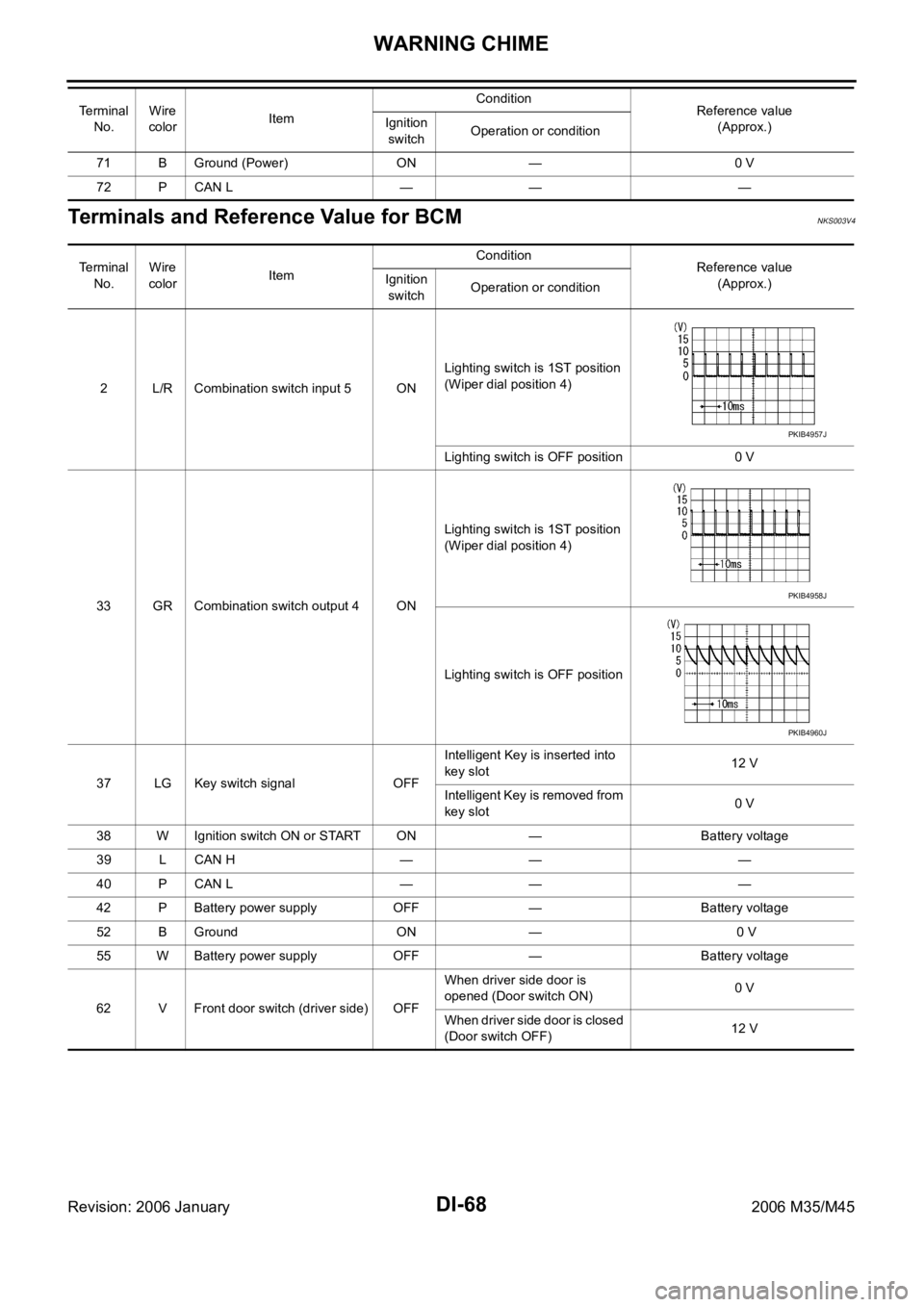
Terminals and Reference Value for BCMNKS003V4
71 B Ground (Power) ON — 0 V
72 P CAN L — — — Te r m i n a l
No.Wire
colorItemCondition
Reference value
(Approx.) Ignition
switchOperation or condition
Te r m i n a l
No.Wire
colorItemCondition
Reference value
(Approx.) Ignition
switchOperation or condition
2 L/R Combination switch input 5 ONLighting switch is 1ST position
(Wiper dial position 4)
Lighting switch is OFF position 0 V
33 GR Combination switch output 4 ONLighting switch is 1ST position
(Wiper dial position 4)
Lighting switch is OFF position
37 LG Key switch signal OFFIntelligent Key is inserted into
key slot12 V
Intelligent Key is removed from
key slot0 V
38 W Ignition switch ON or START ON — Battery voltage
39 L CAN H — — —
40 P CAN L — — —
42 P Battery power supply OFF — Battery voltage
52 B Ground ON — 0 V
55 W Battery power supply OFF — Battery voltage
62 V Front door switch (driver side) OFFWhen driver side door is
opened (Door switch ON)0 V
When driver side door is closed
(Door switch OFF)12 V
PKIB4957J
PKIB4958J
PKIB4960J
Page 1505 of 5621
DI-72
WARNING CHIME
Revision: 2006 January2006 M35/M45
2. CHECK UNIFIED METER AND A/C AMP. (CONSULT-II)
Perform self-diagnosis of unified meter and A/C amp. Refer to DI-71, "
CONSULT-II Function (METER A/C
AMP)" .
Self
-diagnostic results content
No malfunction detected>> INSPECTION END
Malfunction detected>> Check applicable parts, and repair or replace corresponding parts.
SYMPTOM CHART
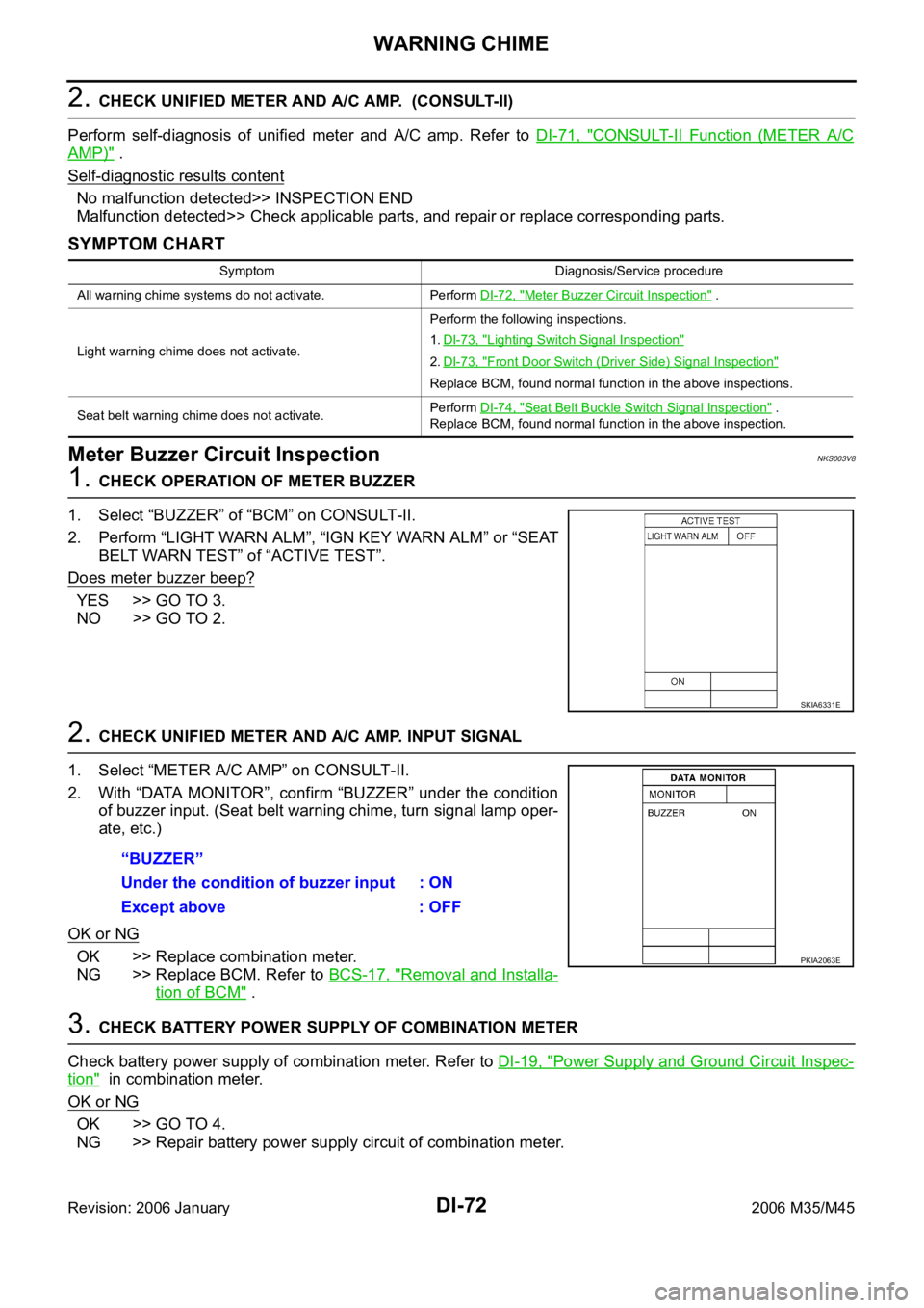
Meter Buzzer Circuit InspectionNKS003V8
1. CHECK OPERATION OF METER BUZZER
1. Select “BUZZER” of “BCM” on CONSULT-II.
2. Perform “LIGHT WARN ALM”, “IGN KEY WARN ALM” or “SEAT
BELT WARN TEST” of “ACTIVE TEST”.
Does meter buzzer beep?
YES >> GO TO 3.
NO >> GO TO 2.
2. CHECK UNIFIED METER AND A/C AMP. INPUT SIGNAL
1. Select “METER A/C AMP” on CONSULT-II.
2. With “DATA MONITOR”, confirm “BUZZER” under the condition
of buzzer input. (Seat belt warning chime, turn signal lamp oper-
ate, etc.)
OK or NG
OK >> Replace combination meter.
NG >> Replace BCM. Refer to BCS-17, "
Removal and Installa-
tion of BCM" .
3. CHECK BATTERY POWER SUPPLY OF COMBINATION METER
Check battery power supply of combination meter. Refer to DI-19, "
Power Supply and Ground Circuit Inspec-
tion" in combination meter.
OK or NG
OK >> GO TO 4.
NG >> Repair battery power supply circuit of combination meter.
Symptom Diagnosis/Service procedure
All warning chime systems do not activate. Perform DI-72, "
Meter Buzzer Circuit Inspection" .
Light warning chime does not activate.Perform the following inspections.
1.DI-73, "
Lighting Switch Signal Inspection"
2.DI-73, "Front Door Switch (Driver Side) Signal Inspection"
Replace BCM, found normal function in the above inspections.
Seat belt warning chime does not activate.Perform DI-74, "
Seat Belt Buckle Switch Signal Inspection" .
Replace BCM, found normal function in the above inspection.
SKIA6331E
“BUZZER”
Under the condition of buzzer input : ON
Except above : OFF
PKIA2063E