2006 INFINITI M35 ground
[x] Cancel search: groundPage 1530 of 5621
LANE DEPARTURE WARNING SYSTEM
DI-97
C
D
E
F
G
H
I
J
L
MA
B
DI
Revision: 2006 January2006 M35/M45
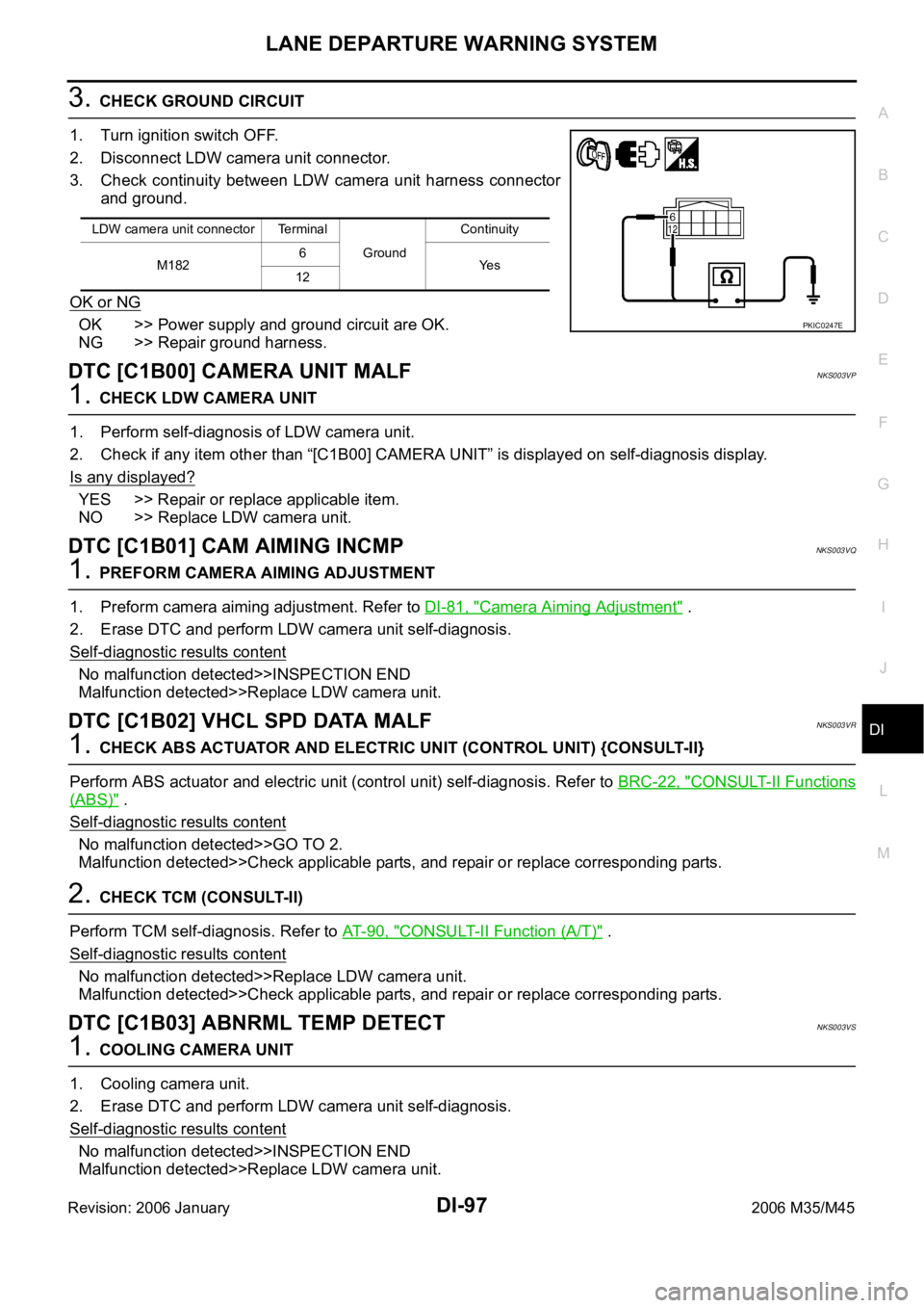
3. CHECK GROUND CIRCUIT
1. Turn ignition switch OFF.
2. Disconnect LDW camera unit connector.
3. Check continuity between LDW camera unit harness connector
and ground.
OK or NG
OK >> Power supply and ground circuit are OK.
NG >> Repair ground harness.
DTC [C1B00] CAMERA UNIT MALFNKS003VP
1. CHECK LDW CAMERA UNIT
1. Perform self-diagnosis of LDW camera unit.
2. Check if any item other than “[C1B00] CAMERA UNIT” is displayed on self-diagnosis display.
Is any displayed?
YES >> Repair or replace applicable item.
NO >> Replace LDW camera unit.
DTC [C1B01] CAM AIMING INCMPNKS003VQ
1. PREFORM CAMERA AIMING ADJUSTMENT
1. Preform camera aiming adjustment. Refer to DI-81, "
Camera Aiming Adjustment" .
2. Erase DTC and perform LDW camera unit self-diagnosis.
Self
-diagnostic results content
No malfunction detected>>INSPECTION END
Malfunction detected>>Replace LDW camera unit.
DTC [C1B02] VHCL SPD DATA MALFNKS003VR
1. CHECK ABS ACTUATOR AND ELECTRIC UNIT (CONTROL UNIT) {CONSULT-II}
Perform ABS actuator and electric unit (control unit) self-diagnosis. Refer to BRC-22, "
CONSULT-II Functions
(ABS)" .
Self
-diagnostic results content
No malfunction detected>>GO TO 2.
Malfunction detected>>Check applicable parts, and repair or replace corresponding parts.
2. CHECK TCM (CONSULT-II)
Perform TCM self-diagnosis. Refer to AT- 9 0 , "
CONSULT-II Function (A/T)" .
Self
-diagnostic results content
No malfunction detected>>Replace LDW camera unit.
Malfunction detected>>Check applicable parts, and repair or replace corresponding parts.
DTC [C1B03] ABNRML TEMP DETECTNKS003VS
1. COOLING CAMERA UNIT
1. Cooling camera unit.
2. Erase DTC and perform LDW camera unit self-diagnosis.
Self
-diagnostic results content
No malfunction detected>>INSPECTION END
Malfunction detected>>Replace LDW camera unit.
LDW camera unit connector Terminal
GroundContinuity
M1826
Ye s
12
PKIC0247E
Page 1531 of 5621
![INFINITI M35 2006 Factory Service Manual DI-98
LANE DEPARTURE WARNING SYSTEM
Revision: 2006 January2006 M35/M45
DTC [U1000] CAN COMM CIRCUITNKS003VT
1. CHECK CAN COMMUNICATION
1. Select “SELF-DIAG RESULTS” mode for “LDW” with CONS INFINITI M35 2006 Factory Service Manual DI-98
LANE DEPARTURE WARNING SYSTEM
Revision: 2006 January2006 M35/M45
DTC [U1000] CAN COMM CIRCUITNKS003VT
1. CHECK CAN COMMUNICATION
1. Select “SELF-DIAG RESULTS” mode for “LDW” with CONS](/manual-img/42/57023/w960_57023-1530.png)
DI-98
LANE DEPARTURE WARNING SYSTEM
Revision: 2006 January2006 M35/M45
DTC [U1000] CAN COMM CIRCUITNKS003VT
1. CHECK CAN COMMUNICATION
1. Select “SELF-DIAG RESULTS” mode for “LDW” with CONSULT-II.
2. Print out CONSULT-II screen.
>> Go to “LAN SYSTEM”. Refer to LAN-7, "
Precautions When Using CONSULT-II" .
DTC [U1010] CONTROL UNIT (CAN)NKS003VU
Replace LDW camera unit, when “[U1010] CONTROL UNIT (CAN)” is displayed on self-diagnosis display.
LDW Chime Circuit InspectionNKS003VV
1. CHECK OPERATION OF LDW CHIME
Check LDW chime operation “BUZZER DRIVE” in “ACTIVE TEST”
mode with CONSULT-II.
OK or NG
OK >> LDW chime is OK. Return to DI-96, "SYMPTOM
CHART" .
NG >> GO TO 2.
2. CHECK LDW CHIME POWER SUPPLY CIRCUIT
1. Turn ignition switch OFF.
2. Disconnect LDW chime connector.
3. Turn ignition switch ON.
4. Check voltage between LDW chime harness connector and
ground.
OK or NG
OK >> GO TO 3.
NG >> Check harness between fuse and LDW chime.
3. CHECK LDW CHIME GROUND CIRCUIT
1. Turn ignition switch OFF.
2. Check continuity between LDW chime harness connector and
ground.
OK or NG
OK >> GO TO 4.
NG >> Repair harness or connector.“BUZZER DRIVE”
Touch “ON” : LDW chime is activated.
Touch “OFF” : LDW chime is not activated.
SKIB1787E
Terminals
Voltage (Approx.) (+)
(–)
LDW chime connector Terminal
M58 1 Ground Battery voltage
PKIC0248E
LDW chime connector Terminal
GroundContinuity
M58 3 Yes
PKIC0249E
Page 1532 of 5621
LANE DEPARTURE WARNING SYSTEM
DI-99
C
D
E
F
G
H
I
J
L
MA
B
DI
Revision: 2006 January2006 M35/M45
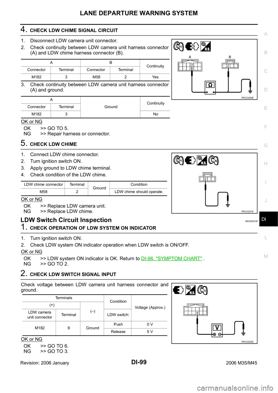
4. CHECK LDW CHIME SIGNAL CIRCUIT
1. Disconnect LDW camera unit connector.
2. Check continuity between LDW camera unit harness connector
(A) and LDW chime harness connector (B).
3. Check continuity between LDW camera unit harness connector
(A) and ground.
OK or NG
OK >> GO TO 5.
NG >> Repair harness or connector.
5. CHECK LDW CHIME
1. Connect LDW chime connector.
2. Turn ignition switch ON.
3. Apply ground to LDW chime terminal.
4. Check condition of the LDW chime.
OK or NG
OK >> Replace LDW camera unit.
NG >> Replace LDW chime.
LDW Switch Circuit InspectionNKS003VW
1. CHECK OPERATION OF LDW SYSTEM ON INDICATOR
1. Turn ignition switch ON.
2. Check LDW system ON indicator operation when LDW switch is ON/OFF.
OK or NG
OK >> LDW system ON indicator is OK. Return to DI-96, "SYMPTOM CHART" .
NG >> GO TO 2.
2. CHECK LDW SWITCH SIGNAL INPUT
Check voltage between LDW camera unit harness connector and
ground.
OK or NG
OK >> GO TO 6.
NG >> GO TO 3.
AB
Continuity
Connector Terminal Connector Terminal
M182 3 M58 2 Yes
A
GroundContinuity
Connector Terminal
M182 3 No
PKIC0250E
LDW chime connector Terminal
GroundCondition
M58 2 LDW chime should operate.
PKIC0251E
Terminals
Condition
Voltage (Approx.) (+)
(–)
LDW camera
unit connectorTerminal LDW switch:
M182 9 GroundPush 0 V
Release 5 V
PKIC0252E
Page 1533 of 5621
DI-100
LANE DEPARTURE WARNING SYSTEM
Revision: 2006 January2006 M35/M45
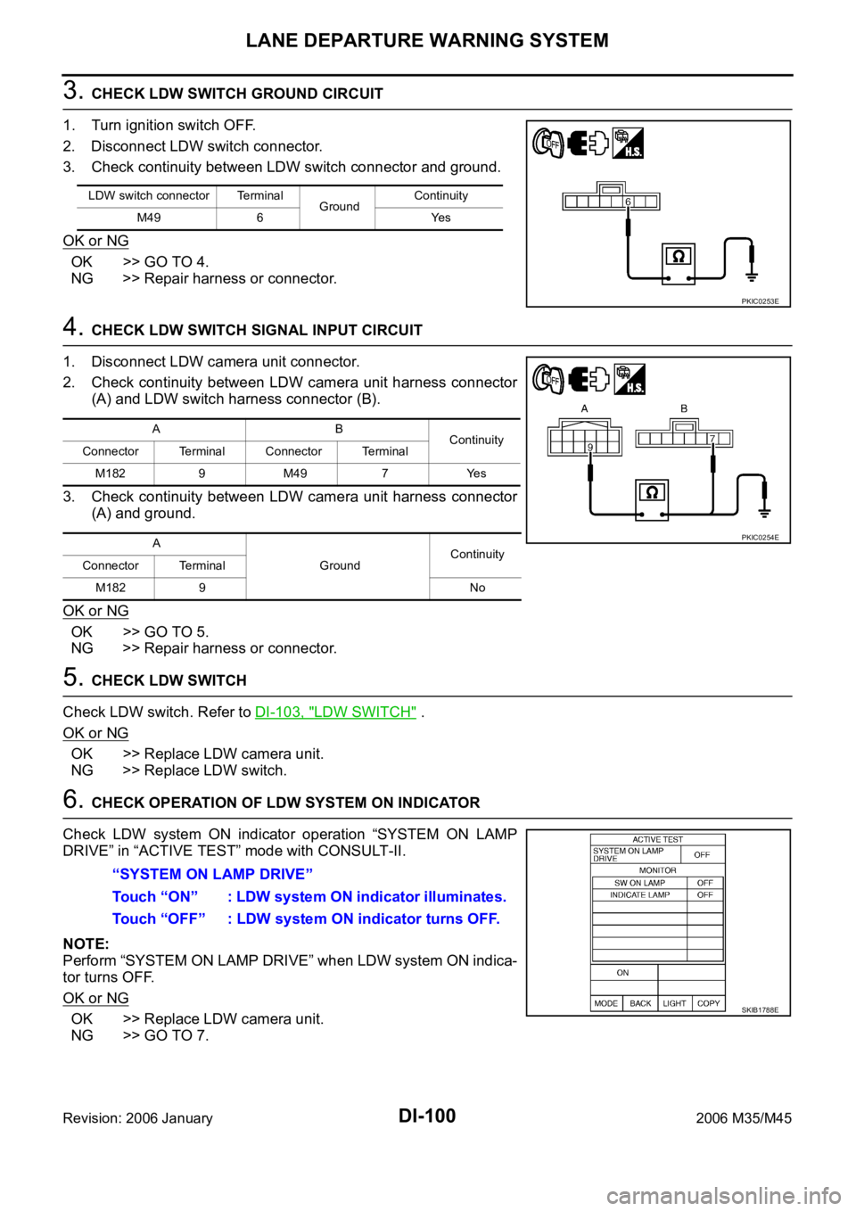
3. CHECK LDW SWITCH GROUND CIRCUIT
1. Turn ignition switch OFF.
2. Disconnect LDW switch connector.
3. Check continuity between LDW switch connector and ground.
OK or NG
OK >> GO TO 4.
NG >> Repair harness or connector.
4. CHECK LDW SWITCH SIGNAL INPUT CIRCUIT
1. Disconnect LDW camera unit connector.
2. Check continuity between LDW camera unit harness connector
(A) and LDW switch harness connector (B).
3. Check continuity between LDW camera unit harness connector
(A) and ground.
OK or NG
OK >> GO TO 5.
NG >> Repair harness or connector.
5. CHECK LDW SWITCH
Check LDW switch. Refer to DI-103, "
LDW SWITCH" .
OK or NG
OK >> Replace LDW camera unit.
NG >> Replace LDW switch.
6. CHECK OPERATION OF LDW SYSTEM ON INDICATOR
Check LDW system ON indicator operation “SYSTEM ON LAMP
DRIVE” in “ACTIVE TEST” mode with CONSULT-II.
NOTE:
Perform “SYSTEM ON LAMP DRIVE” when LDW system ON indica-
tor turns OFF.
OK or NG
OK >> Replace LDW camera unit.
NG >> GO TO 7.
LDW switch connector Terminal
GroundContinuity
M49 6 Yes
PKIC0253E
AB
Continuity
Connector Terminal Connector Terminal
M1829 M497 Yes
A
GroundContinuity
Connector Terminal
M182 9 No
PKIC0254E
“SYSTEM ON LAMP DRIVE”
Touch “ON” : LDW system ON indicator illuminates.
Touch “OFF” : LDW system ON indicator turns OFF.
SKIB1788E
Page 1534 of 5621
LANE DEPARTURE WARNING SYSTEM
DI-101
C
D
E
F
G
H
I
J
L
MA
B
DI
Revision: 2006 January2006 M35/M45
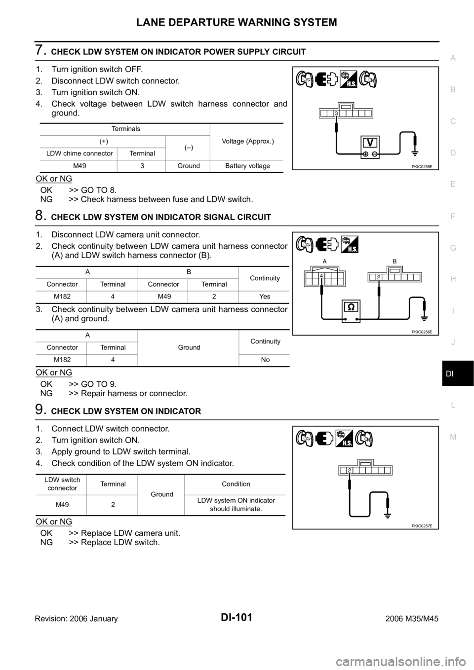
7. CHECK LDW SYSTEM ON INDICATOR POWER SUPPLY CIRCUIT
1. Turn ignition switch OFF.
2. Disconnect LDW switch connector.
3. Turn ignition switch ON.
4. Check voltage between LDW switch harness connector and
ground.
OK or NG
OK >> GO TO 8.
NG >> Check harness between fuse and LDW switch.
8. CHECK LDW SYSTEM ON INDICATOR SIGNAL CIRCUIT
1. Disconnect LDW camera unit connector.
2. Check continuity between LDW camera unit harness connector
(A) and LDW switch harness connector (B).
3. Check continuity between LDW camera unit harness connector
(A) and ground.
OK or NG
OK >> GO TO 9.
NG >> Repair harness or connector.
9. CHECK LDW SYSTEM ON INDICATOR
1. Connect LDW switch connector.
2. Turn ignition switch ON.
3. Apply ground to LDW switch terminal.
4. Check condition of the LDW system ON indicator.
OK or NG
OK >> Replace LDW camera unit.
NG >> Replace LDW switch.
Te r m i n a l s
Voltage (Approx.) (+)
(–)
LDW chime connector Terminal
M49 3 Ground Battery voltage
PKIC0255E
AB
Continuity
Connector Terminal Connector Terminal
M1824 M492 Yes
A
GroundContinuity
Connector Terminal
M182 4 No
PKIC0256E
LDW switch
connectorTerminal
GroundCondition
M49 2 LDW system ON indicator
should illuminate.
PKIC0257E
Page 1535 of 5621
DI-102
LANE DEPARTURE WARNING SYSTEM
Revision: 2006 January2006 M35/M45
LDW Indicator Lamp Circuit InspectionNKS003VX
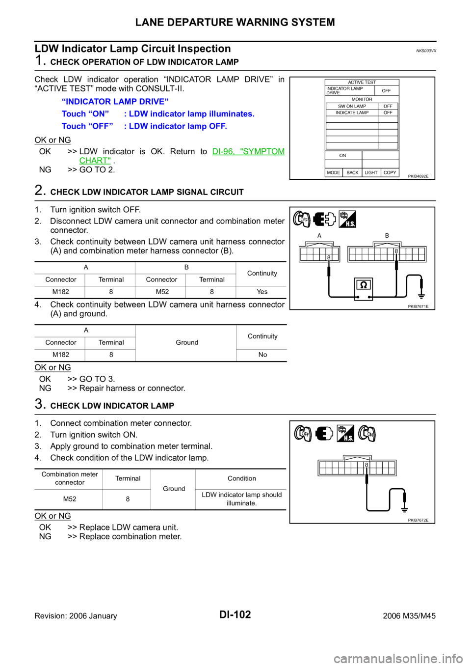
1. CHECK OPERATION OF LDW INDICATOR LAMP
Check LDW indicator operation “INDICATOR LAMP DRIVE” in
“ACTIVE TEST” mode with CONSULT-II.
OK or NG
OK >> LDW indicator is OK. Return to DI-96, "SYMPTOM
CHART" .
NG >> GO TO 2.
2. CHECK LDW INDICATOR LAMP SIGNAL CIRCUIT
1. Turn ignition switch OFF.
2. Disconnect LDW camera unit connector and combination meter
connector.
3. Check continuity between LDW camera unit harness connector
(A) and combination meter harness connector (B).
4. Check continuity between LDW camera unit harness connector
(A) and ground.
OK or NG
OK >> GO TO 3.
NG >> Repair harness or connector.
3. CHECK LDW INDICATOR LAMP
1. Connect combination meter connector.
2. Turn ignition switch ON.
3. Apply ground to combination meter terminal.
4. Check condition of the LDW indicator lamp.
OK or NG
OK >> Replace LDW camera unit.
NG >> Replace combination meter.“INDICATOR LAMP DRIVE”
Touch “ON” : LDW indicator lamp illuminates.
Touch “OFF” : LDW indicator lamp OFF.
PKIB4692E
AB
Continuity
Connector Terminal Connector Terminal
M182 8 M52 8 Yes
A
GroundContinuity
Connector Terminal
M182 8 No
PKIB7671E
Combination meter
connectorTe r m i n a l
GroundCondition
M52 8LDW indicator lamp should
illuminate.
PKIB7672E
Page 1545 of 5621

EC-2Revision: 2006 January2006 M35/M45 Inspection Procedure ...........................................
.155
Diagnostic Procedure ...........................................156
TROUBLE DIAGNOSIS FOR INTERMITTENT INCI-
DENT .......................................................................165
Description ............................................................165
Diagnostic Procedure ...........................................165
POWER SUPPLY AND GROUND CIRCUIT ...........166
Wiring Diagram .....................................................166
Diagnostic Procedure ...........................................167
Ground Inspection ................................................172
DTC U1000, U1001 CAN COMMUNICATION LINE .173
Description ............................................................173
On Board Diagnosis Logic ....................................173
DTC Confirmation Procedure ...............................173
Wiring Diagram .....................................................174
Diagnostic Procedure ...........................................175
DTC U1010 CAN COMMUNICATION .....................176
Description ............................................................176
On Board Diagnosis Logic ....................................176
DTC Confirmation Procedure ...............................176
Diagnostic Procedure ...........................................177
DTC P0011, P0021 IVT CONTROL ........................178
Description ............................................................178
CONSULT-II Reference Value in Data Monitor Mode
.178
On Board Diagnosis Logic ....................................179
DTC Confirmation Procedure ...............................179
Diagnostic Procedure ...........................................180
Component Inspection ..........................................181
Removal and Installation ......................................181
DTC P0031, P0032, P0051, P0052 A/F SENSOR 1
HEATER ..................................................................182
Description ............................................................182
CONSULT-II Reference Value in Data Monitor Mode
.182
On Board Diagnosis Logic ....................................182
DTC Confirmation Procedure ...............................182
Wiring Diagram .....................................................183
Diagnostic Procedure ...........................................186
Component Inspection ..........................................188
Removal and Installation ......................................188
DTC P0037, P0038, P0057, P0058 HO2S2 HEATER .189
Description ............................................................189
CONSULT-II Reference Value in Data Monitor Mode
.189
On Board Diagnosis Logic ....................................189
DTC Confirmation Procedure ...............................190
Wiring Diagram ....................................................
.191
Diagnostic Procedure ...........................................194
Component Inspection ..........................................196
Removal and Installation ......................................196
DTC P0075, P0081 IVT CONTROL SOLENOID
VALVE .....................................................................197
Component Description ........................................197
CONSULT-II Reference Value in Data Monitor Mode
.197
On Board Diagnosis Logic ....................................197
DTC Confirmation Procedure ...............................197
Wiring Diagram .....................................................198Diagnostic Procedure ............................................202
Component Inspection ..........................................204
Removal and Installation .......................................204
DTC P0101 MAF SENSOR .....................................205
Component Description ........................................205
CONSULT-II Reference Value in Data Monitor Mode
.205
On Board Diagnosis Logic ....................................205
DTC Confirmation Procedure ................................206
Overall Function Check .........................................207
Wiring Diagram .....................................................208
Diagnostic Procedure ............................................209
Component Inspection ..........................................212
Removal and Installation .......................................213
DTC P0102, P0103 MAF SENSOR .........................214
Component Description ........................................214
CONSULT-II Reference Value in Data Monitor Mode
.214
On Board Diagnosis Logic ....................................214
DTC Confirmation Procedure ................................215
Wiring Diagram .....................................................216
Diagnostic Procedure ............................................217
Component Inspection ..........................................219
Removal and Installation .......................................220
DTC P0112, P0113 IAT SENSOR ............................221
Component Description ........................................221
On Board Diagnosis Logic ....................................221
DTC Confirmation Procedure ................................221
Wiring Diagram .....................................................223
Diagnostic Procedure ............................................224
Component Inspection ..........................................225
Removal and Installation .......................................225
DTC P0117, P0118 ECT SENSOR ..........................226
Component Description ........................................226
On Board Diagnosis Logic ....................................226
DTC Confirmation Procedure ................................227
Wiring Diagram .....................................................228
Diagnostic Procedure ...........................................
.229
Component Inspection ..........................................230
Removal and Installation .......................................230
DTC P0122, P0123 TP SENSOR ............................231
Component Description ........................................231
CONSULT-II Reference Value in Data Monitor Mode
.231
On Board Diagnosis Logic ....................................231
DTC Confirmation Procedure ................................232
Wiring Diagram .....................................................233
Diagnostic Procedure ............................................234
Component Inspection ..........................................237
Removal and Installation .......................................237
DTC P0125 ECT SENSOR ......................................238
Component Description ........................................238
On Board Diagnosis Logic ....................................238
DTC Confirmation Procedure ................................239
Diagnostic Procedure ............................................239
Component Inspection ..........................................240
Removal and Installation .......................................240
DTC P0127 IAT SENSOR ........................................241
Component Description ........................................241
Page 1552 of 5621
EC-9
C
D
E
F
G
H
I
J
K
L
M
ECA
Revision: 2006 January2006 M35/M45 DENT ......................................................................878
Description ...........................................................878
Diagnostic Procedure ...........................................878
POWER SUPPLY AND GROUND CIRCUIT ..........879
Wiring Diagram ....................................................879
Diagnostic Procedure ...........................................880
Ground Inspection ................................................885
DTC U1000, U1001 CAN COMMUNICATION LINE .886
Description ...........................................................886
On Board Diagnosis Logic ...................................886
DTC Confirmation Procedure ...............................886
Wiring Diagram ....................................................887
Diagnostic Procedure ...........................................888
DTC U1010 CAN COMMUNICATION ....................889
Description ...........................................................889
On Board Diagnosis Logic ...................................889
DTC Confirmation Procedure ...............................889
Diagnostic Procedure ...........................................890
DTC P0011, P0021 IVT CONTROL ........................891
Description ...........................................................891
CONSULT-II Reference Value in Data Monitor Mode
.892
On Board Diagnosis Logic ...................................892
DTC Confirmation Procedure ...............................893
Wiring Diagram ....................................................894
Diagnostic Procedure ...........................................898
Component Inspection .........................................902
Removal and Installation ......................................903
DTC P0031, P0032, P0051, P0052 A/F SENSOR 1
HEATER ..................................................................904
Description ...........................................................904
CONSULT-II Reference Value in Data Monitor Mode
.904
On Board Diagnosis Logic ...................................904
DTC Confirmation Procedure ...............................904
Wiring Diagram ....................................................905
Diagnostic Procedure ...........................................908
Component Inspection .........................................910
Removal and Installation ......................................910
DTC P0037, P0038, P0057, P0058 HO2S2 HEATER ..911
Description ............................................................ 911
CONSULT-II Reference Value in Data Monitor Mode
.. 911
On Board Diagnosis Logic .................................... 911
DTC Confirmation Procedure ...............................912
Wiring Diagram ...................................................
.913
Diagnostic Procedure ...........................................916
Component Inspection .........................................918
Removal and Installation ......................................919
DTC P0075, P0081 IVT CONTROL SOLENOID
VALVE .....................................................................920
Component Description ........................................920
CONSULT-II Reference Value in Data Monitor Mode
.920
On Board Diagnosis Logic ...................................920
DTC Confirmation Procedure ...............................920
Wiring Diagram ....................................................921
Diagnostic Procedure ...........................................925Component Inspection ..........................................926
Removal and Installation ......................................926
DTC P0101 MAF SENSOR .....................................927
Component Description ........................................927
CONSULT-II Reference Value in Data Monitor Mode
.927
On Board Diagnosis Logic ....................................927
DTC Confirmation Procedure ...............................928
Overall Function Check ........................................929
Wiring Diagram .....................................................930
Diagnostic Procedure ...........................................931
Component Inspection ..........................................934
Removal and Installation ......................................935
DTC P0102, P0103 MAF SENSOR ........................936
Component Description ........................................936
CONSULT-II Reference Value in Data Monitor Mode
.936
On Board Diagnosis Logic ....................................936
DTC Confirmation Procedure ...............................937
Wiring Diagram .....................................................938
Diagnostic Procedure ...........................................939
Component Inspection ..........................................941
Removal and Installation ......................................942
DTC P0112, P0113 IAT SENSOR ...........................943
Component Description ........................................943
On Board Diagnosis Logic ....................................943
DTC Confirmation Procedure ...............................943
Wiring Diagram .....................................................945
Diagnostic Procedure ...........................................946
Component Inspection ..........................................947
Removal and Installation ......................................947
DTC P0117, P0118 ECT SENSOR .........................948
Component Description ........................................948
On Board Diagnosis Logic ....................................948
DTC Confirmation Procedure ...............................949
Wiring Diagram .....................................................950
Diagnostic Procedure ...........................................951
Component Inspection ..........................................953
Removal and Installation ......................................953
DTC P0122, P0123 TP SENSOR ............................954
Component Description ........................................954
CONSULT-II Reference Value in Data Monitor Mode
.954
On Board Diagnosis Logic ....................................954
DTC Confirmation Procedure ...............................955
Wiring Diagram .....................................................956
Diagnostic Procedure ...........................................957
Component Inspection ..........................................960
Removal and Installation ......................................960
DTC P0125 ECT SENSOR .....................................961
Component Description ........................................961
On Board Diagnosis Logic ....................................961
DTC Confirmation Procedure ...............................962
Diagnostic Procedure ...........................................962
Component Inspection ..........................................963
Removal and Installation ......................................963
DTC P0127 IAT SENSOR .......................................964
Component Description ........................................964
On Board Diagnosis Logic ....................................964