2006 INFINITI M35 stall
[x] Cancel search: stallPage 1145 of 5621
BL-206
TRUNK LID
Revision: 2006 January2006 M35/M45
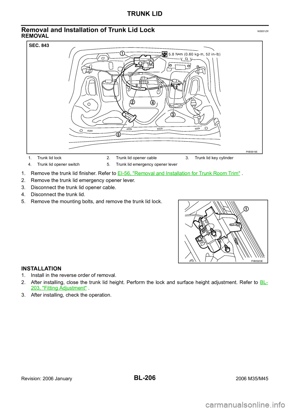
Removal and Installation of Trunk Lid LockNIS001ZK
REMOVAL
1. Remove the trunk lid finisher. Refer to EI-56, "Removal and Installation for Trunk Room Trim" .
2. Remove the trunk lid emergency opener lever.
3. Disconnect the trunk lid opener cable.
4. Disconnect the trunk lid.
5. Remove the mounting bolts, and remove the trunk lid lock.
INSTALLATION
1. Install in the reverse order of removal.
2. After installing, close the trunk lid height. Perform the lock and surface height adjustment. Refer to BL-
203, "Fitting Adjustment" .
3. After installing, check the operation.
1. Trunk lid lock 2. Trunk lid opener cable 3. Trunk lid key cylinder
4. Trunk lid opener switch 5. Trunk lid emergency opener lever
PIIB5819E
PIIB5820E
Page 1146 of 5621
TRUNK LID
BL-207
C
D
E
F
G
H
J
K
L
MA
B
BL
Revision: 2006 January2006 M35/M45
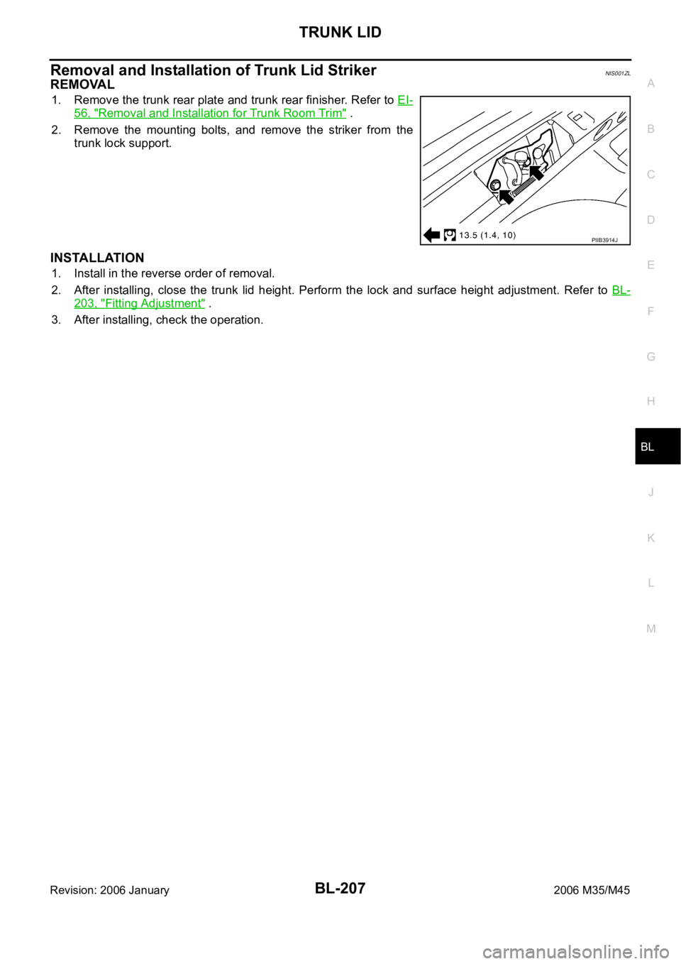
Removal and Installation of Trunk Lid StrikerNIS001ZL
REMOVAL
1. Remove the trunk rear plate and trunk rear finisher. Refer to EI-
56, "Removal and Installation for Trunk Room Trim" .
2. Remove the mounting bolts, and remove the striker from the
trunk lock support.
INSTALLATION
1. Install in the reverse order of removal.
2. After installing, close the trunk lid height. Perform the lock and surface height adjustment. Refer to BL-
203, "Fitting Adjustment" .
3. After installing, check the operation.
PIIB3914J
Page 1147 of 5621
BL-208
TRUNK LID
Revision: 2006 January2006 M35/M45
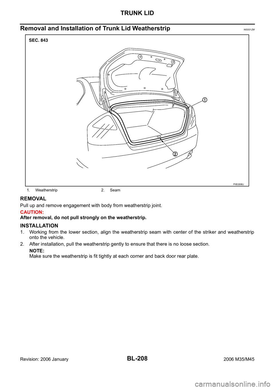
Removal and Installation of Trunk Lid WeatherstripNIS001ZM
REMOVAL
Pull up and remove engagement with body from weatherstrip joint.
CAUTION:
After removal, do not pull strongly on the weatherstrip.
INSTALLATION
1. Working from the lower section, align the weatherstrip seam with center of the striker and weatherstrip
onto the vehicle.
2. After installation, pull the weatherstrip gently to ensure that there is no loose section.
NOTE:
Make sure the weatherstrip is fit tightly at each corner and back door rear plate.
1. Weatherstrip 2. Seam
PIIB3898J
Page 1155 of 5621
BL-216
TRUNK LID OPENER
Revision: 2006 January2006 M35/M45
Trouble DiagnosisNIS001ZS
TRUNK DOSE NOT OPEN WITH TRUNK LID OPENER SWITCH / WITH INTELLIGENT KEY
1. CHECK TRUNK LID OPENER CANCEL SWITCH
Check trunk lid opener cancel switch position.
Does trunk lid opener cancel switch turn OFF (CANCEL)?
Yes >> Turn on trunk lid opener cancel switch.
No >> GO TO 2.
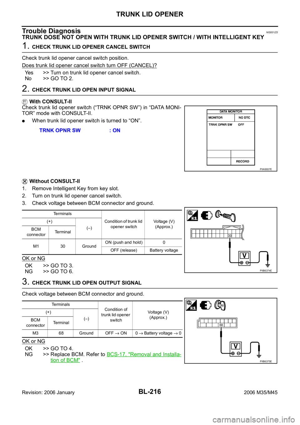
2. CHECK TRUNK LID OPEN INPUT SIGNAL
With CONSULT-II
Check trunk lid opener switch (“TRNK OPNR SW”) in “DATA MONI-
TOR” mode with CONSULT-II.
When trunk lid opener switch is turned to “ON”.
Without CONSULT-II
1. Remove Intelligent Key from key slot.
2. Turn on trunk lid opener cancel switch.
3. Check voltage between BCM connector and ground.
OK or NG
OK >> GO TO 3.
NG >> GO TO 6.
3. CHECK TRUNK LID OPEN OUTPUT SIGNAL
Check voltage between BCM connector and ground.
OK or NG
OK >> GO TO 4.
NG >> Replace BCM. Refer to BCS-17, "
Removal and Installa-
tion of BCM" . TRNK OPNR SW : ON
PIIA9937E
Terminals
Condition of trunk lid
opener switchVoltage (V)
(Approx.) (+)
(–)
BCM
connectorTerminal
M1 30 GroundON (push and hold) 0
OFF (release) Battery voltage
PIIB6374E
Te r m i n a l s
Condition of
trunk lid opener
switchVoltage (V)
(Approx.) (+)
(–)
BCM
connectorTerminal
M3 68 Ground OFF
ON 0 Battery voltage 0
PIIB6375E
Page 1180 of 5621
VEHICLE SECURITY (THEFT WARNING) SYSTEM
BL-241
C
D
E
F
G
H
J
K
L
MA
B
BL
Revision: 2006 January2006 M35/M45
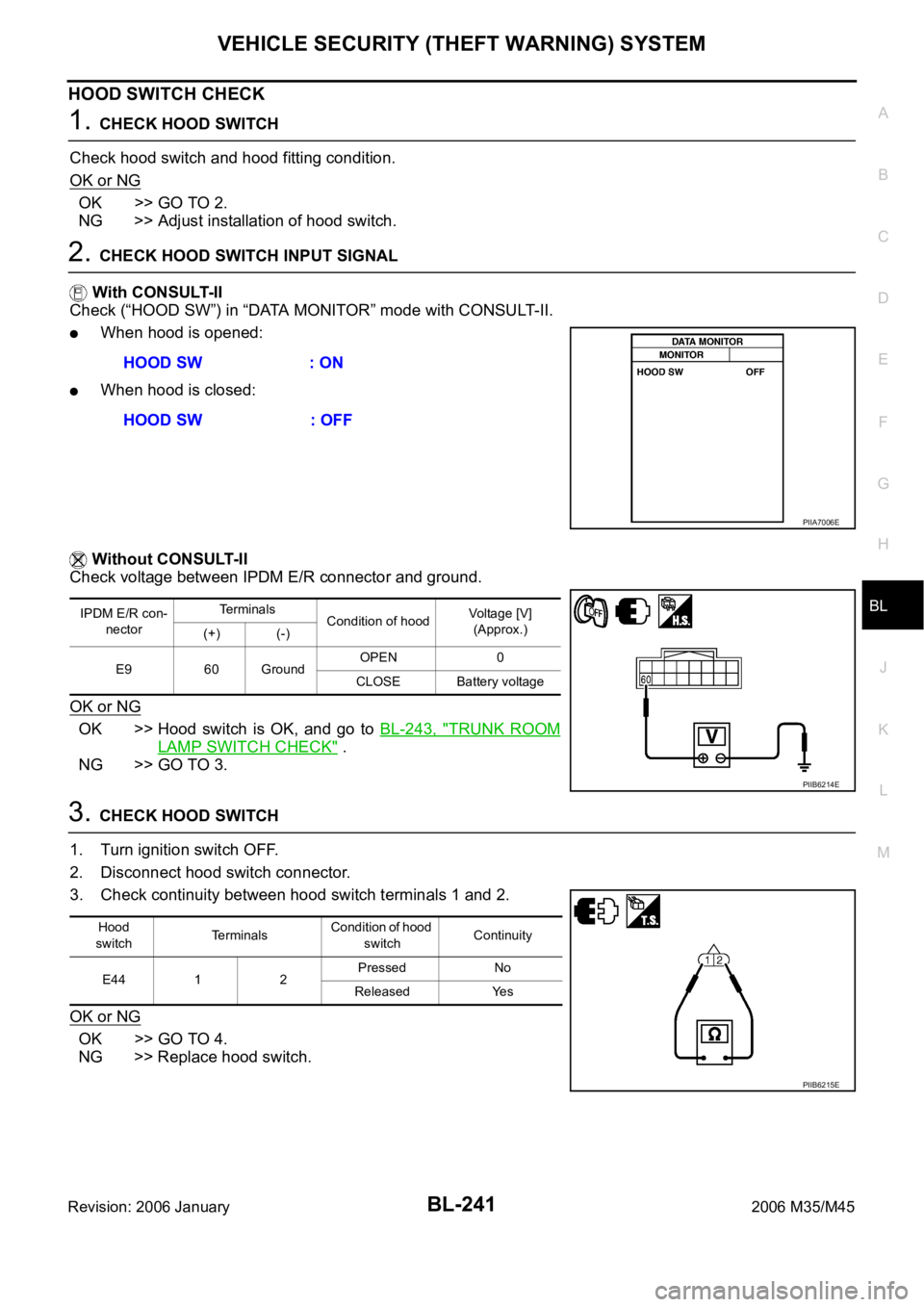
HOOD SWITCH CHECK
1. CHECK HOOD SWITCH
Check hood switch and hood fitting condition.
OK or NG
OK >> GO TO 2.
NG >> Adjust installation of hood switch.
2. CHECK HOOD SWITCH INPUT SIGNAL
With CONSULT-II
Check (“HOOD SW”) in “DATA MONITOR” mode with CONSULT-II.
When hood is opened:
When hood is closed:
Without CONSULT-II
Check voltage between IPDM E/R connector and ground.
OK or NG
OK >> Hood switch is OK, and go to BL-243, "TRUNK ROOM
LAMP SWITCH CHECK" .
NG >> GO TO 3.
3. CHECK HOOD SWITCH
1. Turn ignition switch OFF.
2. Disconnect hood switch connector.
3. Check continuity between hood switch terminals 1 and 2.
OK or NG
OK >> GO TO 4.
NG >> Replace hood switch.HOOD SW : ON
HOOD SW : OFF
PIIA7006E
IPDM E/R con-
nectorTe r m i n a l s
Condition of hoodVoltage [V]
(Approx.)
(+) (-)
E9 60 GroundOPEN 0
CLOSE Battery voltage
PIIB6214E
Hood
switchTerminalsCondition of hood
switchContinuity
E44 1 2Pressed No
Released Yes
PIIB6215E
Page 1189 of 5621

BL-250
IVIS (INFINITI VEHICLE IMMOBILIZER SYSTEM-NATS)
Revision: 2006 January2006 M35/M45
System DescriptionNIS0020D
DESCRIPTION
The IVIS (NATS) is an anti-theft system by registering an Intelligent Key ID in to the vehicle and prevents
the engine being started by an unregistered Intelligent Key. It has a higher protection against auto thefts
that duplicates mechanical key.
It performs the ID verification when starting the engine in the same way as the Intelligent Key system. But,
it performs the IVIS (NATS) ID verification when inserting the Intelligent Key and performs the Intelligent
Key ID verification when carrying the Intelligent Key.
The Intelligent Key system of FUGA (Y50) is not the same as the conventional models. The mechanical
key integrated in the Intelligent Key cannot start the engine. When the Intelligent Key battery is dis-
charged, the IVIS (NATS) ID verification memorized to the transponder integrated with Intelligent Key is
performed by inserting the Intelligent Key into the key slot. If the verification results are OK, the engine
start operation can be performed by the push-button ignition switch operation.
Locate the security indicator and apply the anti-theft system equipment sticker, forewarn that the IVIS
(NATS) is onboard with the model.
The security indicator always blinks when the Intelligent Key is removed from the key slot and when the
power supply position is in LOCK position.
Intelligent Key can be registered up to 4 keys (Including the standard ignition key) on request from the
owner.
The specified registration is required when replacing ECM, BCM or Intelligent Key. The registrations pro-
cedure for IVIS (NATS) and registration procedure for Intelligent Key when installing the Intelligent Key
unit, refer to CONSULT-II Operation Manual NATS-IVIS/NVIS.
Possible symptom of IVIS (NATS) malfunction is “Engine cannot start”. In FUGA (Y50), the engine can be
started with the Intelligent Key system and IVIS (NATS). Identify the possible causes according to “Work
Flow”, Refer to BL-272, "
Work Flow" .
If ECM other than Genuine NISSAN is installed, the engine cannot be started. For ECM replacement pro-
cedure, refer to BL-252, "
ECM Re-Communicating Function" .
PRECAUTIONS FOR KEY REGISTRATION
The key registration is a procedure that erases the current IVIS (NATS) ID once, and then re register a
new ID operation. Therefore the registered Intelligent Key is necessary for this procedure. Before starting
the registration operation collect all registered Intelligent Key from the customer
When registering the Intelligent Key, 2 registration procedures [IVIS (NATS) ID registration and Intelligent
Key ID registration] should be performed. The IVIS (NATS) ID registration is the procedure that registers
the ID stored into the transponder (integrated into Intelligent Key) to the BCM. The Intelligent Key ID reg-
istration is the procedure that registers the ID to the Intelligent Key unit. Each registration procedure
should be done separated.
When performing the Intelligent Key system registration only, the engine cannot be started by inserting the
key into the key slot. When performing the IVIS (NATS) registration only, the engine cannot be started by
the operation when carrying the key. The registrations of both systems should be performed.
SECURITY INDICATOR
Warn the outside that the vehicle is the model with IVIS (NATS).
The security indicator always blinks when the Intelligent Key is removed from the key slot and when the
ignition switch is in LOCK position.
NOTE:
Because security indicator is highly efficient, the battery is barely affected.
Page 1191 of 5621

BL-252
IVIS (INFINITI VEHICLE IMMOBILIZER SYSTEM-NATS)
Revision: 2006 January2006 M35/M45
Unless each start condition is fulfilled, the engine will not response regardless of how many times the
push-button ignition switch is pushed. At that time, illumination repeats the position in the order of LOCK
ACC ON LOCK.
*1: When the A/T selector lever position is N position, the engine start condition is different according to the vehicle speed.
At vehicle speed of 5 km/h or less, the engine can start only when the brake pedal is depressed.
At vehicle speed of 5 km/h or more, the engine can start even if the brake pedal is not depressed. (It is the same as “Engine stall
return operation while driving”.)
*2: When the A/T selector lever position is in any position other than P position and when the vehicle speed is 5 km/h or more, the
engine stop condition is different.
Press and hold the push-button ignition switch for 2 seconds or more. (When the push-button ignition switch is pressed for too short
a time, the operation may be invalid, so properly press and hold to prevent the incorrect operation.)
Press the push-button ignition switch 3 times within 1.5 seconds. (Emergency stop operation)
ECM Re-Communicating FunctionNIS0020F
Performing following procedure can automatically perform re-communication of ECM and BCM or Intelligent
Key unit, but only when the ECM has been replaced with a new one (*1).
*1: New one means a virgin ECM which has never been energized on-board.
(In this step, initialization procedure by CONSULT-II is not necessary)
NOTE:
When registering new Key IDs or replacing the ECM other than brand new, refer to CONSULT-II
Operation Manual NATS-IVIS/NVIS.
If multiple keys are attached to the key holder, separate them before work.
Distinguish keys with unregistered key ID from those with registered ID.
1. Install ECM.
2. Insert the registered Intelligent Key (*2), turn ignition switch to “ON”.
*2: To perform this step, use the key that has been used before performing ECM replacement.
3. Maintain ignition switch in “ON” position for at least 5 seconds.
4. Turn ignition switch to “OFF”.
Power supply positionEngine start/stop condition
Engine switch operation fre-
quency
Brake pedal A/T selector lever position
LOCK
ACCNot depressed
(When A/T selector lever is in
any position other than P or N,
there will be no effect even if it
is depressed.)Any position other than P or N
(When the brake pedal is not
depressed, there will be no
effect even if the A/T selector
lever is in P or N position.)1
LOCK
ACC ONNot depressed
(When A/T selector lever is in
any position other than P or N,
there will be no effect even if it
is depressed.)Any position other than P or N
(When the brake pedal is not
depressed, there will be no
effect even if the A/T selector
lever is in P or N position.)2
LOCK
ACC ON LOCKNot depressed
(When A/T selector lever is in
any position other than P or N,
there will be no effect even if it
is depressed.)Any position other than P or N
(When the brake pedal is not
depressed, there will be no
effect even if the A/T selector
lever is in P or N position.)3
LOCK
START
ACC
START
ON
START
(Engine start)Depressed P or N position (*1)1
[If the switch is pushed once,
the engine starts from any
power supply position (LOCK,
ACC, and ON)]
Engine start condition
LOCK
(Engine stop)— P position 1
Engine start condition
ACC
(Engine stop)— Any position other than P (*2) 1
Engine stall return operation
while driving—N position 1
Page 1211 of 5621

BL-272
IVIS (INFINITI VEHICLE IMMOBILIZER SYSTEM-NATS)
Revision: 2006 January2006 M35/M45
“NATS I-KEY” SELF-DIAGNOSTIC RESULTS ITEM CHART
Work FlowNIS0020O
1. LISTEN TO CUSTOMER COMPLAINT OR REQUEST
Get symptoms or listen to customer complaints or request.
NOTE:
In case of request for Intelligent Key or IVIS (NATS) system repair, the key ID re-registration might be neces-
sary. Keep all the Intelligent Keys before work for the re-registration.
Key ID registration request>>Register Intelligent Key by referring to CONSULT-II operation manual IVIS/
NVIS NATS.
Request for malfunction repair.>>GO TO 2.
2. CHECK DOOR LOCK AND REMOTE CONTROL FUNCTION
Check that Door Lock and remote control function of Intelligent Key operate normally.
Door Lock or remote control function is malfunctioning.>>Malfunction of Door Lock and remote control func-
tion, Refer to
Door Lock and remote control function are normal.>>GO TO 3.
DISCORD BCM-I-KEY
[B2194]The ID verification results
between BCM and Intelligent
Key unit are NG.Short circuit in communication
line between BCM and Intelli-
gent Key unit to power supply
lineMalfunction have occurred in
CAN communication
Check “Self-diagnostic Results”
of “Intelligent Key” using CON-
SULT-II. Refer to BL-152,
"SELF-DIAGNOSTIC
RESULTS" . Short circuit in communication
line between BCM and ECM to
ground
Intelligent Key unit malfunctionBL-125
ANTI-SCANNING
[B2195]A remote control starter that is
not Genuine NISSAN is
installedIf a remote control starter that is
not Genuine NISSAN is
installed, the anti-theft system
is activated and the engine may
not be started. In this case,
remove the parts after the cus-
tomer understands the situa-
tion.— Suspect Systems Description Possible malfunction Action to take/Reference page
Suspect Systems Description Possible malfunction Action to take/Reference page
NO DTC NO DTC — —
DISCORD BCM-I-KEY
[B2590]The ID verification results
between Intelligent Key unit
and BCM are NG.Short circuit in communication
line between BCM and Intelli-
gent Key unit to power supply
lineMalfunction have occurred in
CAN communication
Check “Self-diagnostic Results”
of “Intelligent Key” using CON-
SULT-II. Refer to BL-152,
"SELF-DIAGNOSTIC
RESULTS" . Short circuit in communication
line between BCM and ECM to
ground
BCM malfunctionBCS-17