Page 1133 of 5621
BL-194
DOOR
Revision: 2006 January2006 M35/M45
Door WeatherstripNIS001ZC
FRONT DOOR
REMOVAL
1. Remove the mounting bolts of the check link on the vehicle. Refer to BL-191, "Removal and Installation of
Front Door" or BL-192, "Removal and Installation of Rear Door" .
2. Remove the weatherstrip clips and remove weatherstrip.
CAUTION:
After removal, do not pull strongly on the weatherstrip.
INSTALLATION
Install in the reverse order of removal.
Install the door weatherstrip (A) and along the arrow direction.
1. Door weatherstrip 2. Front door 3. Door sash molding
PIIB3878J
Page 1134 of 5621
DOOR
BL-195
C
D
E
F
G
H
J
K
L
MA
B
BL
Revision: 2006 January2006 M35/M45
REAR DOOR
REMOVAL
1. Remove the mounting bolts of the check link on the vehicle. Refer to BL-191, "Removal and Installation of
Front Door" or BL-192, "Removal and Installation of Rear Door" .
2. Remove the weatherstrip clips and remove weatherstrip.
CAUTION:
After removal, do not pull strongly on the weatherstrip.
INSTALLATION
Install in the reverse order of removal.
Install the door weatherstrip (A) and along the arrow direction.
1. Door weatherstrip 2. Rear door 3. Door sash molding
PIIB3879J
Page 1135 of 5621
BL-196
FRONT DOOR LOCK
Revision: 2006 January2006 M35/M45
FRONT DOOR LOCKPFP:80502
Component StructureNIS001ZD
Removal and InstallationNIS001ZE
REMOVAL
1. Remove the front door finisher. Refer toEI-34, "Removal and Installation" .
2. Disconnect the inside handle knob cable and lock knob cable
from the back side of the front door finisher.
3. Remove the front door window and front door module assembly. Refer toGW-63, "
FRONT DOOR GLASS
AND REGULATOR" .
4. Remove door side grommet, and remove door key cylinder assembly (driver side) and outside handle
escutcheon (passenger side) bolts (TORX T30) from grommet hole.
1. Outside handle 2. Front gasket 3. Lock knob cable
4. Inside handle 5. Inside handle knob cable 6. Door lock assembly
7. Outside handle cable 8. Key cylinder rod (Driver side only) 9. Outside handle bracket
10. Grommet 11. Rear gasket 12. Door key cylinder assembly (Driver
side)
Outside handle escutcheon (Pas-
senger side)
PIIB5806E
PIIB4933E
Page 1138 of 5621
FRONT DOOR LOCK
BL-199
C
D
E
F
G
H
J
K
L
MA
B
BL
Revision: 2006 January2006 M35/M45
16. Reach to separate the outside handle cable connection.
INSTALLATION
Install in the reverse order of removal.
CAUTION:
To install each rod, be sure to rotate the rod holder until a click is felt.
PIIB5815E
Page 1139 of 5621
BL-200
REAR DOOR LOCK
Revision: 2006 January2006 M35/M45
REAR DOOR LOCKPFP:82502
Component StructureNIS001ZF
Removal and InstallationNIS001ZG
REMOVAL
1. Remove the rear door finisher. Refer toEI-34, "Removal and Installation" .
2. Disconnect the inside handle knob cable and lock knob cable
from the back side of the rear door finisher.
3. Remove the rear door sash. Refer toGW-67, "
REAR DOOR GLASS AND REGULATOR" .
4. Remove the rear door window and rear door screen assembly. Refer toGW-67, "
REAR DOOR GLASS
AND REGULATOR" .
5. Remove door side grommet, and remove outside handle escutcheon bolt (TORX T30) from grommet
hole.
1. Outside handle 2. Front gasket 3. Inside handle
4. Lock knob cable 5. Inside handle knob cable 6. Door lock assembly
7. Outside handle cable 8. Outside handle bracket 9. Grommet
10. Rear gasket 11. Outside handle escutcheon
PIIB5816E
PIIB4933E
Page 1141 of 5621
BL-202
REAR DOOR LOCK
Revision: 2006 January2006 M35/M45
9. Remove the TORX bolts (T30), remove the door lock assembly.
10. Remove the TORX bolt (T30), and remove the outside handle
bracket.
11. While pulling outside handle, slide toward rear of vehicle to
remove outside handle.
12. Disconnect the door lock actuator connector and remove the door lock assembly.
13. Reach to separate outside handle cable connection.
INSTALLATION
Install in the reverse order of removal.
CAUTION:
To install each rod, be sure to rotate the rod holder until a click is felt.
PIIB5812E
PIIB5813E
PIIB5814E
PIIB5815E
Page 1143 of 5621

BL-204
TRUNK LID
Revision: 2006 January2006 M35/M45
Loosen the striker mounting bolts.
Lift up the trunk lid approx. 100 - 150 mm (3.94 - 5.91 in) height then close it lightly and make sure it
engaged firmly with the trunk lid closed.
Check the clearance and evenness.
Finally tighten the trunk lid striker.
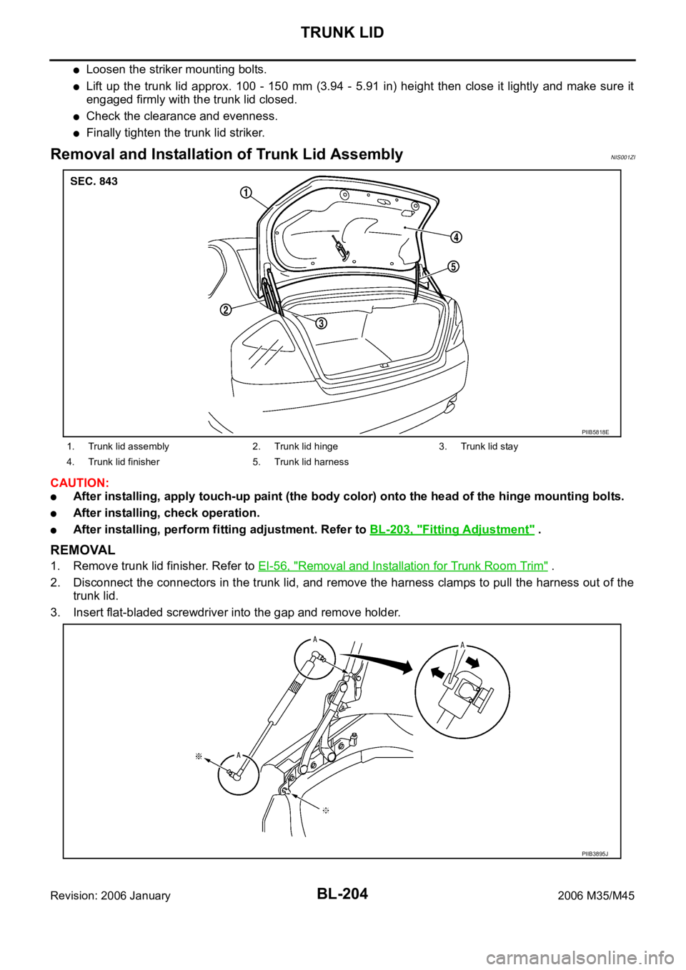
Removal and Installation of Trunk Lid AssemblyNIS001ZI
CAUTION:
After installing, apply touch-up paint (the body color) onto the head of the hinge mounting bolts.
After installing, check operation.
After installing, perform fitting adjustment. Refer to BL-203, "Fitting Adjustment" .
REMOVAL
1. Remove trunk lid finisher. Refer to EI-56, "Removal and Installation for Trunk Room Trim" .
2. Disconnect the connectors in the trunk lid, and remove the harness clamps to pull the harness out of the
trunk lid.
3. Insert flat-bladed screwdriver into the gap and remove holder.
1. Trunk lid assembly 2. Trunk lid hinge 3. Trunk lid stay
4. Trunk lid finisher 5. Trunk lid harness
PIIB5818E
PIIB3895J
Page 1144 of 5621
TRUNK LID
BL-205
C
D
E
F
G
H
J
K
L
MA
B
BL
Revision: 2006 January2006 M35/M45
4. Remove trunk lid stay (gas stay).
WAR NING :
Body injury may occur if no supporting rod is holding the
trunk lid open when removing the damper stay.
5. Remove the mounting bolts, and remove the trunk lid assembly.
INSTALLATION
Install in the reverse order of removal.
Removal and Installation of Trunk Lid StayNIS001ZJ
REMOVAL
1. Insert flat-bladed screwdriver into the gap and remove holder.
2. Remove trunk lid stay on the trunk lid.
3. Remove the stud balls, and trunk lid stay.
INSTALLATION
1. Install in the reverse order of removal.
2. After installing, check the operation.
PIIB4909J
PIIB3895J