Page 962 of 5621
FRONT FENDER
BL-23
C
D
E
F
G
H
J
K
L
MA
B
BL
Revision: 2006 January2006 M35/M45
FRONT FENDERPFP:63100
Removal and InstallationNIS001WO
REMOVAL
1. Remove the front bumper. Refer to EI-11, "Removal and Installation" .
2. Remove the headlamp. Refer to LT-41, "
Removal and Installation" .
3. Remove the turn signal lamp. Refer to LT-229, "
Removal and Installation of Front Turn Signal Lamp" .
4. Remove the front fender protector. Refer to EI-20, "
FENDER PROTECTOR" .
5. Remove the center mud guard. Refer toEI-22, "
Removal and Installation" .
6. Remove the mounting bolt and remove the front fender.
CAUTION:
While removing use a shop cloth to protect body from damaging.
INSTALLATION
Install in the reverse order of removal.
CAUTION:
After installing, apply touch-up paint (the body color) onto the head of the front fender mounting
bolts.
After installing, check front fender adjustment. Refer to BL-15, "Fitting Adjustment" and BL-190,
"Fitting Adjustment" .
PIIB3893J
Page 974 of 5621

POWER DOOR LOCK SYSTEM
BL-35
C
D
E
F
G
H
J
K
L
MA
B
BL
Revision: 2006 January2006 M35/M45
Power Supply and Ground Circuit Check of BCMNIS001WZ
1. CHECK FUSE
Check the following fuse and fusible link.
50A fusible link (letter F , located in the fuse and fusible link box)
10A fuse [No.21, located in the fuse block (J/B)]
10A fuse [No.6, located in the fuse block (J/B)]
15A fuse [No.1, located in the fuse block (J/B)]
NOTE:
Refer to BL-24, "
Component Parts and Harness Connector Location" .
OK or NG
OK >> GO TO 2.
NG >> If fuse is blown, be sure to eliminate cause of malfunction before installing new fuse, refer to PG-
3, "POWER SUPPLY ROUTING CIRCUIT" .
2. CHECK POWER SUPPLY CIRCUIT
1. Turn ignition switch OFF.
2. Disconnect BCM connectors.
3. Check voltage between BCM and ground.
OK or NG
OK >> GO TO 3.
NG >> Repair or replace BCM power supply circuit.
3. CHECK GROUND CIRCUIT
Check continuity between BCM harness connector and ground.
OK or NG
OK >> Power supply and ground circuit are OK.
NG >> Repair or replace BCM ground circuit.
Terminals Condition
of ignition
switch
positionVoltage (V)
(Approx.) (+)
(–)
BCM connector Terminal
M311
GroundACC
Battery voltage 38 ON
M442
OFF
55
PIIB6296E
BCM connector Terminal Continuity
M2 52 Ground Yes
PIIB5935E
Page 1064 of 5621

INTELLIGENT KEY SYSTEM
BL-125
C
D
E
F
G
H
J
K
L
MA
B
BL
Revision: 2006 January2006 M35/M45
Check Warning Chime FunctionNIS001Y4
1. CHECK WARNING CHIME INTO COMBINATION METER OPERATION
With CONSULT-II
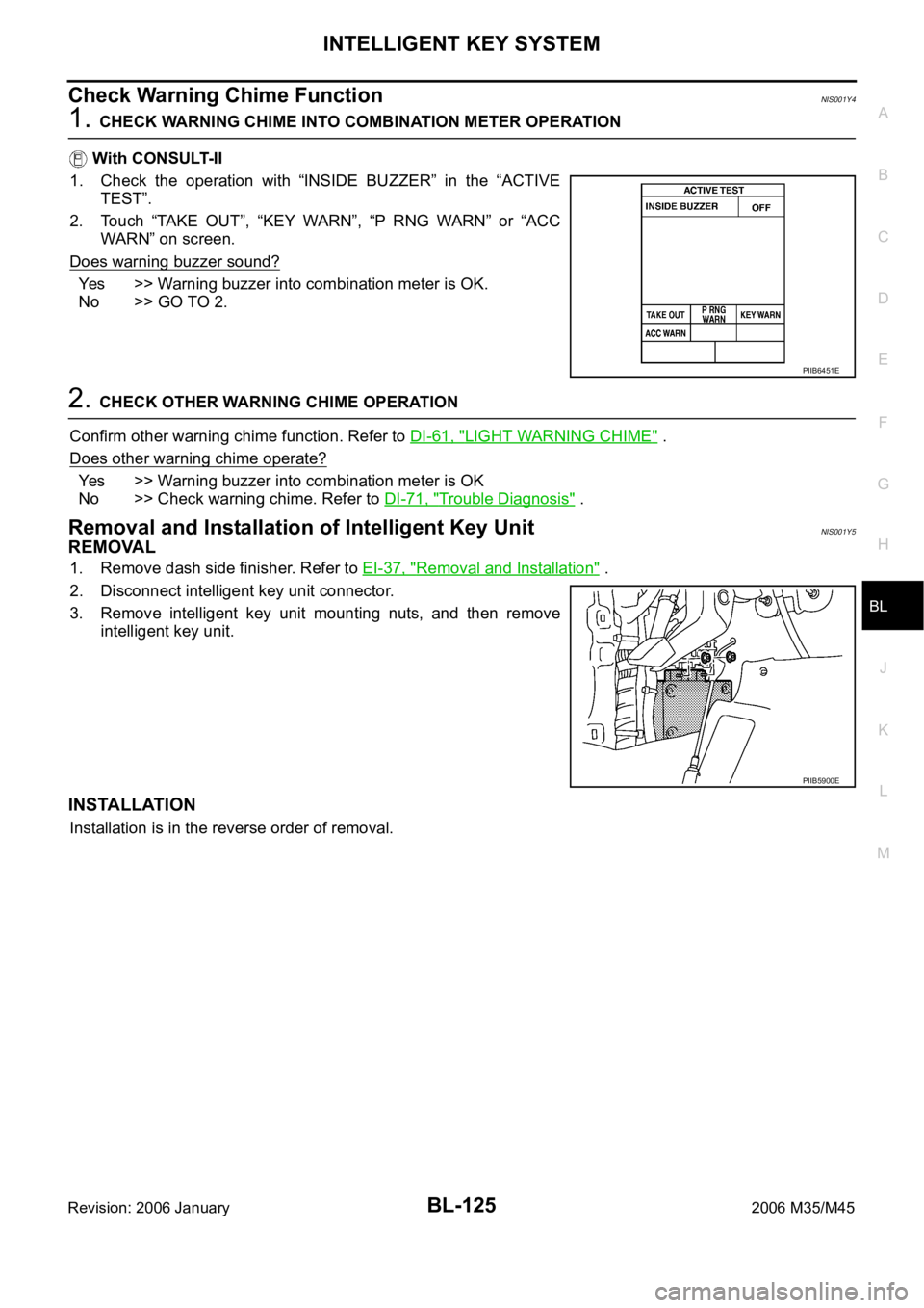
1. Check the operation with “INSIDE BUZZER” in the “ACTIVE
TEST”.
2. Touch “TAKE OUT”, “KEY WARN”, “P RNG WARN” or “ACC
WARN” on screen.
Does warning buzzer sound?
Yes >> Warning buzzer into combination meter is OK.
No >> GO TO 2.
2. CHECK OTHER WARNING CHIME OPERATION
Confirm other warning chime function. Refer to DI-61, "
LIGHT WARNING CHIME" .
Does other warning chime operate?
Yes >> Warning buzzer into combination meter is OK
No >> Check warning chime. Refer to DI-71, "
Trouble Diagnosis" .
Removal and Installation of Intelligent Key UnitNIS001Y5
REMOVAL
1. Remove dash side finisher. Refer to EI-37, "Removal and Installation" .
2. Disconnect intelligent key unit connector.
3. Remove intelligent key unit mounting nuts, and then remove
intelligent key unit.
INSTALLATION
Installation is in the reverse order of removal.
PIIB6451E
PIIB5900E
Page 1070 of 5621

INTELLIGENT KEY SYSTEM/ENGINE START FUNCTION
BL-131
C
D
E
F
G
H
J
K
L
MA
B
BL
Revision: 2006 January2006 M35/M45
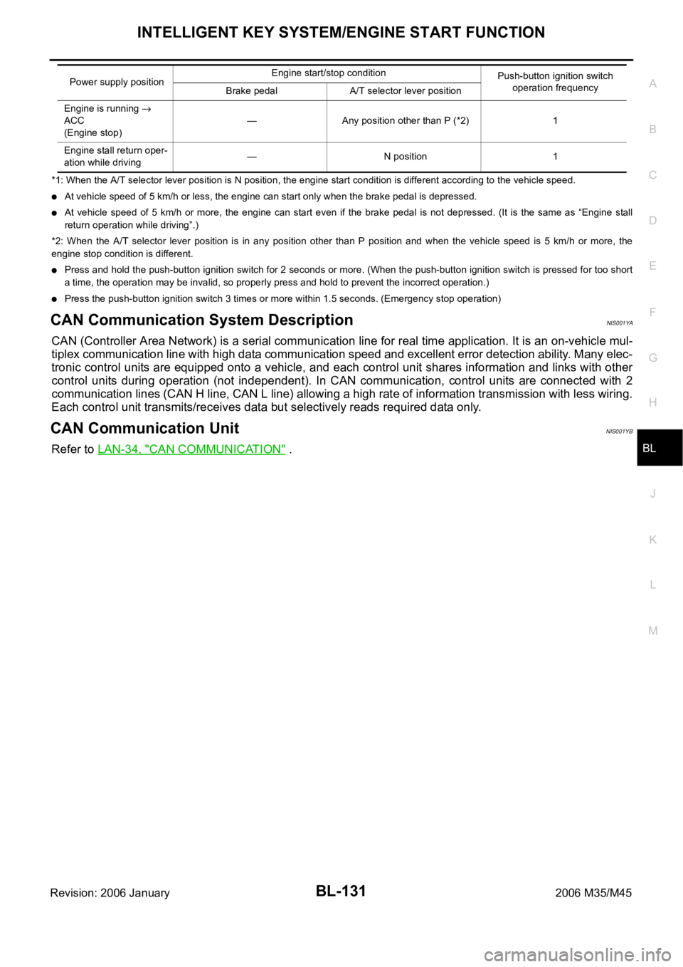
*1: When the A/T selector lever position is N position, the engine start condition is different according to the vehicle speed.
At vehicle speed of 5 km/h or less, the engine can start only when the brake pedal is depressed.
At vehicle speed of 5 km/h or more, the engine can start even if the brake pedal is not depressed. (It is the same as “Engine stall
return operation while driving”.)
*2: When the A/T selector lever position is in any position other than P position and when the vehicle speed is 5 km/h or more, the
engine stop condition is different.
Press and hold the push-button ignition switch for 2 seconds or more. (When the push-button ignition switch is pressed for too short
a time, the operation may be invalid, so properly press and hold to prevent the incorrect operation.)
Press the push-button ignition switch 3 times or more within 1.5 seconds. (Emergency stop operation)
CAN Communication System DescriptionNIS001YA
CAN (Controller Area Network) is a serial communication line for real time application. It is an on-vehicle mul-
tiplex communication line with high data communication speed and excellent error detection ability. Many elec-
tronic control units are equipped onto a vehicle, and each control unit shares information and links with other
control units during operation (not independent). In CAN communication, control units are connected with 2
communication lines (CAN H line, CAN L line) allowing a high rate of information transmission with less wiring.
Each control unit transmits/receives data but selectively reads required data only.
CAN Communication UnitNIS001YB
Refer to LAN-34, "CAN COMMUNICATION" .
Engine is running
ACC
(Engine stop)— Any position other than P (*2) 1
Engine stall return oper-
ation while driving— N position 1 Power supply positionEngine start/stop condition
Push-button ignition switch
operation frequency
Brake pedal A/T selector lever position
Page 1129 of 5621
BL-190
DOOR
Revision: 2006 January2006 M35/M45
DOORPFP:80100
Fitting AdjustmentNIS001Z9
FRONT DOOR
Longitudinal Clearance and Surface Height Adjustment At Front End
Loosen the hinge mounting bolts. Raise the front door at rear end to adjust.
REAR DOOR
Longitudinal Clearance and Surface Height Adjustment At Front End
1. Remove the center pillar upper garnish and center pillar lower garnish. Refer to EI-37, "Removal and
Installation" .
1. Front fender 2. Front door outer 3. Rear door outer
4. Rear fender
PIIB5805E
Page 1130 of 5621

DOOR
BL-191
C
D
E
F
G
H
J
K
L
MA
B
BL
Revision: 2006 January2006 M35/M45
2. Accessing from inside the vehicle, loosen the mounting nuts. Open the rear door, and raise the rear door
at rear end to adjust.
STRIKER ADJUSTMENT
1. Adjust the striker so that it becomes parallel with the lock inser-
tion direction.
Removal and Installation of Front DoorNIS001ZA
CAUTION:
When removing and installing the front door assembly, support the door with a jack and cloth to
protect the door and body.
When removing and installing front door assembly, be sure to carry out the fitting adjustment.
Refer to BL-190, "
Fitting Adjustment" .
After installing, apply touch-up paint (the body color) onto the head of the hinge mounting nuts.
Check the hinge rotating part for poor lubrication. If necessary, apply “body grease”.
Operate with two workers, because of its heavy weight.
Check rear door open/close operation after installation.
REMOVAL
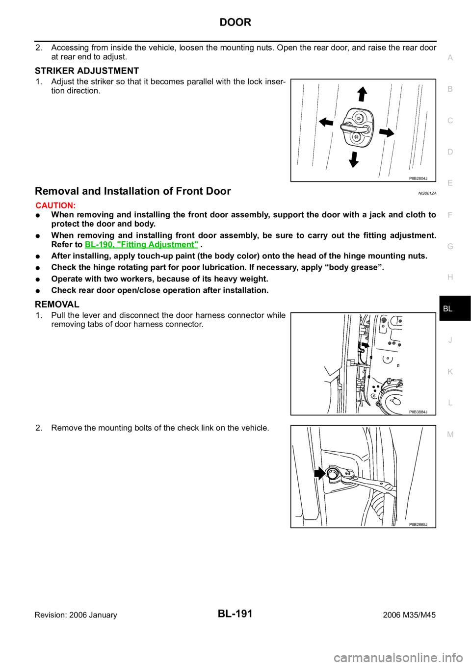
1. Pull the lever and disconnect the door harness connector while
removing tabs of door harness connector.
2. Remove the mounting bolts of the check link on the vehicle.
PIIB2804J
PIIB3884J
PIIB2865J
Page 1131 of 5621
BL-192
DOOR
Revision: 2006 January2006 M35/M45
3. Remove the door-side hinge mounting nuts, then remove the
door assembly.
INSTALLATION
Install in the reverse order of removal.
Removal and Installation of Rear DoorNIS001ZB
CAUTION:
When removing and installing the rear door assembly, support the door with a jack and cloth to
protect the door and body.
When removing and installing rear door assembly, be sure to carry out the fitting adjustment.
Refer to BL-190, "
Fitting Adjustment" .
Check the hinge rotating part for poor lubrication. If necessary, apply “body grease”.
After installing, apply touch-up paint (the body color) onto the head of the hinge mounting nuts.
Operate with two workers, because of its heavy weight.
Check rear door open/close operation after installation.
REMOVAL
1. Pull out grommet and disconnect rear door harness connector.
2. Remove the mounting bolts of the check link on the vehicle.
PIIB3912J
PIIB3913J
PIIB2865J
Page 1132 of 5621
DOOR
BL-193
C
D
E
F
G
H
J
K
L
MA
B
BL
Revision: 2006 January2006 M35/M45
3. Remove the door-side hinge mounting nuts, and remove the
door assembly.
INSTALLATION
Install in the reverse order of removal.
PIIB3883J