2006 INFINITI M35 stop start
[x] Cancel search: stop startPage 5052 of 5621

DIFFERENTIAL GEAR OIL
RFD-9
C
E
F
G
H
I
J
K
L
MA
B
RFD
Revision: 2006 January2006 M35/M45
DIFFERENTIAL GEAR OILPFP:KLD30
Changing Differential Gear OilNDS000F3
DRAINING
1. Stop engine.
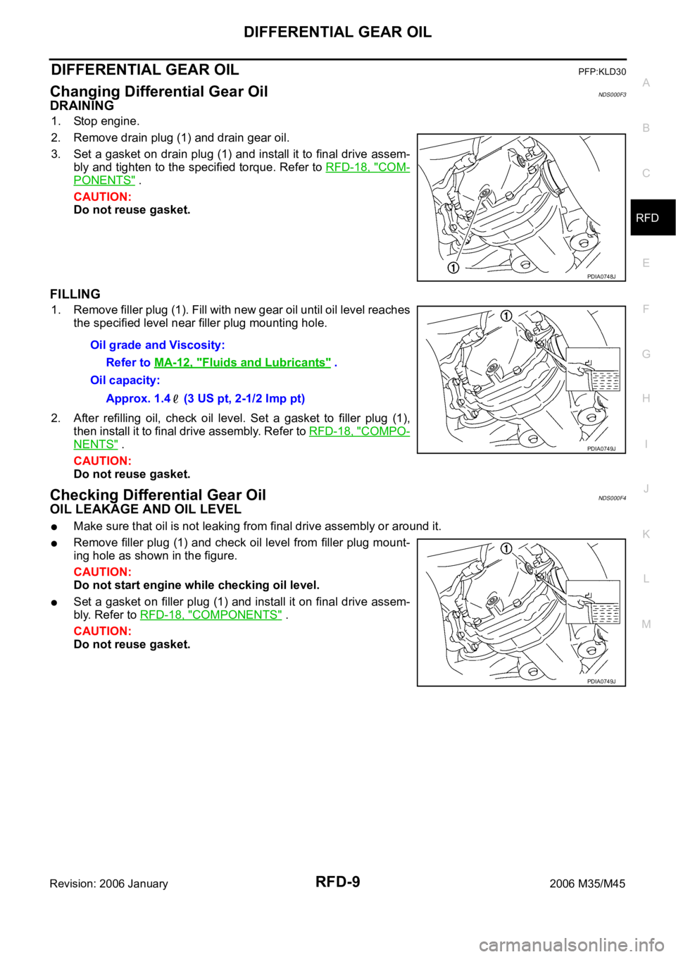
2. Remove drain plug (1) and drain gear oil.
3. Set a gasket on drain plug (1) and install it to final drive assem-
bly and tighten to the specified torque. Refer to RFD-18, "
COM-
PONENTS" .
CAUTION:
Do not reuse gasket.
FILLING
1. Remove filler plug (1). Fill with new gear oil until oil level reaches
the specified level near filler plug mounting hole.
2. After refilling oil, check oil level. Set a gasket to filler plug (1),
then install it to final drive assembly. Refer to RFD-18, "
COMPO-
NENTS" .
CAUTION:
Do not reuse gasket.
Checking Differential Gear OilNDS000F4
OIL LEAKAGE AND OIL LEVEL
Make sure that oil is not leaking from final drive assembly or around it.
Remove filler plug (1) and check oil level from filler plug mount-
ing hole as shown in the figure.
CAUTION:
Do not start engine while checking oil level.
Set a gasket on filler plug (1) and install it on final drive assem-
bly. Refer to RFD-18, "
COMPONENTS" .
CAUTION:
Do not reuse gasket.
PDIA0748J
Oil grade and Viscosity:
Refer to MA-12, "
Fluids and Lubricants" .
Oil capacity:
Approx. 1.4 (3 US pt, 2-1/2 Imp pt)
PDIA0749J
PDIA0749J
Page 5159 of 5621

SC-22
STARTING SYSTEM
Revision: 2006 January2006 M35/M45
VK45DE ENGINE MODELS
INSPECTION AFTER DISASSEMBLY
Pinion/Clutch Check
1. Inspect pinion teeth.
Replace pinion if teeth are worn or damaged. (Also check condition of ring gear teeth.)
2. Inspect reduction gear teeth.
Replace reduction gear if teeth are worn or damaged. (Also check condition of armature shaft gear
teeth.)
3. Check to see if pinion locks in one direction and rotates smoothly in the opposite direction.
If it locks or rotates in both directions, or unusual resistance is evident, replace.
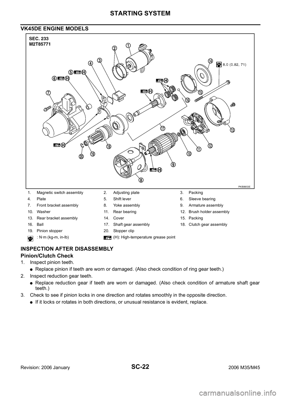
1. Magnetic switch assembly 2. Adjusting plate 3. Packing
4. Plate 5. Shift lever 6. Sleeve bearing
7. Front bracket assembly 8. Yoke assembly 9. Armature assembly
10. Washer 11. Rear bearing 12. Brush holder assembly
13. Rear bracket assembly 14. Cover 15. Packing
16. Ball 17. Shaft gear assembly 18. Clutch gear assembly
19. Pinion stopper 20. Stopper clip
: Nꞏm (kg-m, in-lb) (H): High-temperature grease point
PKIB8653E
Page 5165 of 5621

SC-28
CHARGING SYSTEM
Revision: 2006 January2006 M35/M45
Trouble Diagnoses with Battery/Starting/Charging System Tester (Charging)NKS003NP
NOTE:
To ensure a complete and thorough diagnosis, the battery, starter and alternator test segments must be done
as a set from start to finish.
Before starting, perform the preliminary inspection. Refer to SC-32, "
PRELIMINARY INSPECTION" .
1. Stop the operation of the power generation voltage variable control in either of the following procedures.
After selecting “ENGINE” of “SELECT SYSTEM” using CONSULT-II, set the DUTY value of “ALTERNA-
TOR DUTY” to 0% by selecting “ALTERNATOR DUTY” of “ACTIVE TEST”. Continue “ACTIVE TEST”
until the end of inspection. (When the DUTY value is 0 or 100%, the normal power generation is per-
formed according to the characteristic of the IC regulator of the alternator.)
Turn the ignition switch OFF, and disconnect the battery current sensor connector. [However, DTC
(P1550 - P1554) of the engine might remain. After finishing the inspection, connect the battery current
sensor connector and erase the self-diagnostic results history of the engine using CONSULT-II.]
2. Turn off all loads on the vehicle electrical system.
3. Perform battery and starting system test with Battery/Starting/
Charging system tester.
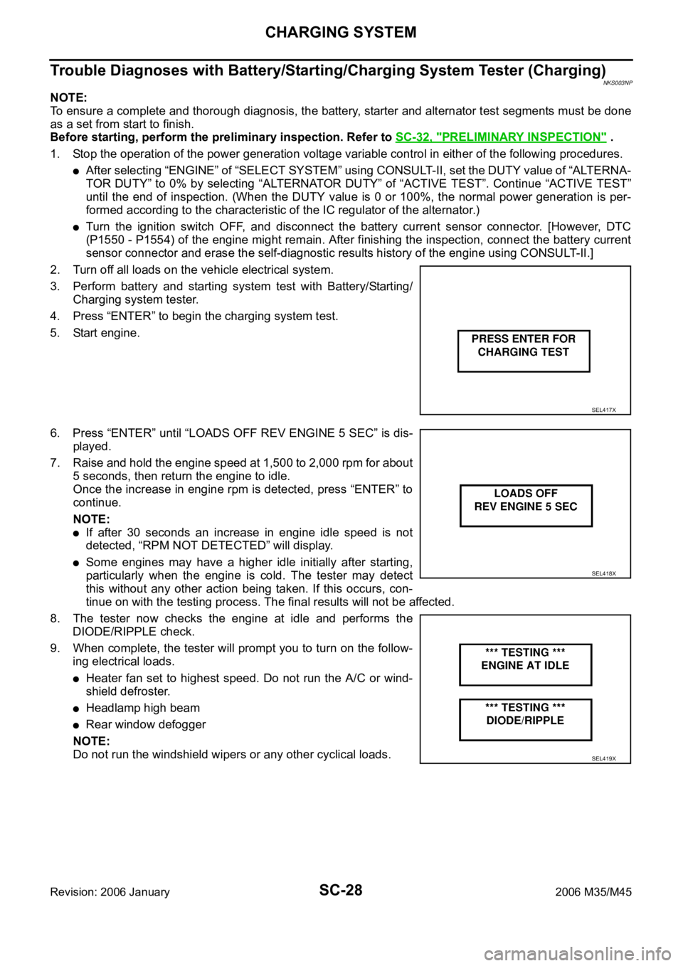
4. Press “ENTER” to begin the charging system test.
5. Start engine.
6. Press “ENTER” until “LOADS OFF REV ENGINE 5 SEC” is dis-
played.
7. Raise and hold the engine speed at 1,500 to 2,000 rpm for about
5 seconds, then return the engine to idle.
Once the increase in engine rpm is detected, press “ENTER” to
continue.
NOTE:
If after 30 seconds an increase in engine idle speed is not
detected, “RPM NOT DETECTED” will display.
Some engines may have a higher idle initially after starting,
particularly when the engine is cold. The tester may detect
this without any other action being taken. If this occurs, con-
tinue on with the testing process. The final results will not be affected.
8. The tester now checks the engine at idle and performs the
DIODE/RIPPLE check.
9. When complete, the tester will prompt you to turn on the follow-
ing electrical loads.
Heater fan set to highest speed. Do not run the A/C or wind-
shield defroster.
Headlamp high beam
Rear window defogger
NOTE:
Do not run the windshield wipers or any other cyclical loads.
SEL417X
SEL418X
SEL419X
Page 5180 of 5621

SERVICE DATA AND SPECIFICATIONS (SDS)
SC-43
C
D
E
F
G
H
I
J
L
MA
B
SC
Revision: 2006 January2006 M35/M45
SERVICE DATA AND SPECIFICATIONS (SDS)PFP:00030
BatteryNKS003NT
StarterNKS003NU
AlternatorNKS003NV
*: Adjustment range of power generation voltage variable control is 11.4 - 15.6 V. Ty p e110D26L
20 hour rate capacity [V - Ah] 12 - 75
Cold cranking current (For reference value) [A] 720
Applied modelVK45DE VQ35DE VQ35DE
2WD AWD
Ty p eM2T85771 S114-880 S114-881
MITSUBISHI
makeHITACHI make
Reduction gear type
System voltage [V] 12
No-loadTerminal voltage [V] 11
Current [A] Less than 145 Less than 90
Revolution [rpm] More than 3,300 More than 2,880
Minimum diameter of commutator [mm (in)] 31.4 (1.236) 28.0 (1.102)
Minimum length of brush [mm (in)] 11.0 (0.433) 10.5 (0.413)
Brush spring tension [N (kg, lb)]26.7 - 36.1
(2.72 - 3.68,
6.80 - 8.12)16.2 (1.65, 3.6)
Clearance between bearing metal and armature shaft [mm (in)] Less than 0.2 (0.008)
Clearance between pinion front edge and pinion stopper [mm (in)]0.5 - 2.0
(0.020 - 0.079)0.3 - 2.5 (0.012 - 0.098)
Applied model VK45DE VQ35DE
Ty p eA3TJ0591 A3TJ0691
MITSUBISHI make
Nominal rating [V - A] 12 -150
Ground polarityNegative
Minimum revolution under no-load (When 13.5 V is
applied)[rpm] Less than 1,300
Hot output current (When 13.5 V is applied) [A/rpm]More than 35/1,300
More than 105/2,500
More than 136/5,000
Regulated output voltage [V] 14.1 - 14.7 *
Minimum length of brush [mm (in)] More than 5.00 (0.197)
Brush spring pressure [N (g, oz)] 4.1 - 5.3 (418 - 540, 14.8 - 19.1)
Slip ring minimum outer diameter [mm (in)] More than 22.1 (0.870)
Rotor (Field coil) resistance [
] 1.6 - 2.0
Page 5188 of 5621

SQUEAK AND RATTLE TROUBLE DIAGNOSES
SE-7
C
D
E
F
G
H
J
K
L
MA
B
SE
Revision: 2006 January2006 M35/M45
INSULATOR (Light foam block)
80845-71L00: 30 mm (1.18 in) thick, 30
50 mm (1.181.97 in)
FELT CLOTHTAPE
Used to insulate where movement does not occur. Ideal for instrument panel applications.
68370-4B000: 15
25 mm (0.590.98 in) pad/68239-13E00: 5 mm (0.20 in) wide tape roll
The following materials, not found in the kit, can also be used to repair squeaks and rattles.
UHMW (TEFLON) TAPE
Insulates where slight movement is present. Ideal for instrument panel applications.
SILICONE GREASE
Used in place of UHMW tape that will be visible or not fit. Will only last a few months.
SILICONE SPRAY
Use when grease cannot be applied.
DUCT TAPE
Use to eliminate movement.
CONFIRM THE REPAIR
Confirm that the cause of a noise is repaired by test driving the vehicle. Operate the vehicle under the same
conditions as when the noise originally occurred. Refer to the notes on the Diagnostic Worksheet.
Generic Squeak and Rattle TroubleshootingNIS0025O
Refer to Table of Contents for specific component removal and installation information.
INSTRUMENT PANEL
Most incidents are caused by contact and movement between:
1. The cluster lid A and instrument panel
2. Acrylic lens and combination meter housing
3. Instrument panel to front pillar garnish
4. Instrument panel to windshield
5. Instrument panel mounting pins
6. Wiring harnesses behind the combination meter
7. A/C defroster duct and duct joint
These incidents can usually be located by tapping or moving the components to duplicate the noise or by
pressing on the components while driving to stop the noise. Most of these incidents can be repaired by apply-
ing felt cloth tape or silicon spray (in hard to reach areas). Urethane pads can be used to insulate wiring har-
ness.
CAUTION:
Do not use silicone spray to isolate a squeak or rattle. If you saturate the area with silicone, you will
not be able to recheck the repair.
CENTER CONSOLE
Components to pay attention to include:
1. Shifter assembly cover to finisher
2. A/C control unit and cluster lid C
3. Wiring harnesses behind audio and A/C control unit
The instrument panel repair and isolation procedures also apply to the center console.
DOORS
Pay attention to the:
1. Finisher and inner panel making a slapping noise
2. Inside handle escutcheon to door finisher
3. Wiring harnesses tapping
4. Door striker out of alignment causing a popping noise on starts and stops
Tapping or moving the components or pressing on them while driving to duplicate the conditions can isolate
many of these incidents. You can usually insulate the areas with felt cloth tape or insulator foam blocks from
the Nissan Squeak and Rattle Kit (J-43980) to repair the noise.
Page 5425 of 5621
![INFINITI M35 2006 Factory Service Manual STC-10
[EPS]
TROUBLE DIAGNOSIS
Revision: 2006 January2006 M35/M45
3. CHECK POWER STEERING CONTROL UNIT POWER SUPPLY CIRCUIT
Turn ignition switch ON, and then check voltage between power
steer INFINITI M35 2006 Factory Service Manual STC-10
[EPS]
TROUBLE DIAGNOSIS
Revision: 2006 January2006 M35/M45
3. CHECK POWER STEERING CONTROL UNIT POWER SUPPLY CIRCUIT
Turn ignition switch ON, and then check voltage between power
steer](/manual-img/42/57023/w960_57023-5424.png)
STC-10
[EPS]
TROUBLE DIAGNOSIS
Revision: 2006 January2006 M35/M45
3. CHECK POWER STEERING CONTROL UNIT POWER SUPPLY CIRCUIT
Turn ignition switch ON, and then check voltage between power
steering control unit harness connector M8 and ground.
OK or NG
OK >> Power supply and ground circuit are normal.
NG >> Power supply circuit open or shorted. Repair or replace
any inoperative parts.
Symptom: The Steering Force Does Not Change Smoothly According to the
Vehicle Speed
NGS000E4
Heavy steering force with the static steering/light steering force during high-speed driving
1. POWER STEERING SOLENOID VALVE SIGNAL INSPECTION 1
1. Start engine.
2. Change the vehicle speed from 0 to 100 km/h (0 to 62 MPH)
slowly, and then check voltage between power steering control
unit harness connector M8 and ground.
OK or NG
OK >> GO TO 2.
NG >> GO TO 7.
2. POWER STEERING SOLENOID VALVE SIGNAL INSPECTION 2
1. Activate fail-safe function by running the engine speed at 1,500 rpm or higher for 10 seconds with the
vehicle stopped.
2. Change the engine speed to the idling, to approximately 1,600
rpm, and to approximately 3,000 rpm slowly, and then check
voltage between power steering control unit harness connector
M8 and ground.
OK or NG
OK >> GO TO 3.
NG >> GO TO 8.
3. CHECK POWER STEERING SOLENOID VALVE CONNECTOR
Turn ignition switch OFF, disconnect power steering solenoid valve harness connector, and check terminal for
deformation, disconnection, looseness, etc.
OK or NG
OK >> GO TO 4.
NG >> Harness or connector open or shorted. Repair or replace any inoperative parts. Terminal 1 – ground : Battery voltage (Approx. 12 V)
SGIA1232E
Terminal 7 – ground : The voltage has changed from
approximately 4.4 - 6.6 V to
approximately 2.4 - 3.6 V
SGIA1233E
Terminal 7 – ground : The voltage has changed from
approximately 5.5 V to approxi-
mately 2.1 V step-by-step.
SGIA1233E
Page 5431 of 5621
![INFINITI M35 2006 Factory Service Manual STC-16
[RAS]
SYSTEM DESCRIPTION
Revision: 2006 January2006 M35/M45
SYSTEM DESCRIPTIONPFP:00000
ComponentsNGS000E8
RAS (Rear Active Steer) FunctionNGS000E9
A. RAS control unit B. Model following contro INFINITI M35 2006 Factory Service Manual STC-16
[RAS]
SYSTEM DESCRIPTION
Revision: 2006 January2006 M35/M45
SYSTEM DESCRIPTIONPFP:00000
ComponentsNGS000E8
RAS (Rear Active Steer) FunctionNGS000E9
A. RAS control unit B. Model following contro](/manual-img/42/57023/w960_57023-5430.png)
STC-16
[RAS]
SYSTEM DESCRIPTION
Revision: 2006 January2006 M35/M45
SYSTEM DESCRIPTIONPFP:00000
ComponentsNGS000E8
RAS (Rear Active Steer) FunctionNGS000E9
A. RAS control unit B. Model following control C. Target vehicle dynamics model
D. Rear wheel steering angle com-
mand value operationE. Rear wheel steering angle servo F. Vehicle speed signal (CAN)
G. Steering angle signal (CAN) H. Vehicle speed sensor I. Steering angle sensor
J. RAS actuator assembly
SGIA1241E
Part name Function
RAS control unit
Calculate the vehicle speed signal from CAN communication and the signals from steering
angle sensor and rear wheel steering angle sensor by a computer, and then control the rear
wheel steering angle.
Fail-safe function is activated when the electrical system is malfunctioning. The output signal
to the actuator is turned OFF during this mode. At that time, the RAS warning lamp illumi-
nates and indicates the system is malfunctioning.
It performs the communication control function with other control units via CAN communica-
tion.
This enables system diagnosis with CONSULT-II.
RAS actuatorThe efficiency of the rear wheel steer improves by locating the electric motor actuator into the
lower link of rear suspension.
Steering angle sensor
Measure the steering angle and send it to RAS control unit via CAN communication.
It is shared with the steering angle sensor for VDC.
Rear wheel steering angle sensor
It sends the rear wheel steering angle status to RAS control unit. The accuracy of rear wheel
steer improves by comparing the vehicle speed signal from CAN communication with the
rear wheel steering angle target value calculated from the wheel angle sensor signal, and it
controls them.
There are 2 types of rear wheel steering angle sensors (main/sub). If one of them is malfunc-
tioning, the other operates the fail-safe mode and stops the control.
RAS warning lamp
It turns on when the fail-safe function is operated and indicates that a RAS control malfunc-
tion has occurred.
It turns on when ignition switch turns on and turns off after the engine is started.
It indicates the suspect system by blinking when performing the self-diagnosis (without CON-
SULT-II).
Page 5445 of 5621
![INFINITI M35 2006 Factory Service Manual STC-30
[RAS]
TROUBLE DIAGNOSIS
Revision: 2006 January2006 M35/M45
DATA MONITOR MODE
Operation Procedure
1. Perform “CONSULT-II Start Procedure”. Refer to GI-39, "CONSULT-II Start Procedure" INFINITI M35 2006 Factory Service Manual STC-30
[RAS]
TROUBLE DIAGNOSIS
Revision: 2006 January2006 M35/M45
DATA MONITOR MODE
Operation Procedure
1. Perform “CONSULT-II Start Procedure”. Refer to GI-39, "CONSULT-II Start Procedure"](/manual-img/42/57023/w960_57023-5444.png)
STC-30
[RAS]
TROUBLE DIAGNOSIS
Revision: 2006 January2006 M35/M45
DATA MONITOR MODE
Operation Procedure
1. Perform “CONSULT-II Start Procedure”. Refer to GI-39, "CONSULT-II Start Procedure" .
2. Touch “DATA MONITOR”.
3. Select from “SELECT MONITOR ITEM”, screen of data monitor is displayed.
NOTE:
When malfunction is detected, CONSULT-II performs REAL-TIME DIAGNOSIS. Also, any malfunction
detected while in this mode will be displayed in real time.
Display Item List
ACTIVE TEST MODE
Operation Procedure
1. Perform “CONSULT-II Start Procedure”. Refer to GI-39, "CONSULT-II Start Procedure" .
2. When turning the steering wheel right or left, the rear wheel turns in the same direction. If the steering
wheel is not turned, the rear wheel turns left and right 5 times.
RAS CONTROL UNIT PART NUMBER
1. Perform “CONSULT-II Start Procedure”. Refer to GI-39, "CONSULT-II Start Procedure" .
2. The part number described on RAS control unit sticker is displayed.
Item (Display or Unit) Remarks
VHCL SPEED SE (km/h) Vehicle speed received via CAN communication is displayed.
STEERING ANG (
) Steering angle received via CAN communication is displayed.
ENGINE SPEED (rpm) Engine speed received via CAN communication is displayed.
POWER STR SOL (A)Power steering solenoid controlling current that RAS control unit outputs is dis-
played.
RR ST ANG_MAI (V) Rear wheel steering angle main sensor output voltage is displayed.
RR ST ANG_SUB (V) Rear wheel angle sub sensor output voltage is displayed.
RR ST ANG_ VOL (V)Voltage supplied from RAS control unit to rear wheel steering angle sensor is
displayed.
C/U VOLTAGE (V) Voltage supplied to RAS control unit is displayed.
MOTOR VOLTAGE (V) Voltage supplied from RAS control unit to RAS motor is displayed.
MOTOR CURRENT (A) RAS motor relay controlling current that RAS control unit outputs is displayed.
MOTOR CRNT OPE (A) Current commanded value to RAS motor is displayed.
RR ANG OPE (
) Angle commanded value to rear wheel steering angle sensor is displayed.
STOP LAMP SW (ON/OFF) Condition of stop lamp switch ON/OFF is displayed.
HICAS RELAY (ON/OFF) RAS motor relay ON/OFF condition is displayed.
FAILSAFE (ON/OFF) Fail-safe ON/OFF condition is displayed.
WARNING LAMP (ON/OFF) RAS warning lamp operating condition is displayed.
STEERING ANG RR ST ANG_MAI RR ST ANG_SUB MOTOR CURRENT
0
(Neutral) 2.4 V 2.4 V No output (Approx. 0 A)
R 90
Approx. 4.4 V Approx. 4.4 V
Output (change)
L 90
Approx. 0.4 V Approx. 0.4 V