2006 INFINITI M35 stop start
[x] Cancel search: stop startPage 5489 of 5621

TF-24
TROUBLE DIAGNOSIS
Revision: 2006 January2006 M35/M45
DATA MONITOR MODE
Operation Procedure
1. Perform “CONSULT-II Start Procedure”. Refer to GI-39, "CONSULT-II Start Procedure" .
2. Touch “DATA MONITOR”.
3. Select from “SELECT MONITOR ITEM”, screen of data monitor mode is displayed.
NOTE:
When malfunction is detected, CONSULT-II performs REAL-TIME DIAGNOSIS.
Also, any malfunction detected while in this mode will be displayed at real time.
Display Item List
: Standard –: Not applicable
Monitor item (Unit)SELECT MONITOR ITEM
Remarks
ECU INPUT
SIGNALSMAIN
SIGNALSSELECTION
FROM MENU
FR RH SENSOR [km/h] or [mph]
Wheel speed calculated by front wheel
sensor RH signal is displayed.
FR LH SENSOR [km/h] or [mph]
Wheel speed calculated by front wheel
sensor LH signal is displayed.
RR RH SENSOR [km/h] or [mph]
Wheel speed calculated by rear wheel
sensor RH signal is displayed.
RR LH SENSOR [km/h] or [mph]
Wheel speed calculated by rear wheel
sensor LH signal is displayed.
BATTERY VOLT [V] – –
Power supply voltage for AWD control unit
THRTL POS SEN [%] – –
Throttle opening status is displayed.
ETS SOLENOID [A] – –
Monitored value of current at AWD sole-
noid
STOP LAMP SW [ON/OFF] – –
Stop lamp switch signal status via CAN
communication line is displayed.
ENG SPEED SIG [RUN/STOP] – –
Engine status is displayed.
ETS ACTUATOR [ON/OFF] – –
Operating condition of AWD actuator relay
(integrated in AWD control unit) is dis-
played.
4WD WARN LAMP [ON/OFF] – –
Control status of AWD warning lamp is dis-
played.
4WD MODE SW [AUTO] – –
Mode switch is not equipped, but dis-
played.
4WD MODE MON [AUTO] – –
Control status of AWD is displayed.
DIS-TIRE MONI [mm] – –
Improper size tire installed condition is dis-
played.
P BRAKE SW [ON/OFF] – –
Parking switch signal status via CAN com-
munication line is displayed.
Voltage [V] – –
The value measured by the voltage probe
is displayed.
Frequency [Hz] – –
The value measured by the pulse probe is
displayed. DUTY-HI (high) [%] – –DUTY-LOW (low) [%] – –
PLS WIDTH-HI [msec] – –
PLS WIDTH-LOW [msec] – –
Page 5493 of 5621

TF-28
TROUBLE DIAGNOSIS FOR SYSTEM
Revision: 2006 January2006 M35/M45
2. CHECK DTC AFTER DRIVING
1. Turn ignition switch “OFF”.
2. Start engine and drive vehicle at 30 km/h (19 MPH) for at least 1 minute.
3. Make sure that ABS warning lamp turns OFF.
4. Perform erase self-diagnosis results. Refer to TF-22, "
How to Erase Self-Diagnostic Results" .
5. Stop vehicle and turn ignition switch “OFF”.
6. Turn ignition switch “ON”.
7. Perform self-diagnosis.
Is the
“ABS SYSTEM [C1203]” displayed?
YES >> GO TO 3.
NO >>INSPECTION END
3. CHECK AWD CONTROL UNIT
Check AWD control unit input/output signal. Refer to TF-20, "
AWD Control Unit Input/Output Signal Reference
Va l u e s" .
OK or NG
OK >> GO TO 4.
NG >> Check AWD control unit pin terminals for damage or loose connection with harness connector. If
any items are damaged, repair or replace damaged parts.
4. CHECK DTC
Perform the self-diagnosis, after driving a vehicle for a while.
OK or NG
OK >>INSPECTION END
NG >> Perform self-diagnosis with ABS actuator and electric unit (control unit) again. Refer to BRC-23,
"Self-Diagnosis" .
AW D S o l e n oi dNDS000DQ
CONSULT-II REFERENCE VALUE IN DATA MONITOR MODE
Data are reference value.
*: The values are changed by throttle opening and engine speed.
DIAGNOSTIC PROCEDURE
Check the following if “4WD SOLENOID [C1204]” is displayed in self-diagnosis results of CONSULT-II.
Monitor item [Unit] Condition Display value
ETS SOLENOID [A] Engine runningAt idle speed Approx. 0.000A
When depressing accelerator pedal Approx. 0.000 - 0.500A*
Page 5496 of 5621

TROUBLE DIAGNOSIS FOR SYSTEM
TF-31
C
E
F
G
H
I
J
K
L
MA
B
TF
Revision: 2006 January2006 M35/M45
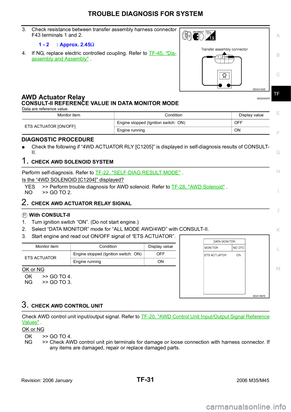
3. Check resistance between transfer assembly harness connector
F43 terminals 1 and 2.
4. If NG, replace electric controlled coupling. Refer to TF-45, "
Dis-
assembly and Assembly" .
AWD Ac tua t or R el a yNDS000DR
CONSULT-II REFERENCE VALUE IN DATA MONITOR MODE
Data are reference value.
DIAGNOSTIC PROCEDURE
Check the following if “4WD ACTUATOR RLY [C1205]” is displayed in self-diagnosis results of CONSULT-
II.
1. CHECK AWD SOLENOID SYSTEM
Perform self-diagnosis. Refer to TF-22, "
SELF-DIAG RESULT MODE" .
Is the
“4WD SOLENOID [C1204]” displayed?
YES >> Perform trouble diagnosis for AWD solenoid. Refer to TF-28, "AWD Solenoid" .
NO >> GO TO 2.
2. CHECK AWD ACTUATOR RELAY SIGNAL
With CONSULT-II
1. Turn ignition switch “ON”. (Do not start engine.)
2. Select “DATA MONITOR” mode for “ALL MODE AWD/4WD” with CONSULT- I I .
3. Start engine and read out ON/OFF signal of “ETS ACTUATOR”.
OK or NG
OK >> GO TO 4.
NG >> GO TO 3.
3. CHECK AWD CONTROL UNIT
Check AWD control unit input/output signal. Refer to TF-20, "
AWD Control Unit Input/Output Signal Reference
Va l u e s" .
OK or NG
OK >> GO TO 4.
NG >> Check AWD control unit pin terminals for damage or loose connection with harness connector. If
any items are damaged, repair or replace damaged parts. 1 - 2 : Approx. 2.45
SDIA2162E
Monitor item Condition Display value
ETS ACTUATOR [ON/OFF]Engine stopped (Ignition switch: ON) OFF
Engine running ON
Monitor item Condition Display value
ETS ACTUATOREngine stopped (Ignition switch: ON) OFF
Engine running ON
SDIA1897E
Page 5589 of 5621

WW-22
FRONT WIPER AND WASHER SYSTEM
Revision: 2006 January2006 M35/M45
Preliminary CheckNKS003WK
CHECK POWER SUPPLY AND GROUND CIRCUIT
1. CHECK FUSE
Check for blown fuses.
Refer to WW-13, "
Wiring Diagram — WIPER —" .
OK or NG
OK >> GO TO 2.
NG >> If fuse or fusible link is blown, be sure to eliminate cause of malfunction before installing new fuse
or fusible link. Refer to PG-3, "
POWER SUPPLY ROUTING CIRCUIT" .
2. CHECK POWER SUPPLY CIRCUIT
1. Turn ignition switch OFF.
2. Disconnect BCM connectors.
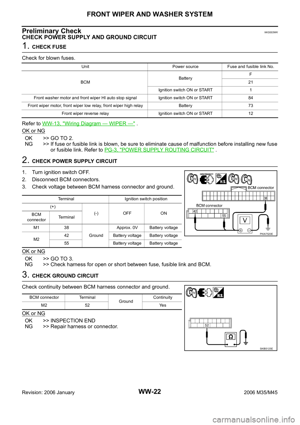
3. Check voltage between BCM harness connector and ground.
OK or NG
OK >> GO TO 3.
NG >> Check harness for open or short between fuse, fusible link and BCM.
3. CHECK GROUND CIRCUIT
Check continuity between BCM harness connector and ground.
OK or NG
OK >> INSPECTION END
NG >> Repair harness or connector.
Unit Power source Fuse and fusible link No.
BCMBatteryF
21
Ignition switch ON or START 1
Front washer motor and front wiper HI auto stop signal Ignition switch ON or START 84
Front wiper motor, front wiper low relay, front wiper high relayBattery 73
Front wiper reverse relay Ignition switch ON or START 12
Terminal Ignition switch position
(+)
(-) OFF ON
BCM
connectorTerminal
M1 38
GroundApprox. 0V Battery voltage
M242 Battery voltage Battery voltage
55 Battery voltage Battery voltage
PKIA7520E
BCM connector Terminal
GroundContinuity
M2 52 Yes
SKIB5125E
Page 5591 of 5621

WW-24
FRONT WIPER AND WASHER SYSTEM
Revision: 2006 January2006 M35/M45
4. Touch “WIPER”.
WORK SUPPORT
Operation Procedure
1. Touch “WIPER” on “SELECT TEST ITEM” screen.
2. Touch “WORK SUPPORT” on “SELECT DIAG MODE” screen.
3. Touch “WIPER SPEED SETTING” on “SELECT WORK ITEM” screen.
4. Touch “START”.
5. Touch “CHANGE SETT”.
6. The setting will be changed and“ CURRENT SETTING” will be displayed.
7. Touch “END”.
Work Support Setting Item
NOTE:
Factory setting
DATA MONITOR
Operation Procedure
1. Touch “WIPER” on the “SELECT TEST ITEM” screen.
2. Touch “DATA MONITOR” on “SELECT DIAG MODE” screen.
3. Touch either “ALL SIGNALS” or “SELECTION FROM MENU” on “SELECT MONITOR ITEM” screen.
4. When “SELECTION FROM MENU” is selected, touch items to be monitored. If “ALL SIGNALS” is
selected, all items will be monitored.
5. Touch “START”.
6. Touch “RECORDING START” while monitoring to record the status of the item being monitored. To stop
recording, touch “RECORDING STOP”.
SKIB4803E
Item Description CONSULT-II
WIPER SPEED SETTINGWhen wiper switch is at INTERMITTENT, front wiper intermittent time can be selected
according to vehicle speed.
ONNOTE (Operated)/OFF (Not operated)ON/OFF
ALL SIGNALS Monitors all the signals.
SELECTION FROM MENU Selects items and monitors them.
Page 5594 of 5621

FRONT WIPER AND WASHER SYSTEM
WW-27
C
D
E
F
G
H
I
J
L
MA
B
WW
Revision: 2006 January2006 M35/M45
4. Select the desired part to be diagnosed on the “SELECT DIAG
MODE” screen.
DATA MONITOR
Operation Procedure
1. Touch “DATA MONITOR” on “SELECT DIAG MODE ” screen.
2. Touch “ALL SIGNALS”, “MAIN SIGNALS” or “SELECTION FROM MENU” on the “SELECT MONITOR
ITEM” screen.
3. When “SELECTION FROM MENU” is selected, touch individual items to be monitored. In “ALL SIG-
NALS”, all items are monitored. In “MAIN SIGNALS”, predetermined items are monitored.
4. Touch “START”.
5. Touch “RECORD” while monitoring to record the status of the item being monitored. To stop recording,
touch “STOP”.
All Signals, Main Signals, Selection From Menu
NOTE:
Perform monitoring of IPDM E/R data with the ignition switch ON. When the ignition switch is at ACC, the dis-
play may not be correct.
ACTIVE TEST
Operation Procedure
1. Touch “ACTIVE TEST” on “SELECT DIAG MODE” screen.
2. Touch “FRONT WIPER” on “SELECT TEST ITEM” screen.
3. Touch item to be tested, and check operation.
4. Touch “OFF” while testing to stop the operation.
BCIA0031E
ALL SIGNALS Monitors all items.
MAIN SIGNALS Monitor the predetermined item.
SELECTION FROM MENU Selects items and monitors them.
Item nameCONSULT-II
screen displayDisplay or unitMonitor item selection
Description
ALL
SIGNALSMAIN
SIGNALSSELECTION
FROM MENU
FR wiper request FR WIP REQSTOP/1 LOW/
LOW/HI
Signal status input from BCM
Wiper auto stop WIP AUTO STOP ACT P/STOP P
Output status of IPDM E/R
Wiper protection WIP PROT OFF/BLOCK
Control status of IPDM E/R
Te s t i t e mCONSULT-II
screen displayDescription
Front wiper (HI, LO) output FRONT WIPERWith a certain operation (HI, LO), the front wiper relay (HIGH and LOW) can be
operated.
Page 5598 of 5621

FRONT WIPER AND WASHER SYSTEM
WW-31
C
D
E
F
G
H
I
J
L
MA
B
WW
Revision: 2006 January2006 M35/M45
7. CHECK IPDM E/R
With CONSULT-II
1. Connect IPDM E/R connector and front wiper motor connector.
2. Install front wiper reverse relay.
3. Select “IPDM E/R” on CONSULT-II. Select “ACTIVE TEST” on “SELECT DIAG MODE” screen.
4. Select “FRONT WIPER” on “SELECT TEST ITEM” screen.
5. Touch “LO” or “HI” screen.
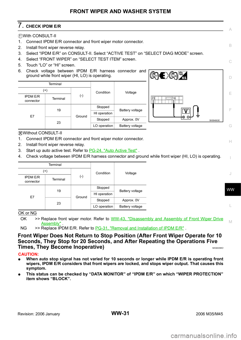
6. Check voltage between IPDM E/R harness connector and
ground while front wiper (HI, LO) is operating.
Without CONSULT-II
1. Connect IPDM E/R connector and front wiper motor connector.
2. Install front wiper reverse relay.
3. Start up auto active test. Refer to PG-24, "
Auto Active Test" .
4. Check voltage between IPDM E/R harness connector and ground while front wiper (HI, LO) is operating.
OK or NG
OK >> Replace front wiper motor. Refer to WW-43, "Disassembly and Assembly of Front Wiper Drive
Assembly" .
NG >> Replace IPDM E/R. Refer to PG-31, "
Removal and Installation of IPDM E/R" .
Front Wiper Does Not Return to Stop Position (After Front Wiper Operate for 10
Seconds, They Stop for 20 Seconds, and After Repeating the Operations Five
Times, They Become Inoperative)
NKS003WO
CAUTION:
When auto stop signal has not varied for 10 seconds or longer while IPDM E/R is operating front
wipers, IPDM E/R considers that front wipers are locked, and stops wiper output. That causes this
symptom.
This status can be checked by “DATA MONITOR” of “IPDM E/R” on which “WIPER PROTECTION”
item shows “BLOCK”.
Terminal
Condition Voltage (+)
(-)
IPDM E/R
connectorTerminal
E719
GroundStopped
Battery voltage
HI operation
23Stopped Approx. 0V
LO operation Battery voltage
Terminal
Condition Voltage (+)
(-)
IPDM E/R
connectorTerminal
E719
GroundStopped
Battery voltage
HI operation
23Stopped Approx. 0V
LO operation Battery voltage
SKIB4663E