Page 4257 of 5621
LAN-588
[CAN]
CAN SYSTEM (TYPE 12)
Revision: 2006 January2006 M35/M45
Case 17
Check CAN communication circuit. Refer to LAN-599, "CAN Communication Circuit Inspection" .
Case 18
Check IPDM E/R ignition relay circuit continuously sticks “OFF”. Refer to LAN-606, "IPDM E/R Ignition Relay
Circuit Inspection" .
PKIB8536E
PKIB8537E
Page 4258 of 5621
CAN SYSTEM (TYPE 12)
LAN-589
[CAN]
C
D
E
F
G
H
I
J
L
MA
B
LAN
Revision: 2006 January2006 M35/M45
Case 19
Check IPDM E/R ignition relay circuit continuously sticks “ON”. Refer to LAN-606, "IPDM E/R Ignition Relay
Circuit Inspection" .
Inspection Between TCM and Data Link Connector CircuitNKS0045H
1. CHECK CONNECTOR
1. Turn ignition switch OFF.
2. Disconnect the battery cable from the negative terminal.
3. Check following terminals and connectors for damage, bend and loose connection (connector side and
harness side).
–Harness connector M61
–Harness connector M62
OK or NG
OK >> GO TO 2.
NG >> Repair terminal or connector.
2. CHECK HARNESS FOR OPEN CIRCUIT
1. Disconnect harness connector M72 and harness connector M61.
2. Check continuity between harness connector (A) and harness
connector (B).
OK or NG
OK >> GO TO 3.
NG >> Repair harness.
PKIB8538E
AB
Continuity
Connector Terminal Connector Terminal
M7243H
M61 1 Yes
42H 2 Yes
PKIC0279E
Page 4275 of 5621
![INFINITI M35 2006 Factory Service Manual LAN-606
[CAN]
CAN SYSTEM (TYPE 12)
Revision: 2006 January2006 M35/M45
19. CHECK SYMPTOM
1. Fill in described symptoms on the column “Symptom” in the check sheet.
2. Connect all connectors, and the](/manual-img/42/57023/w960_57023-4274.png "INFINITI M35 2006 Factory Service Manual LAN-606
[CAN]
CAN SYSTEM (TYPE 12)
Revision: 2006 January2006 M35/M45
19. CHECK SYMPTOM
1. Fill in described symptoms on the column “Symptom” in the check sheet.
2. Connect all connectors, and the")
LAN-606
[CAN]
CAN SYSTEM (TYPE 12)
Revision: 2006 January2006 M35/M45
19. CHECK SYMPTOM
1. Fill in described symptoms on the column “Symptom” in the check sheet.
2. Connect all connectors, and then make sure that the symptom is reproduced.
OK or NG
OK >> GO TO 20.
NG >> Refer to LAN-18, "
Example of Filling in Check Sheet When Initial Conditions Are Not Reproduced"
.
20. CHECK UNIT REPRODUCIBILITY
Performs the following procedure for each unit, and then perform reproducibility test.
1. Turn ignition switch OFF.
2. Disconnect the battery cable from the negative terminal.
3. Disconnect the unit connector.
4. Connect the battery cable to the negative terminal.
5. Make sure that the symptom filled in the “Symptom” of the check sheet is reproduced. (Do not confuse it
with the symptom related to removed unit.)
6. Make sure that the same symptom is reproduced.
–A/T assembly
–AWD control unit
–BCM
–Low tire pressure warning control unit
–Steering angle sensor
–Intelligent Key unit
–Unified meter and A/C amp.
–NAVI control unit
–Driver seat control unit
–ABS actuator and electric unit (control unit)
–ECM
–IPDM E/R
Check results
Reproduce>>Install removed unit, and then check the other unit.
Not reproduced>>Replace removed unit.
IPDM E/R Ignition Relay Circuit InspectionNKS0045Y
Check the following. If no malfunction is found, replace the IPDM E/R.
IPDM E/R power supply circuit. Refer to PG-30, "Check IPDM E/R Power Supply and Ground Circuit" .
Ignition power supply circuit. Refer to PG-12, "IGNITION POWER SUPPLY — IGNITION SW. IN “ON”
AND/OR “START”" .
Page 4304 of 5621
CAN SYSTEM (TYPE 13)
LAN-635
[CAN]
C
D
E
F
G
H
I
J
L
MA
B
LAN
Revision: 2006 January2006 M35/M45
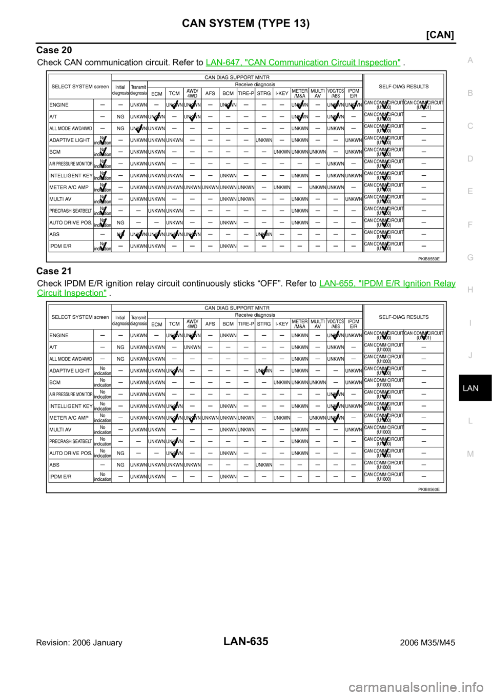
Case 20
Check CAN communication circuit. Refer to LAN-647, "CAN Communication Circuit Inspection" .
Case 21
Check IPDM E/R ignition relay circuit continuously sticks “OFF”. Refer to LAN-655, "IPDM E/R Ignition Relay
Circuit Inspection" .
PKIB8559E
PKIB8560E
Page 4305 of 5621
LAN-636
[CAN]
CAN SYSTEM (TYPE 13)
Revision: 2006 January2006 M35/M45
Case 22
Check IPDM E/R ignition relay circuit continuously sticks “ON”. Refer to LAN-655, "IPDM E/R Ignition Relay
Circuit Inspection" .
Inspection Between TCM and Data Link Connector CircuitNKS00463
1. CHECK CONNECTOR
1. Turn ignition switch OFF.
2. Disconnect the battery cable from the negative terminal.
3. Check following terminals and connectors for damage, bend and loose connection (connector side and
harness side).
–Harness connector M61
–Harness connector M62
OK or NG
OK >> GO TO 2.
NG >> Repair terminal or connector.
2. CHECK HARNESS FOR OPEN CIRCUIT
1. Disconnect harness connector M72 and harness connector M61.
2. Check continuity between harness connector (A) and harness
connector (B).
OK or NG
OK >> GO TO 3.
NG >> Repair harness.
PKIB8561E
AB
Continuity
Connector Terminal Connector Terminal
M7243H
M61 1 Yes
42H 2 Yes
PKIC0279E
Page 4324 of 5621
CAN SYSTEM (TYPE 13)
LAN-655
[CAN]
C
D
E
F
G
H
I
J
L
MA
B
LAN
Revision: 2006 January2006 M35/M45
IPDM E/R Ignition Relay Circuit InspectionNKS0046N
Check the following. If no malfunction is found, replace the IPDM E/R.
IPDM E/R power supply circuit. Refer to PG-30, "Check IPDM E/R Power Supply and Ground Circuit" .
Ignition power supply circuit. Refer to PG-12, "IGNITION POWER SUPPLY — IGNITION SW. IN “ON”
AND/OR “START”" .
Page 4353 of 5621
LAN-684
[CAN]
CAN SYSTEM (TYPE 14)
Revision: 2006 January2006 M35/M45
Case 20
Check CAN communication circuit. Refer to LAN-696, "CAN Communication Circuit Inspection" .
Case 21
Check IPDM E/R ignition relay circuit continuously sticks “OFF”. Refer to LAN-704, "IPDM E/R Ignition Relay
Circuit Inspection" .
PKIB8559E
PKIB8560E
Page 4354 of 5621
CAN SYSTEM (TYPE 14)
LAN-685
[CAN]
C
D
E
F
G
H
I
J
L
MA
B
LAN
Revision: 2006 January2006 M35/M45
Case 22
Check IPDM E/R ignition relay circuit continuously sticks “ON”. Refer to LAN-704, "IPDM E/R Ignition Relay
Circuit Inspection" .
Inspection Between TCM and Data Link Connector CircuitNKS0046S
1. CHECK CONNECTOR
1. Turn ignition switch OFF.
2. Disconnect the battery cable from the negative terminal.
3. Check following terminals and connectors for damage, bend and loose connection (connector side and
harness side).
–Harness connector M61
–Harness connector M62
OK or NG
OK >> GO TO 2.
NG >> Repair terminal or connector.
2. CHECK HARNESS FOR OPEN CIRCUIT
1. Disconnect harness connector M72 and harness connector M61.
2. Check continuity between harness connector (A) and harness
connector (B).
OK or NG
OK >> GO TO 3.
NG >> Repair harness.
PKIB8561E
AB
Continuity
Connector Terminal Connector Terminal
M7243H
M61 1 Yes
42H 2 Yes
PKIC0279E
![INFINITI M35 2006 Factory Service Manual LAN-588
[CAN]
CAN SYSTEM (TYPE 12)
Revision: 2006 January2006 M35/M45
Case 17
Check CAN communication circuit. Refer to LAN-599, "CAN Communication Circuit Inspection" .
Case 18
Check IPDM E/R](/manual-img/42/57023/w960_57023-4256.png "INFINITI M35 2006 Factory Service Manual LAN-588
[CAN]
CAN SYSTEM (TYPE 12)
Revision: 2006 January2006 M35/M45
Case 17
Check CAN communication circuit. Refer to LAN-599, \"CAN Communication Circuit Inspection\" .
Case 18
Check IPDM E/R")
![INFINITI M35 2006 Factory Service Manual CAN SYSTEM (TYPE 12)
LAN-589
[CAN]
C
D
E
F
G
H
I
J
L
MA
B
LAN
Revision: 2006 January2006 M35/M45
Case 19
Check IPDM E/R ignition relay circuit continuously sticks “ON”. Refer to LAN-606,](/manual-img/42/57023/w960_57023-4257.png "INFINITI M35 2006 Factory Service Manual CAN SYSTEM (TYPE 12)
LAN-589
[CAN]
C
D
E
F
G
H
I
J
L
MA
B
LAN
Revision: 2006 January2006 M35/M45
Case 19
Check IPDM E/R ignition relay circuit continuously sticks “ON”. Refer to LAN-606,")
![INFINITI M35 2006 Factory Service Manual LAN-636
[CAN]
CAN SYSTEM (TYPE 13)
Revision: 2006 January2006 M35/M45
Case 22
Check IPDM E/R ignition relay circuit continuously sticks “ON”. Refer to LAN-655, "IPDM E/R Ignition](/manual-img/42/57023/w960_57023-4304.png "INFINITI M35 2006 Factory Service Manual LAN-636
[CAN]
CAN SYSTEM (TYPE 13)
Revision: 2006 January2006 M35/M45
Case 22
Check IPDM E/R ignition relay circuit continuously sticks “ON”. Refer to LAN-655, \"IPDM E/R Ignition")
![INFINITI M35 2006 Factory Service Manual CAN SYSTEM (TYPE 13)
LAN-655
[CAN]
C
D
E
F
G
H
I
J
L
MA
B
LAN
Revision: 2006 January2006 M35/M45
IPDM E/R Ignition Relay Circuit InspectionNKS0046N
Check the following. If no malfunction is found, rep](/manual-img/42/57023/w960_57023-4323.png "INFINITI M35 2006 Factory Service Manual CAN SYSTEM (TYPE 13)
LAN-655
[CAN]
C
D
E
F
G
H
I
J
L
MA
B
LAN
Revision: 2006 January2006 M35/M45
IPDM E/R Ignition Relay Circuit InspectionNKS0046N
Check the following. If no malfunction is found, rep")
![INFINITI M35 2006 Factory Service Manual LAN-684
[CAN]
CAN SYSTEM (TYPE 14)
Revision: 2006 January2006 M35/M45
Case 20
Check CAN communication circuit. Refer to LAN-696, "CAN Communication Circuit Inspection" .
Case 21
Check IPDM E/R](/manual-img/42/57023/w960_57023-4352.png "INFINITI M35 2006 Factory Service Manual LAN-684
[CAN]
CAN SYSTEM (TYPE 14)
Revision: 2006 January2006 M35/M45
Case 20
Check CAN communication circuit. Refer to LAN-696, \"CAN Communication Circuit Inspection\" .
Case 21
Check IPDM E/R")
![INFINITI M35 2006 Factory Service Manual CAN SYSTEM (TYPE 14)
LAN-685
[CAN]
C
D
E
F
G
H
I
J
L
MA
B
LAN
Revision: 2006 January2006 M35/M45
Case 22
Check IPDM E/R ignition relay circuit continuously sticks “ON”. Refer to LAN-704,](/manual-img/42/57023/w960_57023-4353.png "INFINITI M35 2006 Factory Service Manual CAN SYSTEM (TYPE 14)
LAN-685
[CAN]
C
D
E
F
G
H
I
J
L
MA
B
LAN
Revision: 2006 January2006 M35/M45
Case 22
Check IPDM E/R ignition relay circuit continuously sticks “ON”. Refer to LAN-704,")