Page 4509 of 5621

LT-82
HEADLAMP (FOR CANADA) - DAYTIME LIGHT SYSTEM -
Revision: 2006 January2006 M35/M45
DAYTIME LIGHT OPERATION
With the engine running, the lighting switch in the OFF or AUTO position (headlamp is not illuminate) and
parking brake released, the IPDM E/R receives input request signal from BCM to turn on daytime light. This
input is communicated across the CAN communication lines. The CPU of the IPDM E/R controls the daytime
light relay coil. When energized, this relay directs power
through daytime light relay terminals 5 and 3
through front combination lamp RH terminal 2
through front combination lamp RH terminal 6
through IPDM E/R terminal 27
through 10A fuse (No. 72, located in IPDM E/R)
through 10A fuse (No. 74, located in IPDM E/R)
through IPDM E/R terminal 28
to front combination lamp LH terminal 6.
Ground is supplied
to combination lamp LH terminal 2
through grounds E22 and E43.
With power and grounds supplied, the daytime lights illuminate. The high beam headlamps are now wired in
series and illuminate at a reduced intensity.
COMBINATION SWITCH READING FUNCTION
Refer to BCS-3, "COMBINATION SWITCH READING FUNCTION" .
AUTO LIGHT OPERATION
For auto light operation, refer to LT- 11 6 , "System Description" .
CAN Communication System DescriptionNKS003PB
Refer to LAN-34, "CAN COMMUNICATION" .
Page 4518 of 5621

HEADLAMP (FOR CANADA) - DAYTIME LIGHT SYSTEM -
LT-91
C
D
E
F
G
H
I
J
L
MA
B
LT
Revision: 2006 January2006 M35/M45
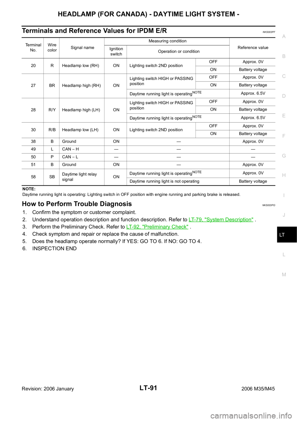
Terminals and Reference Values for IPDM E/RNKS003PF
NOTE:
Daytime running light is operating: Lighting switch in OFF position with engine running and parking brake is released.
How to Perform Trouble DiagnosisNKS003PG
1. Confirm the symptom or customer complaint.
2. Understand operation description and function description. Refer to LT- 7 9 , "
System Description" .
3. Perform the Preliminary Check. Refer to LT-92, "
Preliminary Check" .
4. Check symptom and repair or replace the cause of malfunction.
5. Does the headlamp operate normally? If YES: GO TO 6. If NO: GO TO 4.
6. INSPECTION END
Terminal
No.Wire
colorSignal nameMeasuring condition
Reference value
Ignition
switchOperation or condition
20 R Headlamp low (RH) ON Lighting switch 2ND positionOFF Approx. 0V
ON Battery voltage
27 BR Headlamp high (RH) ONLighting switch HIGH or PASSING
positionOFF Approx. 0V
ON Battery voltage
Daytime running light is operating
NOTEApprox. 6.5V
28 R/Y Headlamp high (LH) ONLighting switch HIGH or PASSING
positionOFF Approx. 0V
ON Battery voltage
Daytime running light is operating
NOTEApprox. 6.5V
30 R/B Headlamp low (LH) ON Lighting switch 2ND positionOFF Approx. 0V
ON Battery voltage
38 B Ground ON — Approx. 0V
49 L CAN
H — — —
50 P CAN
L — — —
51 B Ground ON — Approx. 0V
58 SBDaytime light relay
signalONDaytime running light is operating
NOTEApprox. 0V
Daytime running light is not operating Battery voltage
Page 4519 of 5621

LT-92
HEADLAMP (FOR CANADA) - DAYTIME LIGHT SYSTEM -
Revision: 2006 January2006 M35/M45
Preliminary CheckNKS003PH
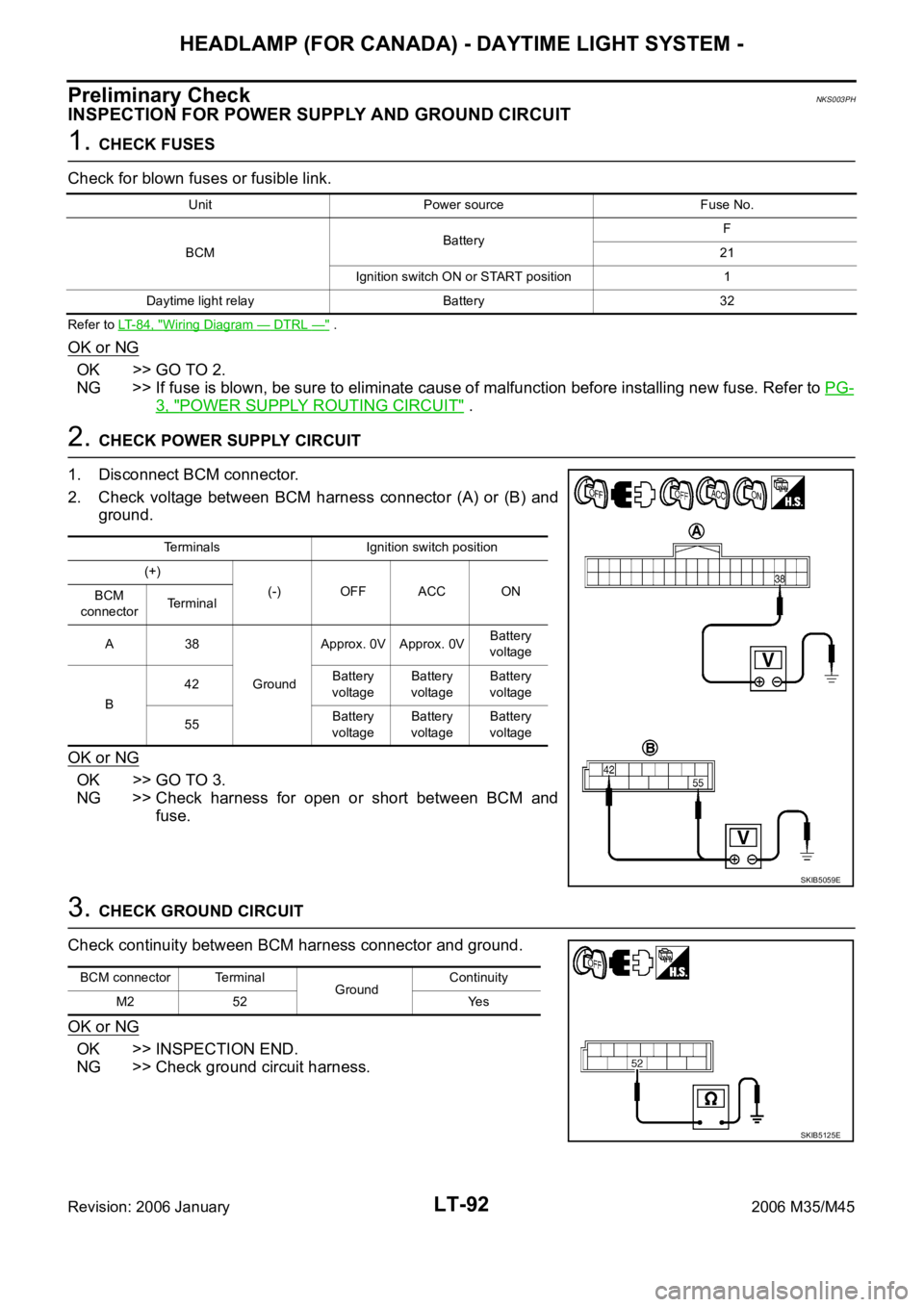
INSPECTION FOR POWER SUPPLY AND GROUND CIRCUIT
1. CHECK FUSES
Check for blown fuses or fusible link.
Refer to LT-84, "Wiring Diagram — DTRL —" .
OK or NG
OK >> GO TO 2.
NG >> If fuse is blown, be sure to eliminate cause of malfunction before installing new fuse. Refer to PG-
3, "POWER SUPPLY ROUTING CIRCUIT" .
2. CHECK POWER SUPPLY CIRCUIT
1. Disconnect BCM connector.
2. Check voltage between BCM harness connector (A) or (B) and
ground.
OK or NG
OK >> GO TO 3.
NG >> Check harness for open or short between BCM and
fuse.
3. CHECK GROUND CIRCUIT
Check continuity between BCM harness connector and ground.
OK or NG
OK >> INSPECTION END.
NG >> Check ground circuit harness.
Unit Power source Fuse No.
BCMBatteryF
21
Ignition switch ON or START position 1
Daytime light relay Battery 32
Terminals Ignition switch position
(+)
(-) OFF ACC ON
BCM
connectorTerminal
A38
GroundApprox. 0V Approx. 0VBattery
voltage
B42Battery
voltageBattery
voltageBattery
voltage
55Battery
voltageBattery
voltageBattery
voltage
SKIB5059E
BCM connector Terminal
GroundContinuity
M2 52 Yes
SKIB5125E
Page 4523 of 5621

LT-96
HEADLAMP (FOR CANADA) - DAYTIME LIGHT SYSTEM -
Revision: 2006 January2006 M35/M45
NOTE:
This item is displayed, but cannot be monitored.
ACTIVE TEST
Operation Procedure
1. Touch “HEAD LAMP” on “SELECT TEST ITEM” screen.
2. Touch “ACTIVE TEST” on “SELECT DIAG MODE” screen.
3. Touch item to be tested and check operation of the selected item.
4. During the operation check, touching “BACK” deactivates the operation.
Display Item List
DOOR SW - RL “ON/OFF”Displays status of the rear door as judged from the rear door switch (LH) signal. (door is open:
ON/door is closed: OFF)
BACK DOOR SW
NOTE “OFF” —
PKB SW “ON/OFF”Displays status (parking brake released: ON/ parking brake applied: OFF) of parking brake
switch judged from parking brake switch signal.
ENGINE RUN “ON/OFF”Displays status (engine running: ON/ engine stopped: OFF) of engine judged from engine run
signal.
OPTICAL SENSOR “0 - 5V” Displays “outside brightness (close to 5V when light/close to 0V when dark)” judged from opti-
cal sensor signal.
VEHICLE SPEED “km/h” Displays vehicle speed as judged from vehicle speed signal. Monitor item Contents
Test item Description
TAIL LAMP Allows tail lamp relay to operate by switching ON-OFF.
FR FOG LAMP Allows front fog lamp relay to operate by switching ON-OFF.
DAYTIME RUNNING LIGHT Allows daytime relay to operate by switching ON-OFF.
HEAD LAMP (HI, LO) Allows headlamp relay to operate by switching ON-OFF.
Page 4525 of 5621

LT-98
HEADLAMP (FOR CANADA) - DAYTIME LIGHT SYSTEM -
Revision: 2006 January2006 M35/M45
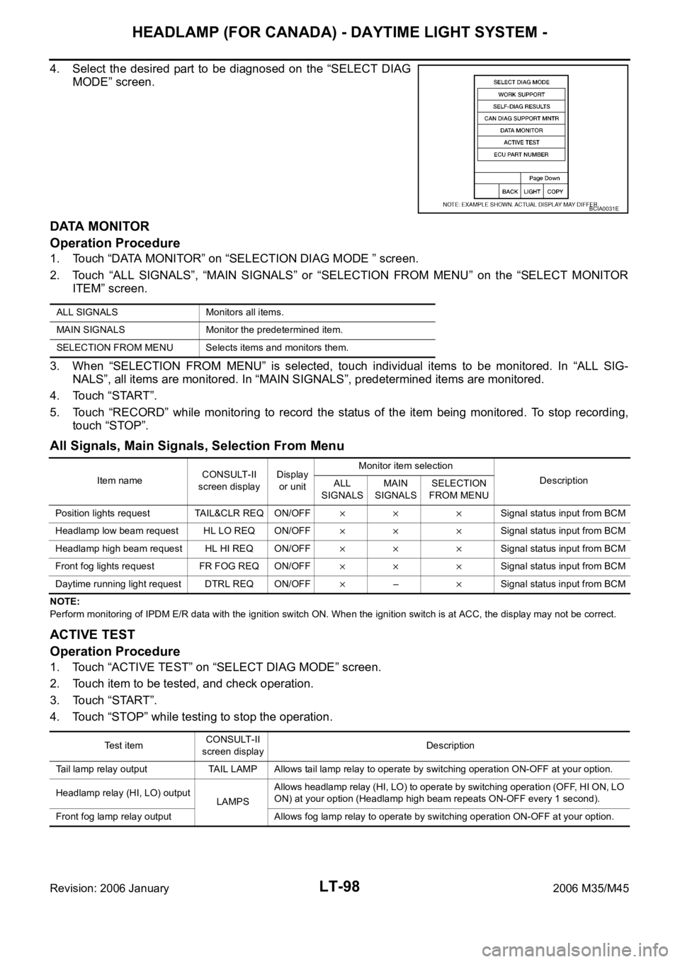
4. Select the desired part to be diagnosed on the “SELECT DIAG
MODE” screen.
DATA MONITOR
Operation Procedure
1. Touch “DATA MONITOR” on “SELECTION DIAG MODE ” screen.
2. Touch “ALL SIGNALS”, “MAIN SIGNALS” or “SELECTION FROM MENU” on the “SELECT MONITOR
ITEM” screen.
3. When “SELECTION FROM MENU” is selected, touch individual items to be monitored. In “ALL SIG-
NALS”, all items are monitored. In “MAIN SIGNALS”, predetermined items are monitored.
4. Touch “START”.
5. Touch “RECORD” while monitoring to record the status of the item being monitored. To stop recording,
touch “STOP”.
All Signals, Main Signals, Selection From Menu
NOTE:
Perform monitoring of IPDM E/R data with the ignition switch ON. When the ignition switch is at ACC, the display may not be correct.
ACTIVE TEST
Operation Procedure
1. Touch “ACTIVE TEST” on “SELECT DIAG MODE” screen.
2. Touch item to be tested, and check operation.
3. Touch “START”.
4. Touch “STOP” while testing to stop the operation.
BCIA0031E
ALL SIGNALS Monitors all items.
MAIN SIGNALS Monitor the predetermined item.
SELECTION FROM MENU Selects items and monitors them.
Item nameCONSULT-II
screen displayDisplay
or unitMonitor item selection
Description
ALL
SIGNALSMAIN
SIGNALSSELECTION
FROM MENU
Position lights request TAIL&CLR REQ ON/OFF
Signal status input from BCM
Headlamp low beam request HL LO REQ ON/OFF
Signal status input from BCM
Headlamp high beam request HL HI REQ ON/OFF
Signal status input from BCM
Front fog lights request FR FOG REQ ON/OFF
Signal status input from BCM
Daytime running light request DTRL REQ ON/OFF
–Signal status input from BCM
Test itemCONSULT-II
screen displayDescription
Tail lamp relay output TAIL LAMP Allows tail lamp relay to operate by switching operation ON-OFF at your option.
Headlamp relay (HI, LO) output
LAMPSAllows headlamp relay (HI, LO) to operate by switching operation (OFF, HI ON, LO
ON) at your option (Headlamp high beam repeats ON-OFF every 1 second).
Front fog lamp relay output Allows fog lamp relay to operate by switching operation ON-OFF at your option.
Page 4527 of 5621
LT-100
HEADLAMP (FOR CANADA) - DAYTIME LIGHT SYSTEM -
Revision: 2006 January2006 M35/M45
4. CHECK DAYTIME LIGHT RELAY POWER SUPPLY CIRCUIT
1. Turn ignition switch OFF.
2. Remove daytime light relay.
3. Check voltage between daytime light relay harness connector
E34 terminals 2, 5 and ground.
OK or NG
OK >> GO TO 5.
NG >> Repair harness or connector.
5. CHECK DAYTIME LIGHT RELAY
1. Apply battery voltage to daytime light relay terminals 1 and 2.
2. Check continuity between terminals 3 and 5.
OK or NG
OK >> GO TO 6.
NG >> Replace daytime light relay.
6. CHECK CIRCUIT BETWEEN DAYTIME LIGHT RELAY AND IPDM E/R
1. Disconnect IPDM E/R connector.
2. Check continuity between IPDM E/R harness connector (A) E9
terminal 58 and daytime light relay harness connector (B) E34
terminal 1.
OK or NG
OK >> GO TO 7.
NG >> Repair harness or connector.2, 5 – Ground : Battery voltage
SKIB4746E
3 – 5 : Continuity should exist.
SKIB4671E
58 – 1 : Continuity should exist.
SKIB4748E
Page 4528 of 5621

HEADLAMP (FOR CANADA) - DAYTIME LIGHT SYSTEM -
LT-101
C
D
E
F
G
H
I
J
L
MA
B
LT
Revision: 2006 January2006 M35/M45
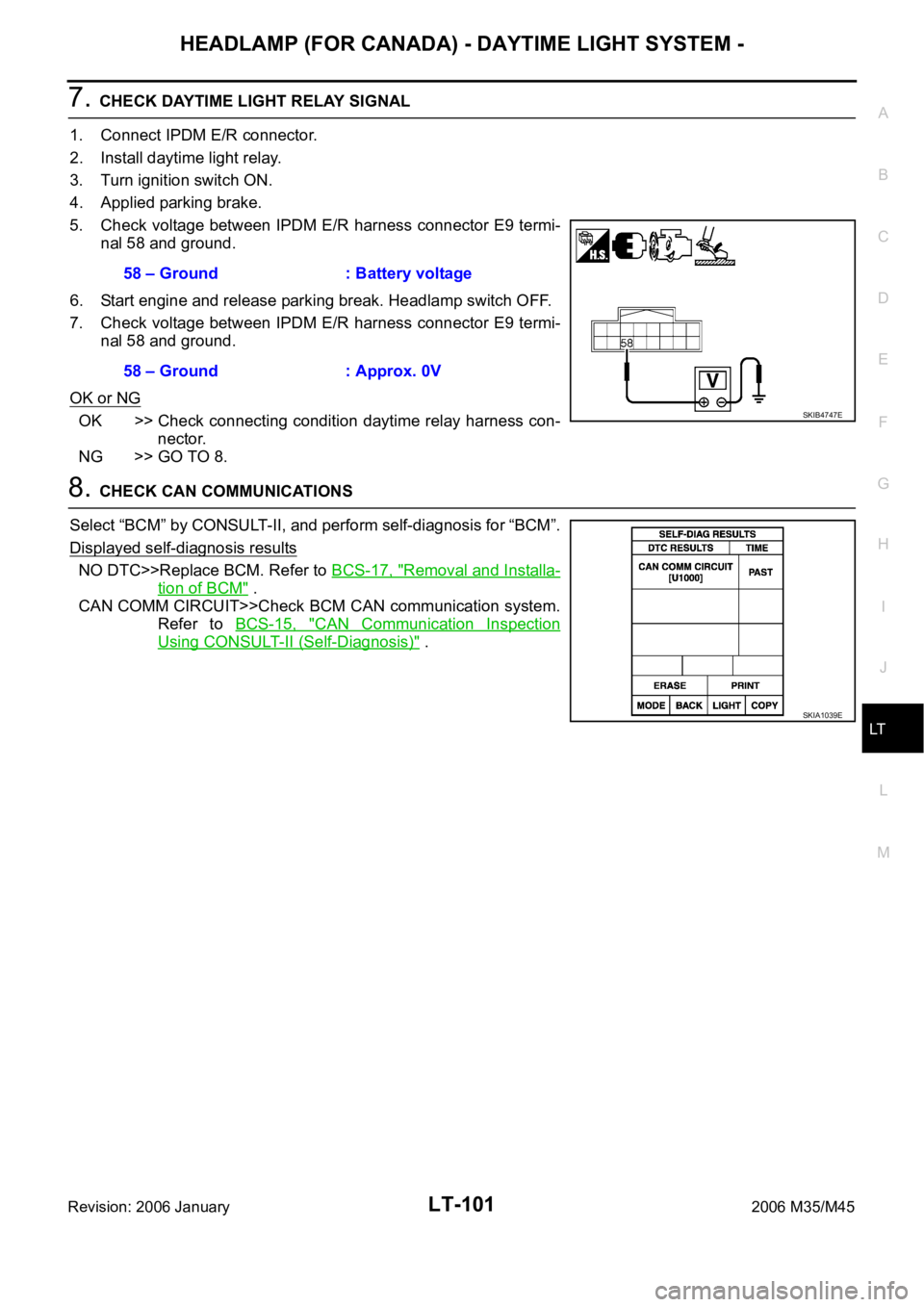
7. CHECK DAYTIME LIGHT RELAY SIGNAL
1. Connect IPDM E/R connector.
2. Install daytime light relay.
3. Turn ignition switch ON.
4. Applied parking brake.
5. Check voltage between IPDM E/R harness connector E9 termi-
nal 58 and ground.
6. Start engine and release parking break. Headlamp switch OFF.
7. Check voltage between IPDM E/R harness connector E9 termi-
nal 58 and ground.
OK or NG
OK >> Check connecting condition daytime relay harness con-
nector.
NG >> GO TO 8.
8. CHECK CAN COMMUNICATIONS
Select “BCM” by CONSULT-II, and perform self-diagnosis for “BCM”.
Displayed self-diagnosis results
NO DTC>>Replace BCM. Refer to BCS-17, "Removal and Installa-
tion of BCM" .
CAN COMM CIRCUIT>>Check BCM CAN communication system.
Refer to BCS-15, "
CAN Communication Inspection
Using CONSULT-II (Self-Diagnosis)" . 58 – Ground : Battery voltage
58 – Ground : Approx. 0V
SKIB4747E
SKIA1039E
Page 4531 of 5621
LT-104
HEADLAMP (FOR CANADA) - DAYTIME LIGHT SYSTEM -
Revision: 2006 January2006 M35/M45
6. CHECK HEADLAMP (RH SIDE) GROUND
1. Remove daytime light relay.
2. Check continuity between front headlamp RH harness connec-
tor (A) E47 terminal 2 and daytime light relay harness connector
(B) E34 terminal 3.
3. Check continuity between daytime light relay harness connector
E34 terminal 4 and ground.
OK or NG
OK >> GO TO 7.
NG >> Repair harness or connector.
7. CHECK DAYTIME LIGHT RELAY
Check continuity between terminal 3 and 4.
OK >> Check headlamp bulb and connecting condition combi-
nation lamp terminal connector.
NG >> Replace daytime light relay.2 – 3 : Continuity should exist.
SKIB4751E
4 – Ground : Continuity should exist.
SKIB4674E
3 – 4 : Continuity should exist.
SKIB4660E