Page 4937 of 5621
PG-110
STANDARDIZED RELAY
Revision: 2006 January2006 M35/M45
SEL188W
Page 4939 of 5621
PG-112
FUSE, FUSIBLE LINK AND RELAY BOX
Revision: 2006 January2006 M35/M45
FUSE, FUSIBLE LINK AND RELAY BOXPFP:24382
Terminal ArrangementNKS004F0
CKIT0664E
Page 5102 of 5621
PRE-CRASH SEAT BELT
SB-3
C
D
E
F
G
I
J
K
L
MA
B
SB
Revision: 2006 January2006 M35/M45
PRE-CRASH SEAT BELTPFP:98845
Component Parts and Harness Connector LocationNHS0007X
System DescriptionNHS0007Y
Pre-crash seat belt system is adapted to front seat belts RH/LH.
When the pre-crash seat belt control unit judges the emergency braking operation, it gives the sense of
security by the motor built into the pre-crash seat belt retracting the shoulder belt and suppressing the
crew's posture change. Also, it eases the damage of the collision.
PHIA1123E
1. Fuse block (J/B) 2.Fuse, fusible link and relay block
(J/B)3.Pre-crash seat belt control unit B142
(View with the trunk side finisher LH
removed)
4.Brake pedal stroke sensor E125
(View with the instrument driver
lower panel removed)5.Pre-crash seat belt motor B32 (LH),
B8 (RH)
(View with the center pillar lower
garnish removed)6.Seat belt buckle switch B203 (driver
seat) B253 (passenger seat)
Page 5146 of 5621
BATTERY
SC-9
C
D
E
F
G
H
I
J
L
MA
B
SC
Revision: 2006 January2006 M35/M45
Removal and Installation NKS003NH
REMOVAL
1. Remove engine room cover RH.
2. Remove battery cover.
3. Remove the clips (A), and remove hoodledge cover RH (1).
4. Loosen battery terminal nuts (1), and disconnect both battery
cables from battery terminals.
CAUTION:
When disconnecting, disconnect the battery cable from the
negative terminal first.
5. Remove battery fix frame mounting nuts (2) and battery fix
frame.
6. Remove relay box (3) from the bracket.
7. Remove battery.
INSTALLATION
Installation is the reverse order of removal.
CAUTION:
When connecting, connect the battery cable to the positive terminal first.
PKIB8791E
PKIB8792E
Battery fix frame mounting nut
: 4.4 Nꞏm (0.45 kg-m, 39 in-lb)
Battery terminal nut
: 5.4 Nꞏm (0.55 kg-m, 48 in-lb)
Page 5147 of 5621
SC-10
STARTING SYSTEM
Revision: 2006 January2006 M35/M45
STARTING SYSTEM PFP:00011
System Description NKS003NI
Power is supplied at all times
through 15A fuse (No. 78, located in the IPDM E/R)
to CPU of IPDM E/R,
through 15A fuse (No. 71, located in the IPDM E/R)
to CPU of IPDM E/R.
Ground is supplied
to IPDM E/R terminals 38 and 51
from grounds E22 and E43.
When the selector lever in the P or N position, power is supplied
from TCM, and through A/T assembly terminal 9
to IPDM E/R terminal 53.
And then provided that IPDM E/R receives a starter relay ON signal with CAN communication, starter relay is
energized.
With the ignition switch in the START position, power is supplied
through IPDM E/R terminal 3
to starter motor terminal 1.
The starter motor plunger closes and provides a closed circuit between the battery and starter motor. The
starter motor is grounded to the engine block. With power and ground supplied, cranking occurs and the
engine starts.
Page 5160 of 5621

CHARGING SYSTEM
SC-23
C
D
E
F
G
H
I
J
L
MA
B
SC
Revision: 2006 January2006 M35/M45
CHARGING SYSTEM PFP:00011
System Description NKS003NN
DESCRIPTION
The alternator provides DC voltage to operate the vehicle's electrical system and to keep the battery charged.
The voltage output is controlled by the IC regulator.
Power is supplied at all times
through 10A fuse [No. 36, located in the fuse, fusible link and relay block (J/B)]
to alternator terminal 4 (“S” terminal).
“B” terminal supplies power to charge the battery and operate the vehicle's electrical system. Output voltage is
controlled by the IC regulator at terminal 4 (“S” terminal) detecting the input voltage.
The alternator is grounded to the engine block.
With the ignition switch in the ON or START position, power is supplied
through 10A fuse [No. 14, located in the fuse block (J/B)]
to combination meter terminal 12 for the charge warning lamp.
Ground is supplied at signal
to combination meter terminal 22
through alternator terminal 3 (“L” terminal).
Then power and ground are supplied, the charge warning lamp will illuminate.
When the alternator is providing sufficient voltage with the engine running, the ground is opened and the
charge warning lamp will go off.
If the charge warning lamp illuminates with the engine running, a malfunction is indicated.
Ground is supplied
to alternator terminal 2 (“E” terminal)
through grounds E222, E223 and E224. (VQ35DE)
through ground E212. (VK45DE)
MALFUNCTION INDICATOR
The IC regulator warning function activates to illuminate the charge warning lamp, if any of the following symp-
toms occur while alternator is operating:
Excessive voltage is produced.
No voltage is produced.
Page 5272 of 5621
POWER SEAT(PASSENGER SIDE)
SE-91
C
D
E
F
G
H
J
K
L
MA
B
SE
Revision: 2006 January2006 M35/M45
POWER SEAT(PASSENGER SIDE)PFP:87050
Component Parts and Harness Connector LocationNIS0026Z
PIIB5888E
1. Fuse block (J/B) 2.Fuse, fusible link and relay block (J/
B)3.BCM M2
(View with the glove box cover
removed)
4.Power seat switch B255
a: Reclining switch
b: Sliding and lifting switch5.a: Sliding motor M264
b: Lifting motor M2666. Reclining motor M263
Page 5276 of 5621

POWER SEAT(REAR)
SE-95
C
D
E
F
G
H
J
K
L
MA
B
SE
Revision: 2006 January2006 M35/M45
POWER SEAT(REAR)PFP:88010
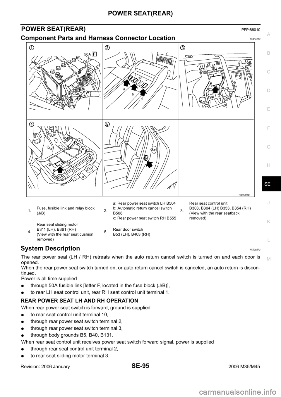
Component Parts and Harness Connector LocationNIS00272
System DescriptionNIS00273
The rear power seat (LH / RH) retreats when the auto return cancel switch is turned on and each door is
opened.
When the rear power seat switch turned on, or auto return cancel switch is canceled, an auto return is discon-
tinued.
Power is all time supplied
through 50A fusible link [letter F, located in the fuse block (J/B)],
to rear LH seat control unit, rear RH seat control unit terminal 1.
REAR POWER SEAT LH AND RH OPERATION
When rear power seat switch is forward, ground is supplied
to rear seat control unit terminal 10,
through rear power seat switch terminal 2,
through rear power seat switch terminal 3,
through body grounds B5, B40, B131.
When rear seat control unit receives power seat switch forward signal, power is supplied
through rear seat control unit terminal 2,
to rear seat sliding motor terminal 3.
PIIB5889E
1.Fuse, fusible link and relay block
(J/B)2.a: Rear power seat switch LH B504
b: Automatic return cancel switch
B508
c: Rear power seat switch RH B5553.Rear seat control unit
B303, B304 (LH) B353, B354 (RH)
(View with the rear seatback
removed)
4.Rear seat sliding motor
B311 (LH), B361 (RH)
(View with the rear seat cushion
removed)5.Rear door switch
B53 (LH), B403 (RH)