2006 INFINITI M35 seat memory
[x] Cancel search: seat memoryPage 5218 of 5621
![INFINITI M35 2006 Factory Service Manual AUTOMATIC DRIVE POSITIONER
SE-37
C
D
E
F
G
H
J
K
L
MA
B
SE
Revision: 2006 January2006 M35/M45
DATA MONITOR
SELECTIOM FROM MEMU
SEAT LIFTER FR
[B2114]Seat lifting FR motorWhen any manual and automatic INFINITI M35 2006 Factory Service Manual AUTOMATIC DRIVE POSITIONER
SE-37
C
D
E
F
G
H
J
K
L
MA
B
SE
Revision: 2006 January2006 M35/M45
DATA MONITOR
SELECTIOM FROM MEMU
SEAT LIFTER FR
[B2114]Seat lifting FR motorWhen any manual and automatic](/manual-img/42/57023/w960_57023-5217.png)
AUTOMATIC DRIVE POSITIONER
SE-37
C
D
E
F
G
H
J
K
L
MA
B
SE
Revision: 2006 January2006 M35/M45
DATA MONITOR
SELECTIOM FROM MEMU
SEAT LIFTER FR
[B2114]Seat lifting FR motorWhen any manual and automatic operations are not performed, if
any motor operations of seat lifting FR is detected for 0.1 second or
more, status is judged “Output error”.SE-46
SE-56
SEAT LIFTER RR
[B2115]Seat lifting RR motorWhen any manual and automatic operations are not performed, if
any motor operations of seat lifting RR is detected for 0.1 second or
more, status is judged “Output error”.SE-48
SE-58
TILT OUTPUT
[B2116]Tilt motorWhen any manual and automatic operations are not performed, if
any motor operations of seat tilt is detected for 0.1 second or more,
status is judged “Output error”.SE-50
TILT SENSOR
[B2118]Tilt sensorWhen driver seat control unit detects 0.1V or lower, or 4.9V or higher,
from tilt sensor for 0.5 seconds or more.SE-62
TELESCO SEN-
SOR
[B2119]Telescopic sensorWhen driver seat control unit detects 0.1V or lower, or 4.9V or higher,
from telescopic sensor for 0.5 seconds or more.SE-60
DETENT SW
[B2126]Detention SWWith the A/T selector lever in P position (Detente switch OFF), if the
vehicle speed of 7 km/h (4 MPH) or higher was input the detention
switch input system is judged malfunctioning.SE-85
UART COMM
[B2128]UART communica-
tionMalfunction is detected in UART communication.SE-87
CONSULT-II display Item Malfunction is detected when...Reference
page
Monitor item [OPERATION or UNIT] Contents
SET SW “ON/OFF” ON/OFF status judged from the setting switch signal is displayed.
MEMORY SW1 “ON/OFF” ON/OFF status judged from the seat memory switch 1 signal is displayed.
MEMORY SW2 “ON/OFF” ON/OFF status judged from the seat memory switch 2 signal is displayed.
SLIDE SW–FR “ON/OFF” ON/OFF status judged from the sliding switch (FR) signal is displayed.
SLIDE SW–RR “ON/OFF” ON/OFF status judged from the sliding switch (RR) signal is displayed.
RECLN SW–FR “ON/OFF” ON/OFF status judged from the reclining switch (FR) signal is displayed.
RECLN SW–RR “ON/OFF” ON/OFF status judged from the reclining switch (RR) signal is displayed.
LIFT FR SW–UP “ON/OFF” ON/OFF status judged from the FR lifting switch (UP) signal is displayed.
LIFT FR SW–DN “ON/OFF” ON/OFF status judged from the FR lifting switch (DOWN) signal is displayed.
LIFT RR SW–UP “ON/OFF” ON/OFF status judged from the RR lifting switch (UP) signal is displayed.
LIFT RR SW–DN “ON/OFF” ON/OFF status judged from the RR lifting switch (DOWN) signal is displayed.
MIR CON SW–UP “ON/OFF”ON/OFF status judged from the door mirror remote control switch (UP) signal is
displayed.
MIR CON SW–DN “ON/OFF”ON/OFF status judged from the door mirror remote control switch (DOWN) signal
is displayed.
MIR CON SW–RH “ON/OFF”ON/OFF status judged from the door mirror remote control switch (RIGHT) signal
is displayed.
MIR CON SW–LH “ON/OFF”ON/OFF status judged from the door mirror remote control switch (LEFT) signal is
displayed.
MIR CHNG SW–R “ON/OFF”ON/OFF status judged from the door mirror remote control switch (switching to
RIGHT) signal is displayed.
MIR CHNG SW–L “ON/OFF”ON/OFF status judged from the door mirror remote control switch (switching to
LEFT) signal is displayed.
TILT SW-UP “ON/OFF” ON/OFF status judged from the tilt switch (UP) signal is displayed.
TILT SW-DOWN “ON/OFF” ON/OFF status judged from the tilt switch (DOWN) signal is displayed.
TELESCO SW-FR “ON/OFF” ON/OFF status judged from the telescoping switch (FR) signal is displayed.
TELESCO SW-RR “ON/OFF” ON/OFF status judged from the telescoping switch (RR) signal is displayed.
Page 5219 of 5621
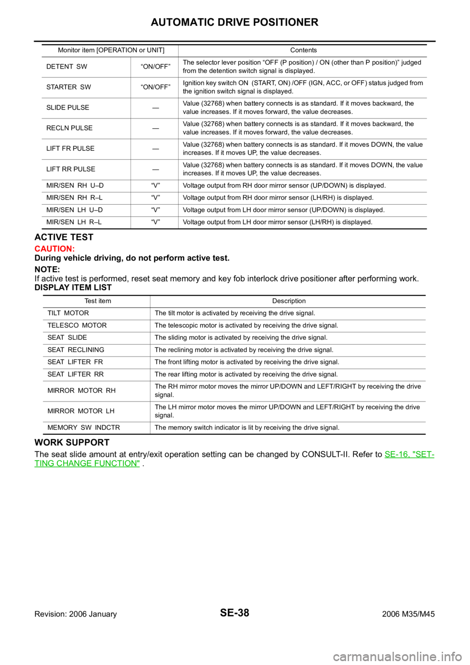
SE-38
AUTOMATIC DRIVE POSITIONER
Revision: 2006 January2006 M35/M45
ACTIVE TEST
CAUTION:
During vehicle driving, do not perform active test.
NOTE:
If active test is performed, reset seat memory and key fob interlock drive positioner after performing work.
DISPLAY ITEM LIST
WORK SUPPORT
The seat slide amount at entry/exit operation setting can be changed by CONSULT-II. Refer to SE-16, "SET-
TING CHANGE FUNCTION" .
DETENT SW “ON/OFF”The selector lever position “OFF (P position) / ON (other than P position)” judged
from the detention switch signal is displayed.
STARTER SW “ON/OFF”Ignition key switch ON (START, ON) /OFF (IGN, ACC, or OFF) status judged from
the ignition switch signal is displayed.
SLIDE PULSE —Value (32768) when battery connects is as standard. If it moves backward, the
value increases. If it moves forward, the value decreases.
RECLN PULSE —Value (32768) when battery connects is as standard. If it moves backward, the
value increases. If it moves forward, the value decreases.
LIFT FR PULSE —Value (32768) when battery connects is as standard. If it moves DOWN, the value
increases. If it moves UP, the value decreases.
LIFT RR PULSE —Value (32768) when battery connects is as standard. If it moves DOWN, the value
increases. If it moves UP, the value decreases.
MIR/SEN RH U–D “V” Voltage output from RH door mirror sensor (UP/DOWN) is displayed.
MIR/SEN RH R–L “V” Voltage output from RH door mirror sensor (LH/RH) is displayed.
MIR/SEN LH U–D “V” Voltage output from LH door mirror sensor (UP/DOWN) is displayed.
MIR/SEN LH R–L “V” Voltage output from LH door mirror sensor (LH/RH) is displayed. Monitor item [OPERATION or UNIT] Contents
Test item Description
TILT MOTOR The tilt motor is activated by receiving the drive signal.
TELESCO MOTOR The telescopic motor is activated by receiving the drive signal.
SEAT SLIDE The sliding motor is activated by receiving the drive signal.
SEAT RECLINING The reclining motor is activated by receiving the drive signal.
SEAT LIFTER FR The front lifting motor is activated by receiving the drive signal.
SEAT LIFTER RR The rear lifting motor is activated by receiving the drive signal.
MIRROR MOTOR RHThe RH mirror motor moves the mirror UP/DOWN and LEFT/RIGHT by receiving the drive
signal.
MIRROR MOTOR LHThe LH mirror motor moves the mirror UP/DOWN and LEFT/RIGHT by receiving the drive
signal.
MEMORY SW INDCTR The memory switch indicator is lit by receiving the drive signal.
Page 5221 of 5621

SE-40
AUTOMATIC DRIVE POSITIONER
Revision: 2006 January2006 M35/M45
Only seat memory and set switch operation does not
operate.1. Perform storing memorySE-13
2. Seat memory and set switch circuit checkSE-80
Seat memory indicator lamps 1 and 2 do not illuminate. Seat memory indicator lamp circuit checkSE-81
Entry/Exiting operation does not operated.1. Check system setting.SE-162. Perform initialization.SE-16
3. Front door switch (driver side) circuit checkSE-86
LH or RH door mirror face does not produce the stored
angle, during the memory operation.1. Door mirror sensor power supply and ground circuit
checkSE-832. Door mirror sensor LH circuit checkSE-63
3. Door mirror sensor RH circuit checkSE-66
4. Replace automatic drive positioner control unitSE-11
Intelligent key interlock operation does not operate.
(Other automatic operation and Intelligent Key system are
normal)Perform storing memorySE-13
Lumber support does not operate Lumber support circuit checkSE-89
Symptom Diagnoses / service procedureReference
page
Page 5261 of 5621
SE-80
AUTOMATIC DRIVE POSITIONER
Revision: 2006 January2006 M35/M45
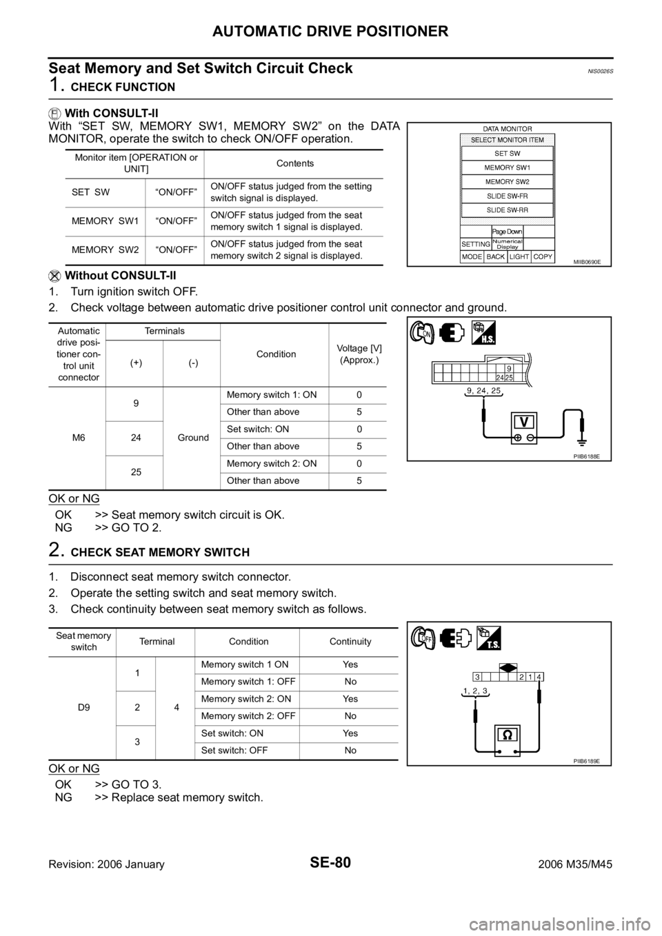
Seat Memory and Set Switch Circuit CheckNIS0026S
1. CHECK FUNCTION
With CONSULT-II
With “SET SW, MEMORY SW1, MEMORY SW2” on the DATA
MONITOR, operate the switch to check ON/OFF operation.
Without CONSULT-II
1. Turn ignition switch OFF.
2. Check voltage between automatic drive positioner control unit connector and ground.
OK or NG
OK >> Seat memory switch circuit is OK.
NG >> GO TO 2.
2. CHECK SEAT MEMORY SWITCH
1. Disconnect seat memory switch connector.
2. Operate the setting switch and seat memory switch.
3. Check continuity between seat memory switch as follows.
OK or NG
OK >> GO TO 3.
NG >> Replace seat memory switch.
Monitor item [OPERATION or
UNIT]Contents
SET SW “ON/OFF”ON/OFF status judged from the setting
switch signal is displayed.
MEMORY SW1 “ON/OFF”ON/OFF status judged from the seat
memory switch 1 signal is displayed.
MEMORY SW2 “ON/OFF”ON/OFF status judged from the seat
memory switch 2 signal is displayed.
Automatic
drive posi-
tioner con-
trol unit
connectorTerminals
ConditionVoltage [V]
(Approx.)
(+) (-)
M69
GroundMemory switch 1: ON 0
Other than above 5
24Set switch: ON 0
Other than above 5
25Memory switch 2: ON 0
Other than above 5
MIIB0690E
PIIB6188E
Seat memory
switchTerminal Condition Continuity
D91
4Memory switch 1 ON Yes
Memory switch 1: OFF No
2Memory switch 2: ON Yes
Memory switch 2: OFF No
3Set switch: ON Yes
Set switch: OFF No
PIIB6189E
Page 5262 of 5621
AUTOMATIC DRIVE POSITIONER
SE-81
C
D
E
F
G
H
J
K
L
MA
B
SE
Revision: 2006 January2006 M35/M45
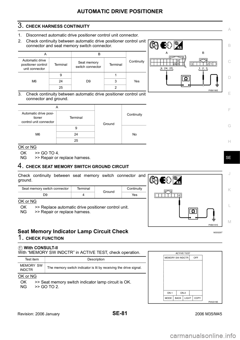
3. CHECK HARNESS CONTINUITY
1. Disconnect automatic drive positioner control unit connector.
2. Check continuity between automatic drive positioner control unit
connector and seat memory switch connector.
3. Check continuity between automatic drive positioner control unit
connector and ground.
OK or NG
OK >> GO TO 4.
NG >> Repair or replace harness.
4. CHECK SEAT MEMORY SWITCH GROUND CIRCUIT
Check continuity between seat memory switch connector and
ground.
OK or NG
OK >> Replace automatic drive positioner control unit.
NG >> Repair or replace harness.
Seat Memory Indicator Lamp Circuit CheckNIS0026T
1. CHECK FUNCTION
With CONSULT-II
With “MEMORY SW INDCTR” in ACTIVE TEST, check operation.
OK or NG
OK >> Seat memory switch indicator lamp circuit is OK.
NG >> GO TO 2.
AB
Continuity Automatic drive
positioner control
unit connectorTerminalSeat memory
switch connectorTerminal
M69
D91
Ye s 24 3
25 2
A
GroundContinuity Automatic drive posi-
tioner
control unit connectorTerminal
M69
No 24
25
PIIB6190E
Seat memory switch connector Terminal
GroundContinuity
D9 4 Yes
PIIB6191E
Test item Description
MEMORY SW
INDCTRThe memory switch indicator is lit by receiving the drive signal.
PIIA0319E
Page 5263 of 5621
SE-82
AUTOMATIC DRIVE POSITIONER
Revision: 2006 January2006 M35/M45
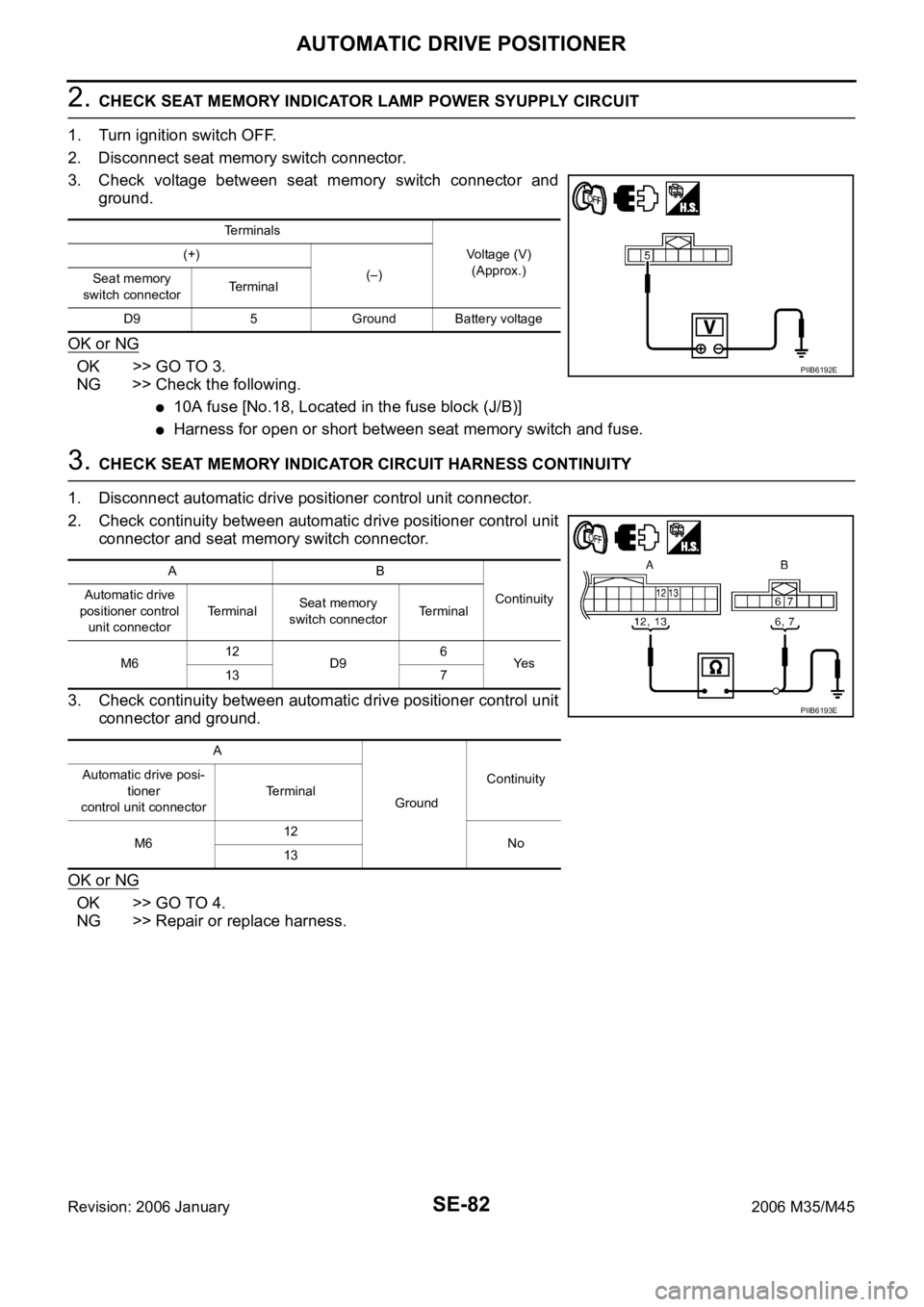
2. CHECK SEAT MEMORY INDICATOR LAMP POWER SYUPPLY CIRCUIT
1. Turn ignition switch OFF.
2. Disconnect seat memory switch connector.
3. Check voltage between seat memory switch connector and
ground.
OK or NG
OK >> GO TO 3.
NG >> Check the following.
10A fuse [No.18, Located in the fuse block (J/B)]
Harness for open or short between seat memory switch and fuse.
3. CHECK SEAT MEMORY INDICATOR CIRCUIT HARNESS CONTINUITY
1. Disconnect automatic drive positioner control unit connector.
2. Check continuity between automatic drive positioner control unit
connector and seat memory switch connector.
3. Check continuity between automatic drive positioner control unit
connector and ground.
OK or NG
OK >> GO TO 4.
NG >> Repair or replace harness.
Terminals
Voltage (V)
(Approx.) (+)
(–)
Seat memory
switch connectorTerminal
D9 5 Ground Battery voltage
PIIB6192E
AB
Continuity Automatic drive
positioner control
unit connectorTe r m i n a lSeat memory
switch connectorTerminal
M612
D96
Ye s
13 7
A
GroundContinuity Automatic drive posi-
tioner
control unit connectorTerminal
M612
No
13
PIIB6193E
Page 5264 of 5621
AUTOMATIC DRIVE POSITIONER
SE-83
C
D
E
F
G
H
J
K
L
MA
B
SE
Revision: 2006 January2006 M35/M45
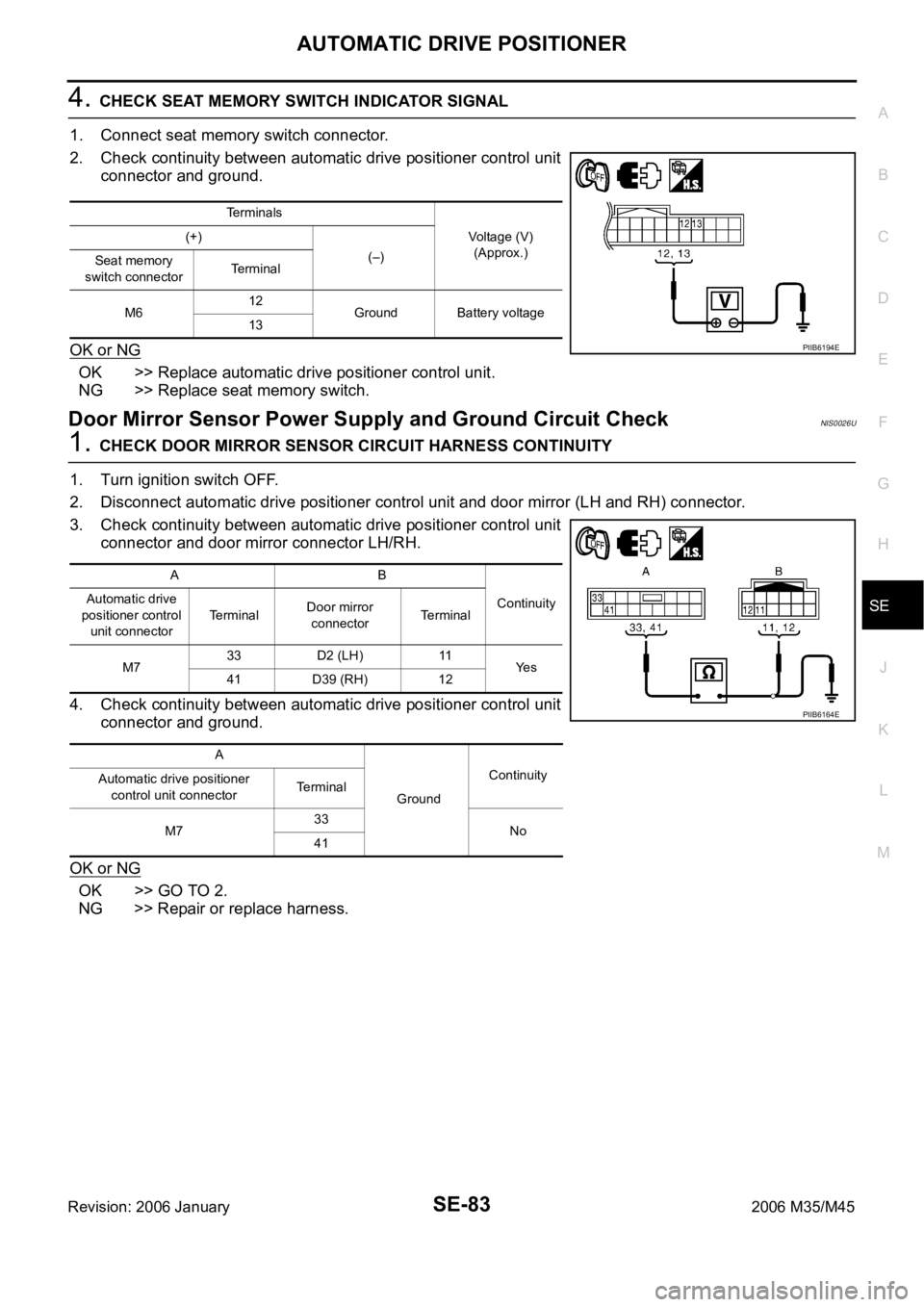
4. CHECK SEAT MEMORY SWITCH INDICATOR SIGNAL
1. Connect seat memory switch connector.
2. Check continuity between automatic drive positioner control unit
connector and ground.
OK or NG
OK >> Replace automatic drive positioner control unit.
NG >> Replace seat memory switch.
Door Mirror Sensor Power Supply and Ground Circuit CheckNIS0026U
1. CHECK DOOR MIRROR SENSOR CIRCUIT HARNESS CONTINUITY
1. Turn ignition switch OFF.
2. Disconnect automatic drive positioner control unit and door mirror (LH and RH) connector.
3. Check continuity between automatic drive positioner control unit
connector and door mirror connector LH/RH.
4. Check continuity between automatic drive positioner control unit
connector and ground.
OK or NG
OK >> GO TO 2.
NG >> Repair or replace harness.
Terminals
Voltage (V)
(Approx.) (+)
(–)
Seat memory
switch connectorTerminal
M612
Ground Battery voltage
13
PIIB6194E
AB
Continuity Automatic drive
positioner control
unit connectorTerminalDoor mirror
connectorTerminal
M733 D2 (LH) 11
Ye s
41 D39 (RH) 12
A
GroundContinuity
Automatic drive positioner
control unit connectorTerminal
M733
No
41
PIIB6164E
Page 5407 of 5621
SRS-46
SIDE AIR BAG (SATELLITE) SENSOR
Revision: 2006 January2006 M35/M45
SIDE AIR BAG (SATELLITE) SENSORPFP:98830
Removal and InstallationNHS0009H
REMOVAL
CAUTION:
Before servicing, turn ignition switch OFF, disconnect both battery terminal and wait at least 3
minutes.
Do not use air tools or electric tools for servicing.
Do not use old fixing nuts after removal; replace with new nuts.
Do not make an impact to the side air bag (satellite) sensor by dropping etc. Replace the side air
bag (satellite) sensor if it has been dropped or sustained an impact.
Replace the satellite sensor of deployed SRS front side air bag and deployed SRS side curtain air
bag.
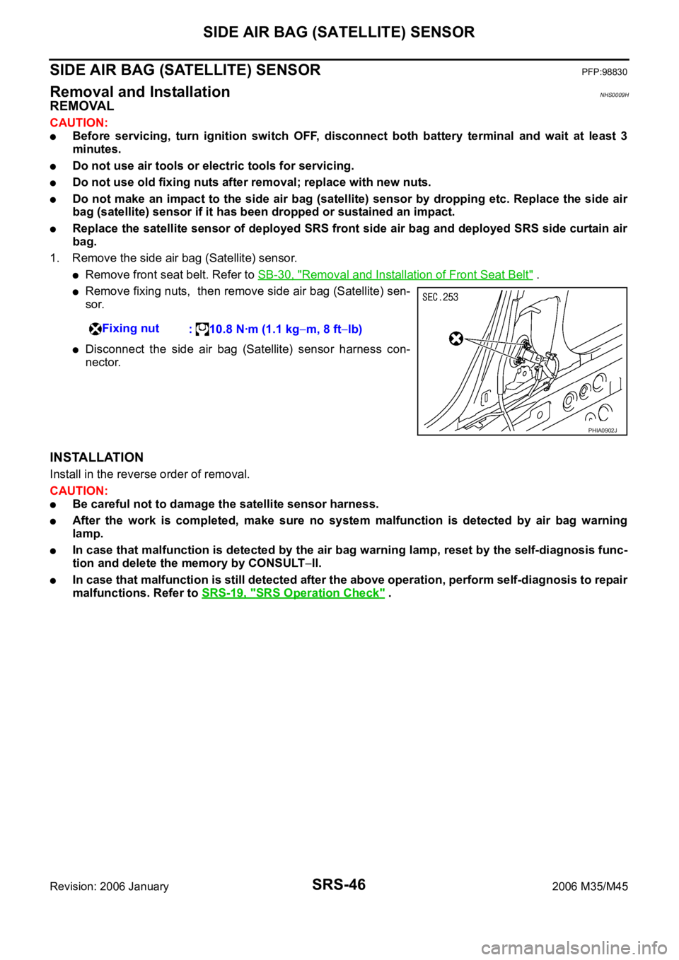
1. Remove the side air bag (Satellite) sensor.
Remove front seat belt. Refer to SB-30, "Removal and Installation of Front Seat Belt" .
Remove fixing nuts, then remove side air bag (Satellite) sen-
sor.
Disconnect the side air bag (Satellite) sensor harness con-
nector.
INSTALLATION
Install in the reverse order of removal.
CAUTION:
Be careful not to damage the satellite sensor harness.
After the work is completed, make sure no system malfunction is detected by air bag warning
lamp.
In case that malfunction is detected by the air bag warning lamp, reset by the self-diagnosis func-
tion and delete the memory by CONSULT
ll.
In case that malfunction is still detected after the above operation, perform self-diagnosis to repair
malfunctions. Refer to SRS-19, "
SRS Operation Check" . Fixing nut
: 10.8 Nꞏm (1.1 kg
m, 8 ftlb)
PHIA0902J