2006 INFINITI M35 key
[x] Cancel search: keyPage 1504 of 5621

WARNING CHIME
DI-71
C
D
E
F
G
H
I
J
L
MA
B
DI
Revision: 2006 January2006 M35/M45
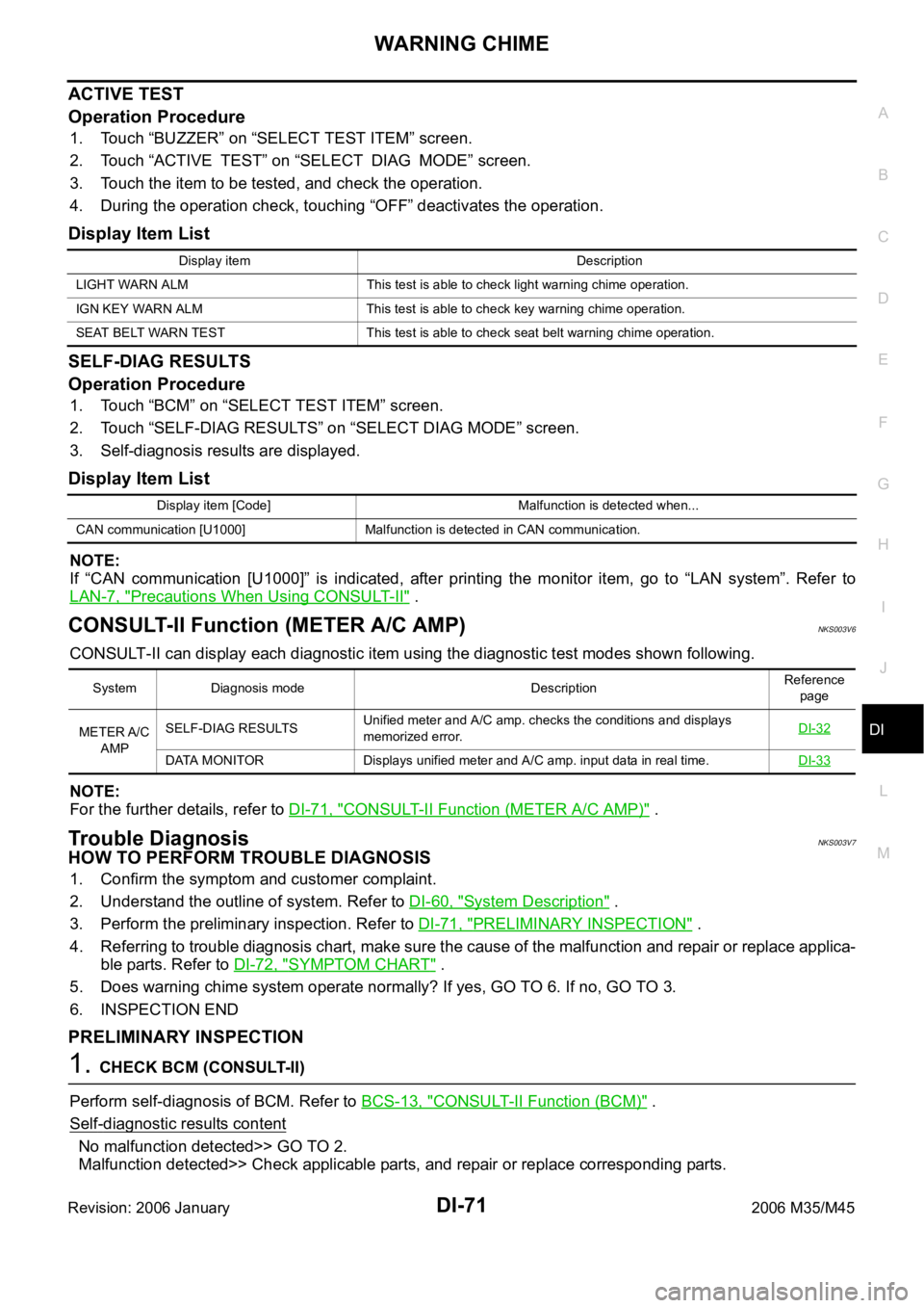
ACTIVE TEST
Operation Procedure
1. Touch “BUZZER” on “SELECT TEST ITEM” screen.
2. Touch “ACTIVE TEST” on “SELECT DIAG MODE” screen.
3. Touch the item to be tested, and check the operation.
4. During the operation check, touching “OFF” deactivates the operation.
Display Item List
SELF-DIAG RESULTS
Operation Procedure
1. Touch “BCM” on “SELECT TEST ITEM” screen.
2. Touch “SELF-DIAG RESULTS” on “SELECT DIAG MODE” screen.
3. Self-diagnosis results are displayed.
Display Item List
NOTE:
If “CAN communication [U1000]” is indicated, after printing the monitor item, go to “LAN system”. Refer to
LAN-7, "
Precautions When Using CONSULT-II" .
CONSULT-II Function (METER A/C AMP)NKS003V6
CONSULT-II can display each diagnostic item using the diagnostic test modes shown following.
NOTE:
For the further details, refer to DI-71, "
CONSULT-II Function (METER A/C AMP)" .
Trouble DiagnosisNKS003V7
HOW TO PERFORM TROUBLE DIAGNOSIS
1. Confirm the symptom and customer complaint.
2. Understand the outline of system. Refer to DI-60, "
System Description" .
3. Perform the preliminary inspection. Refer to DI-71, "
PRELIMINARY INSPECTION" .
4. Referring to trouble diagnosis chart, make sure the cause of the malfunction and repair or replace applica-
ble parts. Refer to DI-72, "
SYMPTOM CHART" .
5. Does warning chime system operate normally? If yes, GO TO 6. If no, GO TO 3.
6. INSPECTION END
PRELIMINARY INSPECTION
1. CHECK BCM (CONSULT-II)
Perform self-diagnosis of BCM. Refer to BCS-13, "
CONSULT-II Function (BCM)" .
Self
-diagnostic results content
No malfunction detected>> GO TO 2.
Malfunction detected>> Check applicable parts, and repair or replace corresponding parts.
Display item Description
LIGHT WARN ALM This test is able to check light warning chime operation.
IGN KEY WARN ALM This test is able to check key warning chime operation.
SEAT BELT WARN TEST This test is able to check seat belt warning chime operation.
Display item [Code] Malfunction is detected when...
CAN communication [U1000] Malfunction is detected in CAN communication.
System Diagnosis mode DescriptionReference
page
METER A/C
AMPSELF-DIAG RESULTSUnified meter and A/C amp. checks the conditions and displays
memorized error.DI-32
DATA MONITOR Displays unified meter and A/C amp. input data in real time.DI-33
Page 1505 of 5621

DI-72
WARNING CHIME
Revision: 2006 January2006 M35/M45
2. CHECK UNIFIED METER AND A/C AMP. (CONSULT-II)
Perform self-diagnosis of unified meter and A/C amp. Refer to DI-71, "
CONSULT-II Function (METER A/C
AMP)" .
Self
-diagnostic results content
No malfunction detected>> INSPECTION END
Malfunction detected>> Check applicable parts, and repair or replace corresponding parts.
SYMPTOM CHART
Meter Buzzer Circuit InspectionNKS003V8
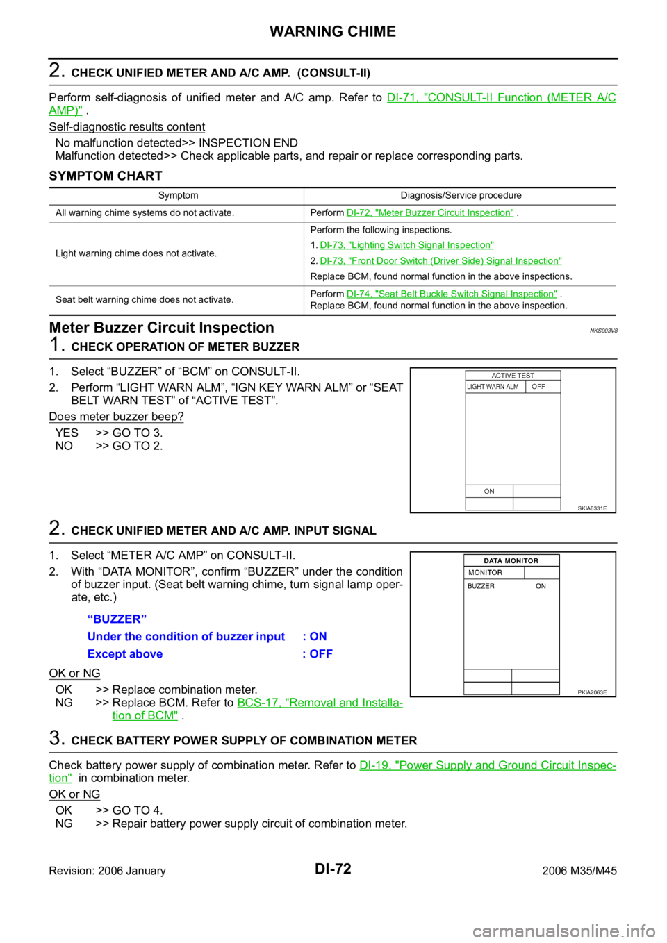
1. CHECK OPERATION OF METER BUZZER
1. Select “BUZZER” of “BCM” on CONSULT-II.
2. Perform “LIGHT WARN ALM”, “IGN KEY WARN ALM” or “SEAT
BELT WARN TEST” of “ACTIVE TEST”.
Does meter buzzer beep?
YES >> GO TO 3.
NO >> GO TO 2.
2. CHECK UNIFIED METER AND A/C AMP. INPUT SIGNAL
1. Select “METER A/C AMP” on CONSULT-II.
2. With “DATA MONITOR”, confirm “BUZZER” under the condition
of buzzer input. (Seat belt warning chime, turn signal lamp oper-
ate, etc.)
OK or NG
OK >> Replace combination meter.
NG >> Replace BCM. Refer to BCS-17, "
Removal and Installa-
tion of BCM" .
3. CHECK BATTERY POWER SUPPLY OF COMBINATION METER
Check battery power supply of combination meter. Refer to DI-19, "
Power Supply and Ground Circuit Inspec-
tion" in combination meter.
OK or NG
OK >> GO TO 4.
NG >> Repair battery power supply circuit of combination meter.
Symptom Diagnosis/Service procedure
All warning chime systems do not activate. Perform DI-72, "
Meter Buzzer Circuit Inspection" .
Light warning chime does not activate.Perform the following inspections.
1.DI-73, "
Lighting Switch Signal Inspection"
2.DI-73, "Front Door Switch (Driver Side) Signal Inspection"
Replace BCM, found normal function in the above inspections.
Seat belt warning chime does not activate.Perform DI-74, "
Seat Belt Buckle Switch Signal Inspection" .
Replace BCM, found normal function in the above inspection.
SKIA6331E
“BUZZER”
Under the condition of buzzer input : ON
Except above : OFF
PKIA2063E
Page 1519 of 5621

DI-86
LANE DEPARTURE WARNING SYSTEM
Revision: 2006 January2006 M35/M45
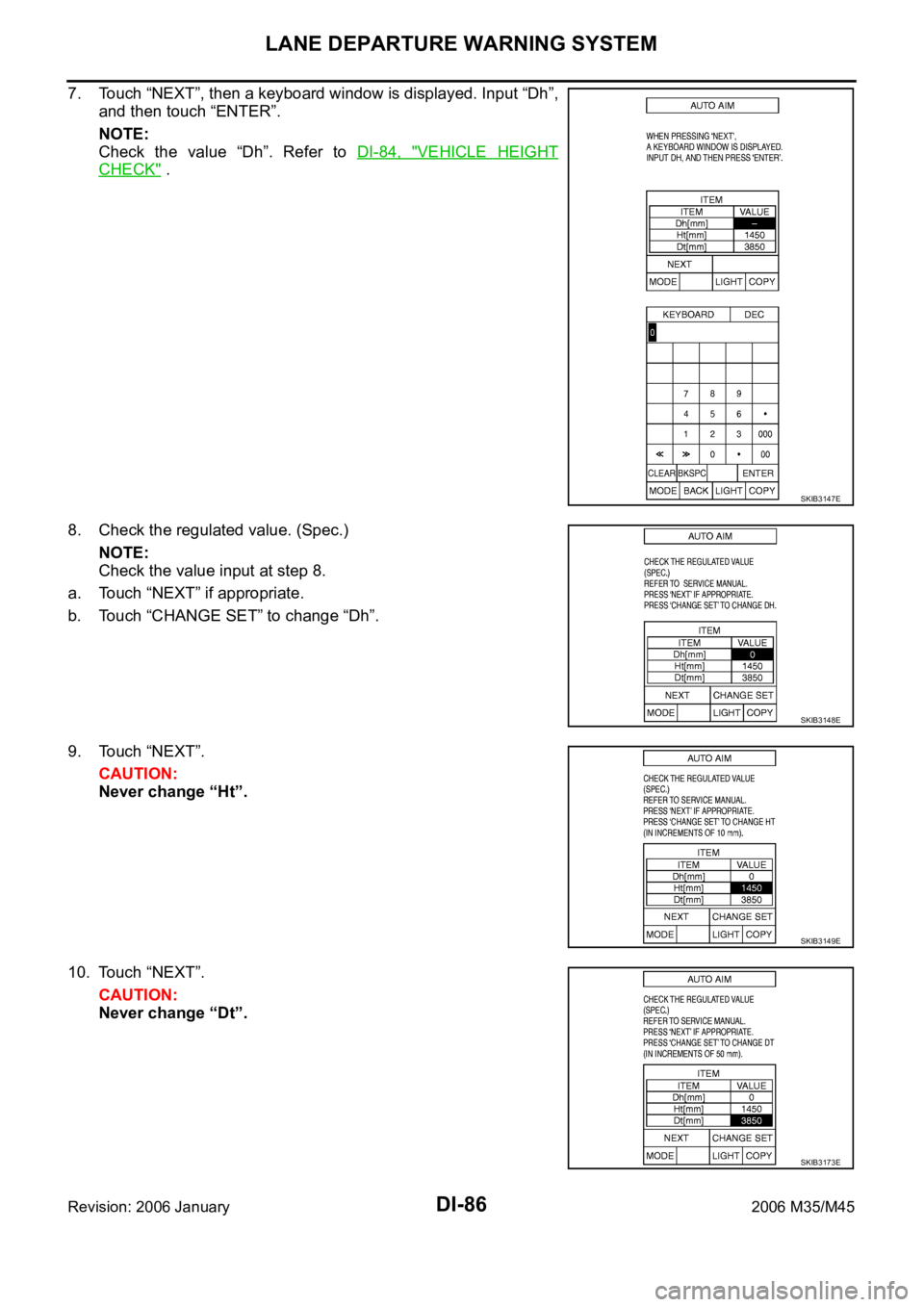
7. Touch “NEXT”, then a keyboard window is displayed. Input “Dh”,
and then touch “ENTER”.
NOTE:
Check the value “Dh”. Refer to DI-84, "
VEHICLE HEIGHT
CHECK" .
8. Check the regulated value. (Spec.)
NOTE:
Check the value input at step 8.
a. Touch “NEXT” if appropriate.
b. Touch “CHANGE SET” to change “Dh”.
9. Touch “NEXT”.
CAUTION:
Never change “Ht”.
10. Touch “NEXT”.
CAUTION:
Never change “Dt”.
SKIB3147E
SKIB3148E
SKIB3149E
SKIB3173E
Page 1596 of 5621
![INFINITI M35 2006 Factory Service Manual IVIS (INFINITI VEHICLE IMMOBILIZER SYSTEM-NATS)
EC-53
[VQ35DE]
C
D
E
F
G
H
I
J
K
L
MA
EC
Revision: 2006 January2006 M35/M45
IVIS (INFINITI VEHICLE IMMOBILIZER SYSTEM-NATS)PFP:28591
DescriptionNBS004SK INFINITI M35 2006 Factory Service Manual IVIS (INFINITI VEHICLE IMMOBILIZER SYSTEM-NATS)
EC-53
[VQ35DE]
C
D
E
F
G
H
I
J
K
L
MA
EC
Revision: 2006 January2006 M35/M45
IVIS (INFINITI VEHICLE IMMOBILIZER SYSTEM-NATS)PFP:28591
DescriptionNBS004SK](/manual-img/42/57023/w960_57023-1595.png)
IVIS (INFINITI VEHICLE IMMOBILIZER SYSTEM-NATS)
EC-53
[VQ35DE]
C
D
E
F
G
H
I
J
K
L
MA
EC
Revision: 2006 January2006 M35/M45
IVIS (INFINITI VEHICLE IMMOBILIZER SYSTEM-NATS)PFP:28591
DescriptionNBS004SK
If the security indicator lights up with the ignition switch in
the ON position or “NATS MALFUNCTION” is displayed on
“SELF-DIAG RESULTS” screen, perform self-diagnostic
results mode with CONSULT-II using NATS program card.
Refer to BL-248, "
IVIS (INFINITI VEHICLE IMMOBILIZER
SYSTEM-NATS)" .
Confirm no self-diagnostic results of IVIS (NATS) is dis-
played before touching “ERASE” in “SELF-DIAG RESULTS”
mode with CONSULT-II.
When replacing ECM, initialization of IVIS (NATS) system
and registration of all IVIS (NATS) ignition key IDs must be
carried out with CONSULT-II using NATS program card.
Therefore, be sure to receive all keys from vehicle owner. Regarding the procedures of IVIS (NATS)
initialization and all IVIS (NATS) ignition key ID registration, refer to CONSULT-II Operation Manual,
IVIS/NVIS.
SEF543X
Page 1612 of 5621
![INFINITI M35 2006 Factory Service Manual ON BOARD DIAGNOSTIC (OBD) SYSTEM
EC-69
[VQ35DE]
C
D
E
F
G
H
I
J
K
L
MA
EC
Revision: 2006 January2006 M35/M45
–Te s t v a l u e s
Actual work procedures are explained using a DTC as an example. Be INFINITI M35 2006 Factory Service Manual ON BOARD DIAGNOSTIC (OBD) SYSTEM
EC-69
[VQ35DE]
C
D
E
F
G
H
I
J
K
L
MA
EC
Revision: 2006 January2006 M35/M45
–Te s t v a l u e s
Actual work procedures are explained using a DTC as an example. Be](/manual-img/42/57023/w960_57023-1611.png)
ON BOARD DIAGNOSTIC (OBD) SYSTEM
EC-69
[VQ35DE]
C
D
E
F
G
H
I
J
K
L
MA
EC
Revision: 2006 January2006 M35/M45
–Te s t v a l u e s
Actual work procedures are explained using a DTC as an example. Be careful so that not only the DTC, but all
of the data listed above, are cleared from the ECM memory during work procedures.
Malfunction Indicator Lamp (MIL)NBS004SO
DESCRIPTION
The MIL is located on the instrument panel.
1. The MIL will light up when the ignition switch is turned ON with-
out the engine running. This is a bulb check.
If the MIL does not light up, refer to DI-40, "
WARNING LAMPS" ,
or see EC-722, "
MIL AND DATA LINK CONNECTOR" .
2. When the engine is started, the MIL should go off.
If the MIL remains on, the on board diagnostic system has
detected an engine system malfunction.
ON BOARD DIAGNOSTIC SYSTEM FUNCTION
The on board diagnostic system has the following three functions.
When there is an open circuit on MIL circuit, the ECM cannot warn the driver by lighting up MIL when there is
malfunction on engine control system.
Therefore, when electrical controlled throttle and part of ECM related diagnoses are continuously detected as
NG for 5 trips, ECM warns the driver that engine control system malfunctions and MIL circuit is open by means
of operating fail-safe function.
The fail-safe function also operates when above diagnoses except MIL circuit are detected and demands the
driver to repair the malfunction.
SEF217U
Diagnostic Test
ModeKEY and ENG.
StatusFunction Explanation of Function
Mode I Ignition switch in
ON position
Engine stoppedBULB CHECK This function checks the MIL bulb for damage (blown,
open circuit, etc.).
If the MIL does not come on, check MIL circuit.
Engine running MALFUNCTION
WARNINGThis is a usual driving condition. When a malfunction is
detected twice in two consecutive driving cycles (two trip
detection logic), the MIL will light up to inform the driver
that a malfunction has been detected.
The following malfunctions will light up or blink the MIL in
the 1st trip.
Misfire (Possible three way catalyst damage)
One trip detection diagnoses
Mode II Ignition switch in
ON position
Engine stoppedSELF-DIAGNOSTIC
RESULTSThis function allows DTCs and 1st trip DTCs to be read.
Engine operating condition in fail-safe mode Engine speed will not rise more than 2,500 rpm due to the fuel cut
Page 1622 of 5621
![INFINITI M35 2006 Factory Service Manual BASIC SERVICE PROCEDURE
EC-79
[VQ35DE]
C
D
E
F
G
H
I
J
K
L
MA
EC
Revision: 2006 January2006 M35/M45
6. PERFORM IDLE AIR VOLUME LEARNING
Refer to EC-96, "
Idle Air Volume Learning" .
Is Idle Ai INFINITI M35 2006 Factory Service Manual BASIC SERVICE PROCEDURE
EC-79
[VQ35DE]
C
D
E
F
G
H
I
J
K
L
MA
EC
Revision: 2006 January2006 M35/M45
6. PERFORM IDLE AIR VOLUME LEARNING
Refer to EC-96, "
Idle Air Volume Learning" .
Is Idle Ai](/manual-img/42/57023/w960_57023-1621.png)
BASIC SERVICE PROCEDURE
EC-79
[VQ35DE]
C
D
E
F
G
H
I
J
K
L
MA
EC
Revision: 2006 January2006 M35/M45
6. PERFORM IDLE AIR VOLUME LEARNING
Refer to EC-96, "
Idle Air Volume Learning" .
Is Idle Air Volume Learning carried out successfully?
Ye s o r N o
Ye s > > G O T O 7 .
No >> 1. Follow the instruction of Idle Air Volume Learning.
2. GO TO 4.
7. CHECK TARGET IDLE SPEED AGAIN
With CONSULT-II
1. Start engine and warm it up to normal operating temperature.
2. Read idle speed in “DATA MONITOR” mode with CONSULT-II.
Refer to EC-82, "
IDLE SPEED" .
Without CONSULT-II
1. Start engine and warm it up to normal operating temperature.
2. Check idle speed.
Refer to EC-82, "
IDLE SPEED" .
OK or NG
OK >> GO TO 10.
NG >> GO TO 8.
8. DETECT MALFUNCTIONING PART
Check the Following.
Check camshaft position sensor (PHASE) and circuit. Refer to EC-383, "DTC P0340, P0345 CMP SEN-
SOR (PHASE)" .
Check crankshaft position sensor (POS) and circuit. Refer to EC-376, "DTC P0335 CKP SENSOR (POS)"
.
OK or NG
OK >> GO TO 9.
NG >> 1. Repair or replace.
2. GO TO 4.
9. CHECK ECM FUNCTION
1. Substitute another known-good ECM to check ECM function. (ECM may be the cause of an incident, but
this is a rare case.)
2. Perform initialization of IVIS (NATS) system and registration of all IVIS (NATS) ignition key IDs. Refer to
BL-252, "
ECM Re-Communicating Function" .
>> GO TO 4. 650
50 rpm (in P or N position)
650
50 rpm (in P or N position)
SEF174Y
Page 1624 of 5621
![INFINITI M35 2006 Factory Service Manual BASIC SERVICE PROCEDURE
EC-81
[VQ35DE]
C
D
E
F
G
H
I
J
K
L
MA
EC
Revision: 2006 January2006 M35/M45
15. CHECK IGNITION TIMING AGAIN
1. Run engine at idle.
2. Check ignition timing with a timing light. INFINITI M35 2006 Factory Service Manual BASIC SERVICE PROCEDURE
EC-81
[VQ35DE]
C
D
E
F
G
H
I
J
K
L
MA
EC
Revision: 2006 January2006 M35/M45
15. CHECK IGNITION TIMING AGAIN
1. Run engine at idle.
2. Check ignition timing with a timing light.](/manual-img/42/57023/w960_57023-1623.png)
BASIC SERVICE PROCEDURE
EC-81
[VQ35DE]
C
D
E
F
G
H
I
J
K
L
MA
EC
Revision: 2006 January2006 M35/M45
15. CHECK IGNITION TIMING AGAIN
1. Run engine at idle.
2. Check ignition timing with a timing light.
Refer to EC-82, "
IGNITION TIMING" .
OK or NG
OK >> GO TO 19.
NG >> GO TO 16.
16. CHECK TIMING CHAIN INSTALLATION
Check timing chain installation. Refer to EM-64, "
TIMING CHAIN" .
OK or NG
OK >> GO TO 17.
NG >> 1. Repair the timing chain installation.
2. GO TO 4.
17. DETECT MALFUNCTIONING PART
Check the following.
Check camshaft position sensor (PHASE) and circuit. Refer to EC-383, "DTC P0340, P0345 CMP SEN-
SOR (PHASE)" .
Check crankshaft position sensor (POS) and circuit. Refer to EC-376, "DTC P0335 CKP SENSOR (POS)"
.
OK or NG
OK >> GO TO 18.
NG >> 1. Repair or replace.
2. GO TO 4.
18. CHECK ECM FUNCTION
1. Substitute another known-good ECM to check ECM function. (ECM may be the cause of an incident, but
this is a rare case.)
2. Perform initialization of IVIS (NATS) system and registration of all IVIS (NATS) ignition key IDs. Refer to
BL-252, "
ECM Re-Communicating Function" .
>> GO TO 4.
19. INSPECTION END
Did you replace ECM, referring this Basic Inspection procedure?
Ye s o r N o
Ye s > > 1 . P e r f o r m EC-95, "VIN Registration" .
2.INSPECTION END
No >>INSPECTION END 15
5 BTDC (in P or N position)
PBIB1602E
Page 1631 of 5621
![INFINITI M35 2006 Factory Service Manual EC-88
[VQ35DE]
BASIC SERVICE PROCEDURE
Revision: 2006 January2006 M35/M45
6. PERFORM IDLE AIR VOLUME LEARNING
Perform EC-96, "
Idle Air Volume Learning" .
Is Idle Air Volume Learning carried o INFINITI M35 2006 Factory Service Manual EC-88
[VQ35DE]
BASIC SERVICE PROCEDURE
Revision: 2006 January2006 M35/M45
6. PERFORM IDLE AIR VOLUME LEARNING
Perform EC-96, "
Idle Air Volume Learning" .
Is Idle Air Volume Learning carried o](/manual-img/42/57023/w960_57023-1630.png)
EC-88
[VQ35DE]
BASIC SERVICE PROCEDURE
Revision: 2006 January2006 M35/M45
6. PERFORM IDLE AIR VOLUME LEARNING
Perform EC-96, "
Idle Air Volume Learning" .
Is Idle Air Volume Learning carried out successfully?
Ye s o r N o
Yes >> GO TO 7.
No >> 1. Follow the instruction of Idle Air Volume Learning.
2. GO TO 4.
7. CHECK TARGET IDLE SPEED AGAIN
With CONSULT-II
1. Start engine and warm it up to normal operating temperature.
2. Read idle speed in “DATA MONITOR” mode with CONSULT-II.
Refer to EC-82, "
IDLE SPEED" .
Without CONSULT-II
1. Start engine and warm it up to normal operating temperature.
2. Check idle speed.
Refer to EC-82, "
IDLE SPEED" .
OK or NG
OK >> GO TO 10.
NG >> GO TO 8.
8. DETECT MALFUNCTIONING PART
Check the following.
Check camshaft position sensor (PHASE) and circuit. Refer to EC-383, "DTC P0340, P0345 CMP SEN-
SOR (PHASE)" .
Check crankshaft position sensor (POS) and circuit. Refer to EC-376, "DTC P0335 CKP SENSOR (POS)"
.
OK or NG
OK >> GO TO 9.
NG >> 1. Repair or replace.
2. GO TO 4.
9. CHECK ECM FUNCTION
1. Substitute another known-good ECM to check ECM function. (ECM may be the cause of an incident, but
this is a rare case.)
2. Perform initialization of IVIS (NATS) system and registration of all IVIS (NATS) ignition key IDs. Refer to
BL-252, "
ECM Re-Communicating Function" .
>> GO TO 4. 650
50 rpm (in P or N position)
650
50 rpm (in P or N position)