Page 1171 of 5621

BL-232
VEHICLE SECURITY (THEFT WARNING) SYSTEM
Revision: 2006 January2006 M35/M45
Terminals and Reference Value of BCMNIS001ZZ
Terminals and Reference Value of IPDM E/RNIS00200
Terminal Wire color Item ConditionVoltage [V]
(Approx.)
11 V Power supply (ACC) Ignition switch (ACC or ON position) Battery voltage
12 PFront door switch
passenger side signalON (Open)
OFF (Closed) 0 Battery voltage
13 O/L Rear door switch RH signal ON (Open)
OFF (Closed) 0 Battery voltage
22 G Power window serial linkIgnition switch ON or power window
timer operating
23 W/V Security indicator lamp Goes off
Illuminates Battery voltage 0
37 LG Key switch signalKey inserted in key slot
key
removed from key slotBattery voltage 0
39 L CAN-H — —
40 P CAN-L — —
42 P Power source (fuse) — Battery voltage
52 B Ground — 0
55 W Battery power supply (fusible link) — Battery voltage
56 W Trunk lid key cylinder switch Neutral
Unlock Battery voltage 0
57 SB Trunk room lamp switch signal ON (Open)
OFF (Closed) 0 Battery voltage
62 VFront door switch
driver side signalON (Open)
OFF (Closed) 0 Battery voltage
63 R/G Rear door switch LH signal ON (Open)
OFF (Closed) 0 Battery voltage
PIIA2344J
Terminal Wire color Item ConditionVoltage [V]
(Approx.)
38 B Ground (power) — 0
48 G/B Horn relay control signalPanic alarm is operating 0
Other than above Battery voltage
49 L CAN-H — —
50 P CAN-L — —
51 B Ground (signal) — 0
60 LG/B Hood switch signal ON (Open)
OFF (closed) 0 Battery voltage
Page 1173 of 5621

BL-234
VEHICLE SECURITY (THEFT WARNING) SYSTEM
Revision: 2006 January2006 M35/M45
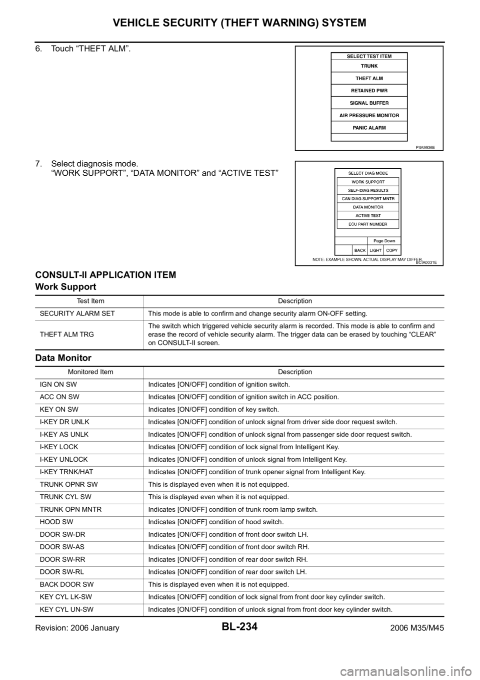
6. Touch “THEFT ALM”.
7. Select diagnosis mode.
“WORK SUPPORT”, “DATA MONITOR” and “ACTIVE TEST”
CONSULT-II APPLICATION ITEM
Work Support
Data Monitor
PIIA9936E
BCIA0031E
Test Item Description
SECURITY ALARM SET This mode is able to confirm and change security alarm ON-OFF setting.
THEFT ALM TRGThe switch which triggered vehicle security alarm is recorded. This mode is able to confirm and
erase the record of vehicle security alarm. The trigger data can be erased by touching “CLEAR”
on CONSULT-II screen.
Monitored Item Description
IGN ON SW Indicates [ON/OFF] condition of ignition switch.
ACC ON SW Indicates [ON/OFF] condition of ignition switch in ACC position.
KEY ON SW Indicates [ON/OFF] condition of key switch.
I-KEY DR UNLK Indicates [ON/OFF] condition of unlock signal from driver side door request switch.
I-KEY AS UNLK Indicates [ON/OFF] condition of unlock signal from passenger side door request switch.
I-KEY LOCK Indicates [ON/OFF] condition of lock signal from Intelligent Key.
I-KEY UNLOCK Indicates [ON/OFF] condition of unlock signal from Intelligent Key.
I-KEY TRNK/HAT Indicates [ON/OFF] condition of trunk opener signal from Intelligent Key.
TRUNK OPNR SW This is displayed even when it is not equipped.
TRUNK CYL SW This is displayed even when it is not equipped.
TRUNK OPN MNTR Indicates [ON/OFF] condition of trunk room lamp switch.
HOOD SW Indicates [ON/OFF] condition of hood switch.
DOOR SW-DR Indicates [ON/OFF] condition of front door switch LH.
DOOR SW-AS Indicates [ON/OFF] condition of front door switch RH.
DOOR SW-RR Indicates [ON/OFF] condition of rear door switch RH.
DOOR SW-RL Indicates [ON/OFF] condition of rear door switch LH.
BACK DOOR SW This is displayed even when it is not equipped.
KEY CYL LK-SW Indicates [ON/OFF] condition of lock signal from front door key cylinder switch.
KEY CYL UN-SW Indicates [ON/OFF] condition of unlock signal from front door key cylinder switch.
Page 1174 of 5621

VEHICLE SECURITY (THEFT WARNING) SYSTEM
BL-235
C
D
E
F
G
H
J
K
L
MA
B
BL
Revision: 2006 January2006 M35/M45
Active Test
Trouble Diagnosis Work FlowNIS00202
1. CHECK IN
Listen to customer complaint.
>> GO TO 2.
2. CHECK FUNCTION
Do “Power door lock system” and “Intelligent Key system” work properly?
YES >> GO TO 3.
NO >> Preform diagnosis and repair. Refer to .
3. PERFORM DIAGNOSTIC PROCEDURE
Perform diagnostic procedure according to the symptom chart. Refer to BL-237, "
Trouble Diagnosis Symptom
Chart" .
>> GO TO 4.
4. FINAL CHECK
Confirm that the malfunction is completely fixed by operating the system.
OK >> INSPECTION END
NG >> GO TO 3.
Preliminary CheckNIS00203
1. INSPECTION START
Turn ignition switch "OFF" and pull out Intelligent Key from key slot.
NOTE:
Before starting operation check, open front windows.
>> GO TO 2.
CDL LOCK SW Indicates [ON/OFF] condition of lock signal from door lock/unlock switch LH and RH.
CDL UNLOCK SW Indicates [ON/OFF] condition of unlock signal from door lock/unlock switch LH and RH. Monitored Item Description
Test Item Description
THEFT INDThis test is able to check security indicator lamp operation. The lamp will be turned on when “ON”
on CONSULT-II screen is touched.
VEHICLE SECURITY HORNThis test is able to check vehicle security horn operation. The horns will be activated for 0.5 sec-
onds after “ON” on CONSULT-II screen is touched.
HEADLAMP(HI)This test is able to check vehicle security lamp operation. The headlamps will be activated for 0.5
seconds after “ON” on CONSULT-II screen is touched.
FLASHERThis test is able to check vehicle security hazard lamp operation. The hazard lamps will be acti-
vated after “ON” on CONSULT-II screen is touched.
Page 1175 of 5621

BL-236
VEHICLE SECURITY (THEFT WARNING) SYSTEM
Revision: 2006 January2006 M35/M45
2. CHECK SECURITY INDICATOR LAMP
1. Lock doors using Intelligent Key or mechanical key.
2. Make sure security indicator lamp illuminate for 30 seconds.
Security indicator lamp should illuminate.
OK >> GO TO 3.
NG >> Perform diagnosis and repair. Refer to BL-238, "
Diagnostic Procedure 1" .
3. CHECK ALARM FUNCTION
1. After 30 seconds, security indicator lamp will start blink.
2. Open any door or hood before unlocking with Intelligent Key or mechanical key, or open trunk lid without
Intelligent Key or mechanical key.
Do alarm function properly.
OK >> GO TO 4.
NG >> Check the following.
The vehicle security system does not phase in alarm mode. Refer to BL-245, "Diagnostic Pro-
cedure 2" .
Alarm (horn, headlamp and hazard lamp) do not operate. Refer to BL-246, "Diagnostic Proce-
dure 3" .
4. CHECK ALARM CANCEL OPERATION
Unlock any door or open trunk lid useing Intelligent Key or mechanical key.
Alarm (horn, headlamp and hazard lamp) should stop.
OK >> INSPECTION END.
NG >> Perform diagnosis and repair. Refer to BL-246, "
Diagnostic Procedure 4" .
Page 1176 of 5621

VEHICLE SECURITY (THEFT WARNING) SYSTEM
BL-237
C
D
E
F
G
H
J
K
L
MA
B
BL
Revision: 2006 January2006 M35/M45
Trouble Diagnosis Symptom ChartNIS00204
*: Make sure the system is in the armed phase.Procedure
Diagnostic procedure Refer to page
Symptom
1Vehicle security
system cannot be
set by ꞏꞏꞏꞏDoor switch Diagnostic Procedure 1 (Check door, hood and trunk switch) BL-238
Lock / unlock switch Diagnostic Procedure 6 (Check door lock / unlock switch)BL-247
Door outside key Diagnostic Procedure 3 (Check door key cylinder switch)BL-246
Intelligent Key Check Intelligent Key.BL-126
— If the above systems are “OK”, replace BCM.BCS-17
Security indicator does not turn “ON”.Diagnostic Procedure 2 (Check security indicator lamp)BL-245If the above systems are “OK”, replace BCM.BCS-17
2* Vehicle security
system does not
alarm when ꞏꞏꞏꞏAny door is opened.Diagnostic Procedure 1 (Check door, hood and trunk switch)BL-238If the above systems are “OK”, replace BCM.BCS-17
3Vehicle security
alarm does not
activate.Horn alarmDiagnostic Procedure 4 (Check vehicle security horn alarm)BL-246
If the above systems are “OK”, replace BCM.BCS-17
Head lamp alarmDiagnostic Procedure 5 (Check head lamp alarm)BL-247If the above systems are “OK”, replace BCM.BCS-17
Hazard lampDiagnostic Procedure 7 (Check hazard lamp alarm)BL-247If the above systems are “OK”, replace BCM.BCS-17
4Vehicle security
system cannot be
canceled by ꞏꞏꞏꞏDoor outside keyDiagnostic Procedure 3 (Check door key cylinder switch)BL-246
If the above systems are “OK”, replace power window main
switch.EI-34
Intelligent KeyCheck remote keyless entry function.BL-44If the above systems are “OK”, replace BCM.BCS-17
Page 1185 of 5621

BL-246
VEHICLE SECURITY (THEFT WARNING) SYSTEM
Revision: 2006 January2006 M35/M45
Diagnostic Procedure 3NIS00207
FRONT DOOR KEY CYLINDER SWITCH CHECK
1. CHECK KEY CYLINDER SWITCH OPERATION
Check if door key cylinder switch using mechanical key.
Do doors lock / unlock when using the mechanical key?
YES >> Front door key cylinder switch operation is OK.
NO >> Check door key cylinder switch circuit. Refer to BL-42, "
Door Key Cylinder Switch Check" .
Diagnostic Procedure 4NIS00208
VEHICLE SECURITY HORN ALARM CHECK
First perform the “SELF-DIAG RESULTS” of “BCM” with CONSULT-II, then perform the trouble diagno-
sis of malfunction system indicated in “SELF-DIAG RESULTS” of “BCM”. Refer to BCS-15, "
CAN Com-
munication Inspection Using CONSULT-II (Self-Diagnosis)".
1. CHECK HORN OPERATION
Check if horn sounds with horn switch.
Does horn operate?
Yes >> GO TO 2.
No >> Check horn circuit. Refer to WW-53, "
HORN" .
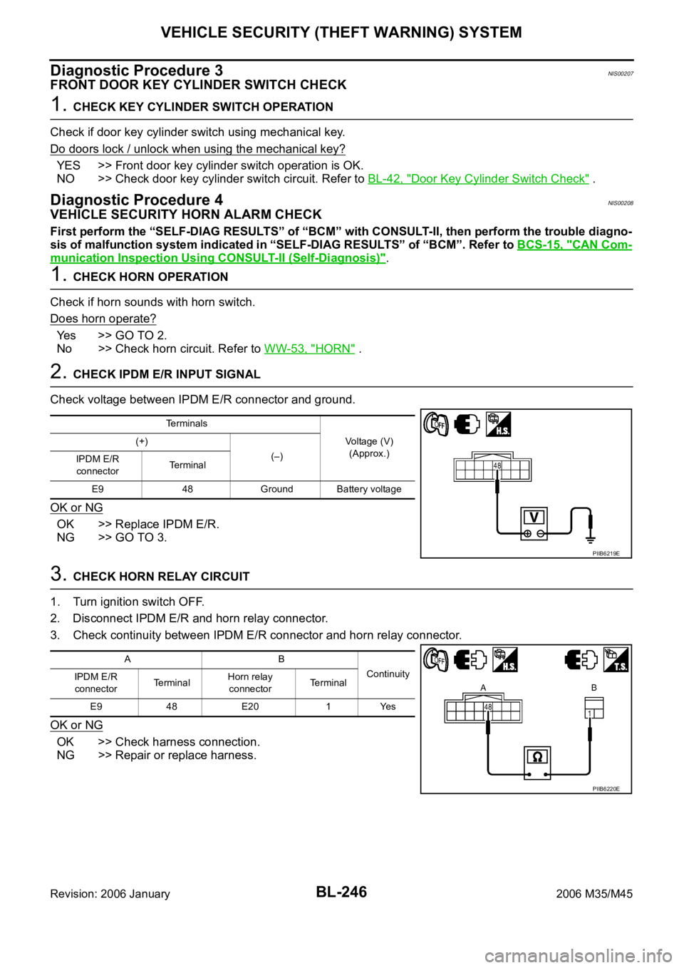
2. CHECK IPDM E/R INPUT SIGNAL
Check voltage between IPDM E/R connector and ground.
OK or NG
OK >> Replace IPDM E/R.
NG >> GO TO 3.
3. CHECK HORN RELAY CIRCUIT
1. Turn ignition switch OFF.
2. Disconnect IPDM E/R and horn relay connector.
3. Check continuity between IPDM E/R connector and horn relay connector.
OK or NG
OK >> Check harness connection.
NG >> Repair or replace harness.
Terminals
Voltage (V)
(Approx.) (+)
(–)
IPDM E/R
connectorTerminal
E9 48 Ground Battery voltage
PIIB6219E
AB
Continuity
IPDM E/R
connectorTe r m i n a lHorn relay
connectorTerminal
E9 48 E20 1 Yes
PIIB6220E
Page 1187 of 5621
BL-248
IVIS (INFINITI VEHICLE IMMOBILIZER SYSTEM-NATS)
Revision: 2006 January2006 M35/M45
IVIS (INFINITI VEHICLE IMMOBILIZER SYSTEM-NATS)PFP:28591
Component Parts and Harness Connector LocationNIS0020C
1. Fuse block (J/B) fuse layout 2. Fuse and fusible link box 3. BCM M1, M2, M3 (View with instru-
ment lower panel RH removed)
4. Intelligent key unit M32, M33 (View
with dash side finisher LH removed) 5. PDU M30, M31 (View with combina-
tion meter removed)6. IPDM E/R E4, E9
(Engine room)
7. ECM M71 (View with instrument
lower panel RH removed)8. Push-button ignition switch M27 9. Stop lamp switch E124
PIIB5894E
Page 1188 of 5621
IVIS (INFINITI VEHICLE IMMOBILIZER SYSTEM-NATS)
BL-249
C
D
E
F
G
H
J
K
L
MA
B
BL
Revision: 2006 January2006 M35/M45
NOTE:
If customer reports a “No start” condition, request ALL KEYS to be brought to an INFINITI dealer to
check for an IVIS (NATS) malfunction.
10. Unified meter and A / C amp M64, M65 11. Combination meter M5212. Multifunction switch M69
(Security indicator)
13. Steering lock unit M35
(Steering column)
PIIB5895E