2006 INFINITI M35 key
[x] Cancel search: keyPage 1219 of 5621

BL-280
IVIS (INFINITI VEHICLE IMMOBILIZER SYSTEM-NATS)
Revision: 2006 January2006 M35/M45
DTC P1611 ID DISCORD, IMM-ECMNIS0020T
Self-diagnostic results:
“ID DISCORD, IMM-ECM” displayed on CONSULT-II screen
1. CONFIRM SELF-DIAGNOSTIC RESULTS
Confirm SELF-DIAGNOSTIC RESULTS “ID DISCORD, IMM-ECM” displayed on CONSULT-II screen.
NOTE:
“ID DISCORD IMM-ECM”:
Registered ID of BCM is in discord with that of ECM.
Is CONSULT-II screen displayed as shown in figure?
Yes >> GO TO 2.
No >> GO TO BL-271, "
“NATS V5.0” SELF-DIAGNOSTIC
RESULTS ITEM CHART" .
2. PERFORM INITIALIZATION WITH CONSULT-II
Perform initialization with CONSULT-II. Re-register all NATS ignition key IDs.
For initialization, refer to “CONSULT-II Operation Manual NATS-
IVIS/NVIS”.
NOTE:
If the initialization is not completed or malfunctions, CONSULT-II
shows message on the screen.
Can the system be initialized?
Ye s > >Start engine. (END)
(System initialization had not been completed.)
No >> ECM is malfunctioning.
Replace ECM.
Perform initialization with CONSULT-II
For initialization, refer to “CONSULT-II Operation Manual NATS-IVIS/NVIS”
Removal and Installation of Key SlotNIS0020U
REMOVAL
1. Remove instrument driver lower panel. Refer to IP-10, "INSTRUMENT PANEL ASSEMBLY" .
2. Disconnect key slot connector.
3. Remove key slot mounting screw, and then remove key slot.
INSTALLATION
Installation is in the reverse order of removal.
PIIA1262E
SEL297W
PIIB6284E
Page 1435 of 5621

DI-2Revision: 2006 January2006 M35/M45 A/T INDICATOR ........................................................ 56
System Description ................................................. 56
MANUAL MODE .................................................. 56
NOT MANUAL MODE ......................................... 56
Wiring Diagram — AT/IND — ................................. 57
A/T Indicator Is Malfunction .................................... 59
WARNING CHIME .................................................. ... 60
System Description ................................................. 60
POWER SUPPLY AND GROUND CIRCUIT ....... 60
IGNITION KEY WARNING CHIME (WITH INTEL-
LIGENT KEY) ...................................................... 61
LIGHT WARNING CHIME ................................... 61
SEAT BELT WARNING CHIME ........................... 61
Component Parts and Harness Connector Location ... 62
Schematic ............................................................... 63
Wiring Diagram — CHIME — ................................. 64
Terminals and Reference Value for Combination
Meter ...................................................................... 67
Terminals and Reference Value for Unified Meter
and A/C Amp. ......................................................... 67
Terminals and Reference Value for BCM ................ 68
CONSULT-II Function (BCM) .................................. 69
CONSULT-II BASIC OPERATION ....................... 69
DATA MONITOR .................................................. 70
ACTIVE TEST ..................................................... 71
SELF-DIAG RESULTS ........................................ 71
CONSULT-II Function (METER A/C AMP) ............. 71
Trouble Diagnosis ................................................... 71
HOW TO PERFORM TROUBLE DIAGNOSIS .... 71
PRELIMINARY INSPECTION ............................. 71
SYMPTOM CHART ............................................. 72
Meter Buzzer Circuit Inspection .............................. 72
Lighting Switch Signal Inspection ........................... 73
Front Door Switch (Driver Side) Signal Inspection ... 73
Seat Belt Buckle Switch Signal Inspection ............. 74
Electrical Component Inspection ............................ 76
FRONT DOOR SWITCH (DRIVER SIDE) ........... 76
SEAT BELT BUCKLE SWITCH (DRIVER SIDE) ... 76
CAN COMMUNICATION ........................................... 77
System Description ................................................. 77
CAN Communication Unit ....................................... 77
LANE DEPARTURE WARNING SYSTEM ................ 78
Precautions for Lane Departure Warning (LDW)
system .................................................................... 78
System Description ................................................. 78
LDW SYSTEM OPERATION ............................... 78
POWER SUPPLY AND GROUND CIRCUIT ....... 80
Action Test ...........................................................
... 80
LDW SYSTEM RUNNING TEST ......................... 80
Camera Aiming Adjustment .................................... 81
OUTLINE ............................................................. 81
PREPARATION ................................................... 81TARGET SETTING .............................................. 81
VEHICLE HEIGHT CHECK ................................. 84
AIMING ADJUSTMENT ....................................... 84
Component Parts and Harness Connector Location ... 88
Wiring Diagram — LDW — ..................................... 89
Terminals and Reference Value for LDW Camera
Unit .......................................................................... 91
CONSULT-II Function (LDW) .................................. 91
DESCRIPTION .................................................... 91
CONSULT-II BASIC OPERATION ....................... 91
WORK SUPPORT ............................................... 92
SELF-DIAG RESULTS ......................................... 92
DATA MONITOR .................................................. 93
ACTIVE TEST ...................................................... 94
Trouble Diagnosis ................................................... 95
HOW TO PERFORM TROUBLE DIAGNOSIS .... 95
PRELIMINARY INSPECTION .............................. 95
SYMPTOM CHART .............................................. 96
Power Supply and Ground Circuit Inspection ......... 96
DTC [C1B00] CAMERA UNIT MALF ...................... 97
DTC [C1B01] CAM AIMING INCMP ....................... 97
DTC [C1B02] VHCL SPD DATA MALF ................... 97
DTC [C1B03] ABNRML TEMP DETECT ................ 97
DTC [U1000] CAN COMM CIRCUIT ...................... 98
DTC [U1010] CONTROL UNIT (CAN) .................... 98
LDW Chime Circuit Inspection ................................ 98
LDW Switch Circuit Inspection ................................ 99
LDW Indicator Lamp Circuit Inspection .................102
Turn Signal Input Inspection .................................103
Electrical Component Inspection ..........................103
LDW SWITCH ....................................................103
Removal and Installation for LDW Camera Unit ...103
REMOVAL ..........................................................103
INSTALLATION ..................................................103
Removal and Installation for LDW Chime .............104
REMOVAL ..........................................................104
INSTALLATION ..................................................104
Removal and Installation for LDW Switch .............104
COMPASS ...............................................................105
System Description ...............................................105
DIRECTION DISPLAY .......................................105
Zone Variation Change Procedure ........................105
Correction Functions of the Compass Display ......105
AUTOMATIC CORRECTION .............................105
MANUAL CORRECTION PROCEDURE ...........105
Wiring Diagram – COMPAS – ...............................106
Removal and Installation of Compass ...................107
CLOCK ....................................................................108
Wiring Diagram — CLOCK — ...............................108
Removal and Installation of Clock .........................109
REMOVAL ..........................................................109
INSTALLATION ..................................................109
Page 1441 of 5621

DI-8
COMBINATION METERS
Revision: 2006 January2006 M35/M45
METER ILLUMINATION CONTROL
Meter illumination* is controlled by the unified meter control unit.
Ring illumination under normal operation and engine start excitement function can be turned ON/OFF with
pressing meter illumination control switch for more than 1 second.
*: Illumination for ring, meter face, pointer, dot matrix LCD and odo/trip meter
Daytime Mode
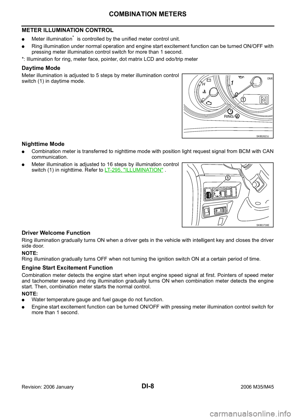
Meter illumination is adjusted to 5 steps by meter illumination control
switch (1) in daytime mode.
Nighttime Mode
Combination meter is transferred to nighttime mode with position light request signal from BCM with CAN
communication.
Meter illumination is adjusted to 16 steps by illumination control
switch (1) in nighttime. Refer to LT- 2 9 5 , "
ILLUMINATION" .
Driver Welcome Function
Ring illumination gradually turns ON when a driver gets in the vehicle with intelligent key and closes the driver
side door.
NOTE:
Ring illumination gradually turns OFF when not turning the ignition switch ON at a certain period of time.
Engine Start Excitement Function
Combination meter detects the engine start when input engine speed signal at first. Pointers of speed meter
and tachometer sweep and ring illumination gradually turns ON when combination meter detects the engine
start. Then, combination meter starts the normal control.
NOTE:
Water temperature gauge and fuel gauge do not function.
Engine start excitement function can be turned ON/OFF with pressing meter illumination control switch for
more than 1 second.
SKIB2623J
SKIB3738E
Page 1442 of 5621

COMBINATION METERS
DI-9
C
D
E
F
G
H
I
J
L
MA
B
DI
Revision: 2006 January2006 M35/M45
FA I L - S A F E
Combination meter performs fail-safe operation when unified meter and A/C amp. communication is malfunc-
tion.
Solution for communication error between the unified meter & A/C amp. and combination meter
Function Specifications
Speedometer
Reset to zero by suspending communication. Tachometer
Fuel gauge
Water temperature gauge
Illumination control Meter illumination When suspending communication, change to nighttime mode.
Dot matrix LCDPush engine starter
The display turns off by suspending communication. A/T position
ICC system
Buzzer The buzzer turns off by suspending communication.
Warning lamp/indicator lampABS warning lamp
The lamp turns on by suspending communication. Brake warning lamp
CRUISE warning lamp
VDC OFF indicator lamp
SLIP indicator lamp
A/T CHECK warning lamp
The lamp turns off by suspending communication. AWD warning lamp
Oil pressure warning lamp
Door warning lamp
Malfunction indicator lamp
CRUISE indicator lamp
SET indicator lamp
Low tire pressure warning lamp
AFS OFF indicator lamp
Front fog indicator lamp
High beam indicator
Turn signal indicator lamp
Key warning lamp
Page 1466 of 5621

UNIFIED METER AND A/C AMP
DI-33
C
D
E
F
G
H
I
J
L
MA
B
DI
Revision: 2006 January2006 M35/M45
DATA MONITOR
Operation Procedure
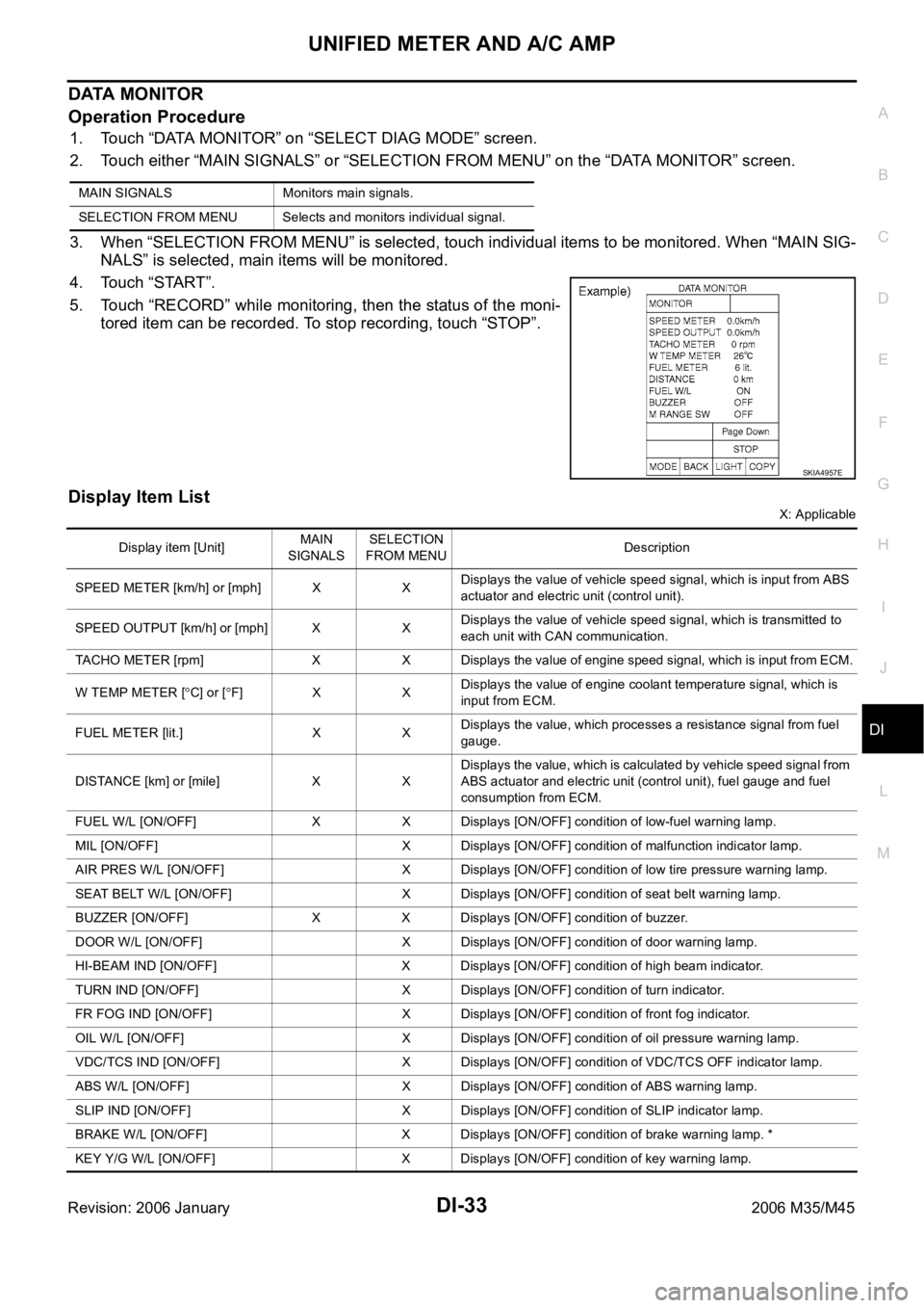
1. Touch “DATA MONITOR” on “SELECT DIAG MODE” screen.
2. Touch either “MAIN SIGNALS” or “SELECTION FROM MENU” on the “DATA MONITOR” screen.
3. When “SELECTION FROM MENU” is selected, touch individual items to be monitored. When “MAIN SIG-
NALS” is selected, main items will be monitored.
4. Touch “START”.
5. Touch “RECORD” while monitoring, then the status of the moni-
tored item can be recorded. To stop recording, touch “STOP”.
Display Item List
X: Applicable MAIN SIGNALS Monitors main signals.
SELECTION FROM MENU Selects and monitors individual signal.
SKIA4957E
Display item [Unit]MAIN
SIGNALSSELECTION
FROM MENUDescription
SPEED METER [km/h] or [mph] X XDisplays the value of vehicle speed signal, which is input from ABS
actuator and electric unit (control unit).
SPEED OUTPUT [km/h] or [mph] X XDisplays the value of vehicle speed signal, which is transmitted to
each unit with CAN communication.
TACHO METER [rpm] X X Displays the value of engine speed signal, which is input from ECM.
W TEMP METER [
C] or [F] X XDisplays the value of engine coolant temperature signal, which is
input from ECM.
FUEL METER [lit.] X XDisplays the value, which processes a resistance signal from fuel
gauge.
DISTANCE [km] or [mile] X XDisplays the value, which is calculated by vehicle speed signal from
ABS actuator and electric unit (control unit), fuel gauge and fuel
consumption from ECM.
FUEL W/L [ON/OFF] X X Displays [ON/OFF] condition of low-fuel warning lamp.
MIL [ON/OFF] X Displays [ON/OFF] condition of malfunction indicator lamp.
AIR PRES W/L [ON/OFF] X Displays [ON/OFF] condition of low tire pressure warning lamp.
SEAT BELT W/L [ON/OFF] X Displays [ON/OFF] condition of seat belt warning lamp.
BUZZER [ON/OFF] X X Displays [ON/OFF] condition of buzzer.
DOOR W/L [ON/OFF] X Displays [ON/OFF] condition of door warning lamp.
HI-BEAM IND [ON/OFF] X Displays [ON/OFF] condition of high beam indicator.
TURN IND [ON/OFF] X Displays [ON/OFF] condition of turn indicator.
FR FOG IND [ON/OFF] X Displays [ON/OFF] condition of front fog indicator.
OIL W/L [ON/OFF] X Displays [ON/OFF] condition of oil pressure warning lamp.
VDC/TCS IND [ON/OFF] X Displays [ON/OFF] condition of VDC/TCS OFF indicator lamp.
ABS W/L [ON/OFF] X Displays [ON/OFF] condition of ABS warning lamp.
SLIP IND [ON/OFF] X Displays [ON/OFF] condition of SLIP indicator lamp.
BRAKE W/L [ON/OFF] X Displays [ON/OFF] condition of brake warning lamp. *
KEY Y/G W/L [ON/OFF] X Displays [ON/OFF] condition of key warning lamp.
Page 1494 of 5621

WARNING CHIME
DI-61
C
D
E
F
G
H
I
J
L
MA
B
DI
Revision: 2006 January2006 M35/M45
IGNITION KEY WARNING CHIME (WITH INTELLIGENT KEY)
Refer to BL-55, "WARNING FUNCTION" in intelligent key system.
LIGHT WARNING CHIME
With ignition switch in OFF or ACC position, driver door open, and lighting switch in 1ST or 2ND position, the
light warning chime will sound.
BCM detects ignition switch in OFF or ACC position, front door switch (driver side) ON, and lighting switch
in 1ST or 2ND position. And then transmits buzzer output signal (light warning chime) to unified meter and
A/C amp. with CAN communication line.
Unified meter and A/C amp. transmits buzzer output signal (light warning chime) to combination meter
with communication line.
When combination meter receives buzzer output signal (light warning chime), it sounds the buzzer.
NOTE:
For further details of combination switch, refer to BCS-3, "
COMBINATION SWITCH READING FUNCTION" .
SEAT BELT WARNING CHIME
With ignition switch turned ON and driver seat belt unfastened, seat belt warning chime will sound for approxi-
mately 6 seconds.
BCM receives seat belt buckle switch signal [seat belt buckle switch (driver side) ON] from unified meter
and A/C amp. with CAN communication line.
BCM detects ignition switch turned ON and seat belt buckle switch (driver side) ON. And then transmits
buzzer output signal (seat belt warning chime) to unified meter and A/C amp. with CAN communication
line.
Unified meter and A/C amp. transmits buzzer output signal (seat belt warning chime) to combination
meter with communication line.
When combination meter receives buzzer output signal (seat belt warning chime), it sounds the buzzer.
SKIB3858E
SKIB3859E
Page 1501 of 5621

DI-68
WARNING CHIME
Revision: 2006 January2006 M35/M45
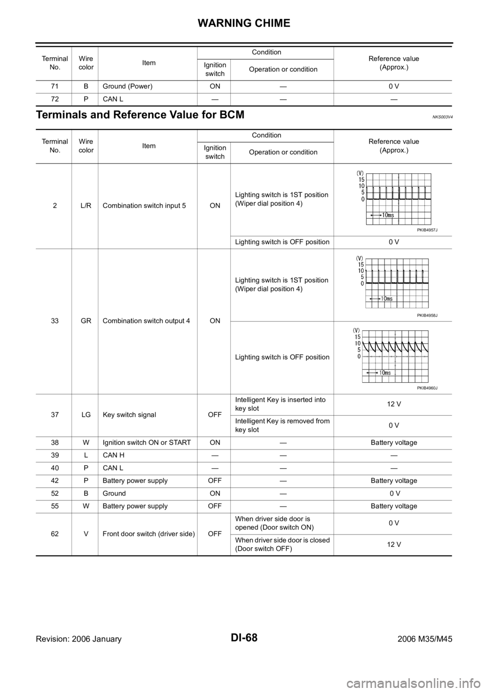
Terminals and Reference Value for BCMNKS003V4
71 B Ground (Power) ON — 0 V
72 P CAN L — — — Te r m i n a l
No.Wire
colorItemCondition
Reference value
(Approx.) Ignition
switchOperation or condition
Te r m i n a l
No.Wire
colorItemCondition
Reference value
(Approx.) Ignition
switchOperation or condition
2 L/R Combination switch input 5 ONLighting switch is 1ST position
(Wiper dial position 4)
Lighting switch is OFF position 0 V
33 GR Combination switch output 4 ONLighting switch is 1ST position
(Wiper dial position 4)
Lighting switch is OFF position
37 LG Key switch signal OFFIntelligent Key is inserted into
key slot12 V
Intelligent Key is removed from
key slot0 V
38 W Ignition switch ON or START ON — Battery voltage
39 L CAN H — — —
40 P CAN L — — —
42 P Battery power supply OFF — Battery voltage
52 B Ground ON — 0 V
55 W Battery power supply OFF — Battery voltage
62 V Front door switch (driver side) OFFWhen driver side door is
opened (Door switch ON)0 V
When driver side door is closed
(Door switch OFF)12 V
PKIB4957J
PKIB4958J
PKIB4960J
Page 1503 of 5621

DI-70
WARNING CHIME
Revision: 2006 January2006 M35/M45
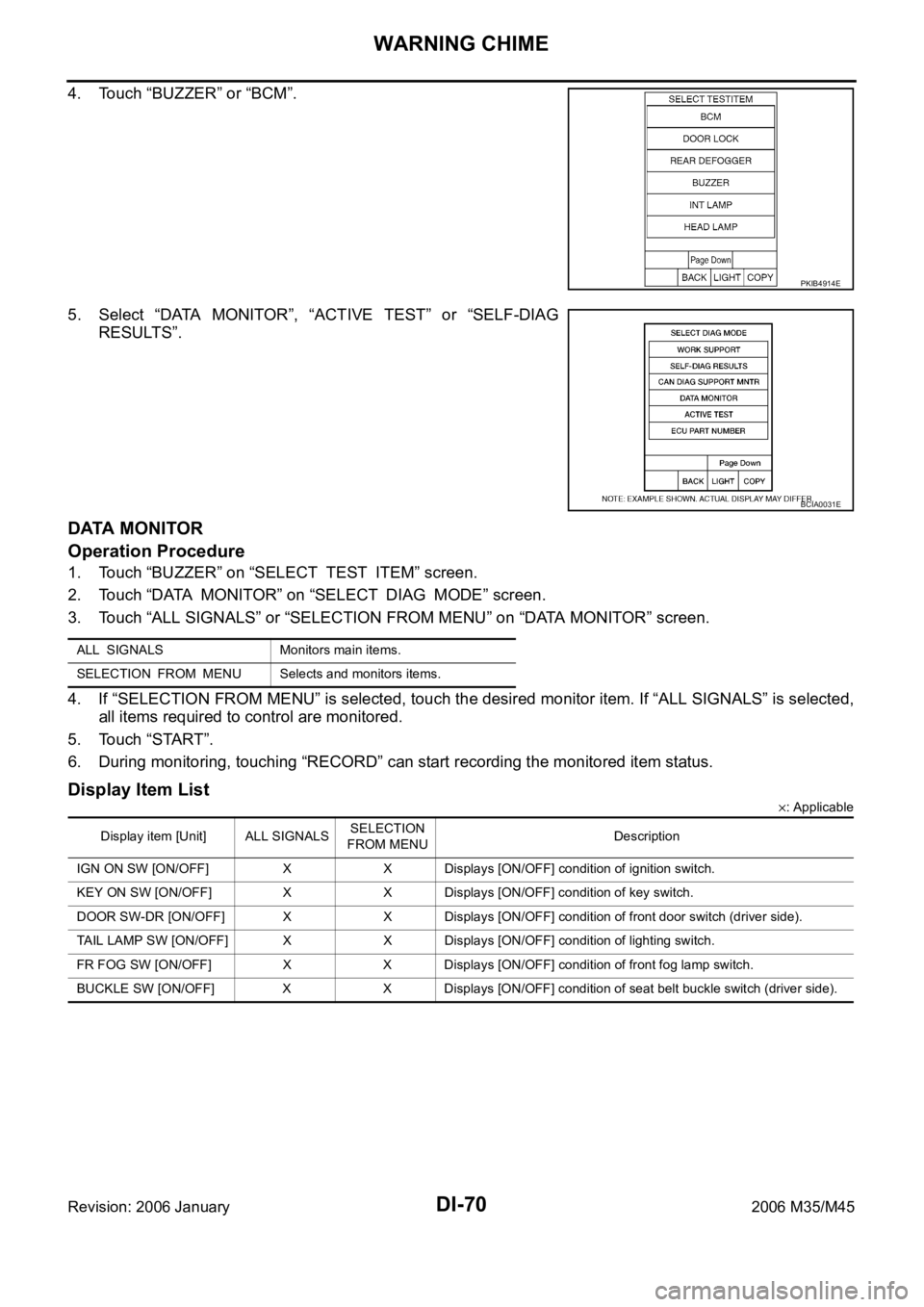
4. Touch “BUZZER” or “BCM”.
5. Select “DATA MONITOR”, “ACTIVE TEST” or “SELF-DIAG
RESULTS”.
DATA MONITOR
Operation Procedure
1. Touch “BUZZER” on “SELECT TEST ITEM” screen.
2. Touch “DATA MONITOR” on “SELECT DIAG MODE” screen.
3. Touch “ALL SIGNALS” or “SELECTION FROM MENU” on “DATA MONITOR” screen.
4. If “SELECTION FROM MENU” is selected, touch the desired monitor item. If “ALL SIGNALS” is selected,
all items required to control are monitored.
5. Touch “START”.
6. During monitoring, touching “RECORD” can start recording the monitored item status.
Display Item List
: Applicable
PKIB4914E
BCIA0031E
ALL SIGNALS Monitors main items.
SELECTION FROM MENU Selects and monitors items.
Display item [Unit] ALL SIGNALSSELECTION
FROM MENUDescription
IGN ON SW [ON/OFF] X X Displays [ON/OFF] condition of ignition switch.
KEY ON SW [ON/OFF] X X Displays [ON/OFF] condition of key switch.
DOOR SW-DR [ON/OFF] X X Displays [ON/OFF] condition of front door switch (driver side).
TAIL LAMP SW [ON/OFF] X X Displays [ON/OFF] condition of lighting switch.
FR FOG SW [ON/OFF] X X Displays [ON/OFF] condition of front fog lamp switch.
BUCKLE SW [ON/OFF] X X Displays [ON/OFF] condition of seat belt buckle switch (driver side).