Page 1163 of 5621

BL-224
VEHICLE SECURITY (THEFT WARNING) SYSTEM
Revision: 2006 January2006 M35/M45
VEHICLE SECURITY SYSTEM ALARM OPERATION
The vehicle security system is triggered by
opening a door
opening the trunk
opening the hood
detection of battery disconnect and connect.
The vehicle security system will be triggered once the system is in armed phase,
when BCM receives a ground signal at terminals 12 (passenger side door), 13 (rear RH door), 57 (trunk), 62
(driver side door), 63 (rear LH door), or receives a signal from the IPDM E/R (hood switch).
When the vehicle security system is triggered,
ground is supplied intermittently to both headlamp relay and horn relay.
When headlamp relay and horn relay are energized, then power is supplied to headlamps (LH and RH) and
horns (HIGH and LOW).
The headlamps flash and the horn sounds intermittently.
The alarm automatically turns off after 50 seconds, but will reactivate if the vehicle is tampered with again.
VEHICLE SECURITY SYSTEM DEACTIVATION
To deactivate the vehicle security system, a door or the trunk must be unlocked with the key, Intelligent Key.
When the key is used to unlock a door, BCM terminal 22 receives signal
from the power window main switch (door lock and unlock switch) terminal 14.
When the BCM receives either one of these signals or unlock signal from key cylinder switch or Intelligent Key,
the vehicle security system is deactivated. (Disarmed phase)
PANIC ALARM OPERATION
Intelligent Key system may or may not operate vehicle security system (horn and headlamps) as required.
When the Intelligent Key system is triggered, ground is supplied intermittently to both headlamp relay and horn
relay.
When headlamp relay and horn relay are energized, then power is supplied to headlamps (LH and RH) and
horns (HIGH and LOW).
The headlamp flashes and the horn sounds intermittently.
The alarm automatically turns off after 25 seconds or when BCM receives any signal from Intelligent Key.
CAN Communication System DescriptionNIS001ZV
CAN (Controller Area Network) is a serial communication line for real time application. It is an on-vehicle mul-
tiplex communication line with high data communication speed and excellent error detection ability. Many elec-
tronic control units are equipped onto a vehicle, and each control unit shares information and links with other
control units during operation (not independent). In CAN communication, control units are connected with 2
communication lines (CAN H line, CAN L line) allowing a high rate of information transmission with less wiring.
Each control unit transmits/receives data but selectively reads required data only.
CAN Communication UnitNIS001ZW
Refer to LAN-34, "CAN COMMUNICATION" .
Page 1171 of 5621

BL-232
VEHICLE SECURITY (THEFT WARNING) SYSTEM
Revision: 2006 January2006 M35/M45
Terminals and Reference Value of BCMNIS001ZZ
Terminals and Reference Value of IPDM E/RNIS00200
Terminal Wire color Item ConditionVoltage [V]
(Approx.)
11 V Power supply (ACC) Ignition switch (ACC or ON position) Battery voltage
12 PFront door switch
passenger side signalON (Open)
OFF (Closed) 0 Battery voltage
13 O/L Rear door switch RH signal ON (Open)
OFF (Closed) 0 Battery voltage
22 G Power window serial linkIgnition switch ON or power window
timer operating
23 W/V Security indicator lamp Goes off
Illuminates Battery voltage 0
37 LG Key switch signalKey inserted in key slot
key
removed from key slotBattery voltage 0
39 L CAN-H — —
40 P CAN-L — —
42 P Power source (fuse) — Battery voltage
52 B Ground — 0
55 W Battery power supply (fusible link) — Battery voltage
56 W Trunk lid key cylinder switch Neutral
Unlock Battery voltage 0
57 SB Trunk room lamp switch signal ON (Open)
OFF (Closed) 0 Battery voltage
62 VFront door switch
driver side signalON (Open)
OFF (Closed) 0 Battery voltage
63 R/G Rear door switch LH signal ON (Open)
OFF (Closed) 0 Battery voltage
PIIA2344J
Terminal Wire color Item ConditionVoltage [V]
(Approx.)
38 B Ground (power) — 0
48 G/B Horn relay control signalPanic alarm is operating 0
Other than above Battery voltage
49 L CAN-H — —
50 P CAN-L — —
51 B Ground (signal) — 0
60 LG/B Hood switch signal ON (Open)
OFF (closed) 0 Battery voltage
Page 1177 of 5621
BL-238
VEHICLE SECURITY (THEFT WARNING) SYSTEM
Revision: 2006 January2006 M35/M45
Diagnostic Procedure 1NIS00205
DOOR SWITCH CHECK
1. CHECK DOOR SWITCH INPUT SIGNAL
With CONSULT-II
Check door switches (“DOOR SW-DR”, “DOOR SW-AS”, “DOOR SW-RL” and “DOOR SW-RR”) in “DATA
MONITOR” mode with CONSULT-II.
Without CONSULT-II
1. Turn ignition switch OFF.
2. Check voltage between BCM connector and ground.
OK or NG
OK >> Door switch circuit is OK.
NG >> GO TO 2.
Monitor item Condition
DOOR SW-DR
CLOSE
OPEN: OFF ON DOOR SW-AS
DOOR SW-RL
DOOR SW-RR
PIIA6469E
Terminals
Door conditionVoltage (V)
(Approx.) (+)
(–)
BCM
connectorTerminal
M112
GroundFront
passenger
sideOPEN 0
CLOSE Battery voltage
13Rear RH
sideOPEN 0
CLOSE Battery voltage
M362 Driver sideOPEN 0
CLOSE Battery voltage
63Rear LH
sideOPEN 0
CLOSE Battery voltage
PIIB6324E
Page 1179 of 5621
BL-240
VEHICLE SECURITY (THEFT WARNING) SYSTEM
Revision: 2006 January2006 M35/M45
4. CHECK BCM OUTPUT SIGNAL
1. Connect BCM connector.
2. Check voltage between BCM connector and ground.
OK or NG
OK >> Check the condition of harness and connector.
NG >> Replace BCM.
Terminals
Voltage (V)
(Approx.) (+)
(–)
BCM connector Terminal
M112
Ground Battery voltage 13
M362
63
PIIB6324E
Page 1180 of 5621

VEHICLE SECURITY (THEFT WARNING) SYSTEM
BL-241
C
D
E
F
G
H
J
K
L
MA
B
BL
Revision: 2006 January2006 M35/M45
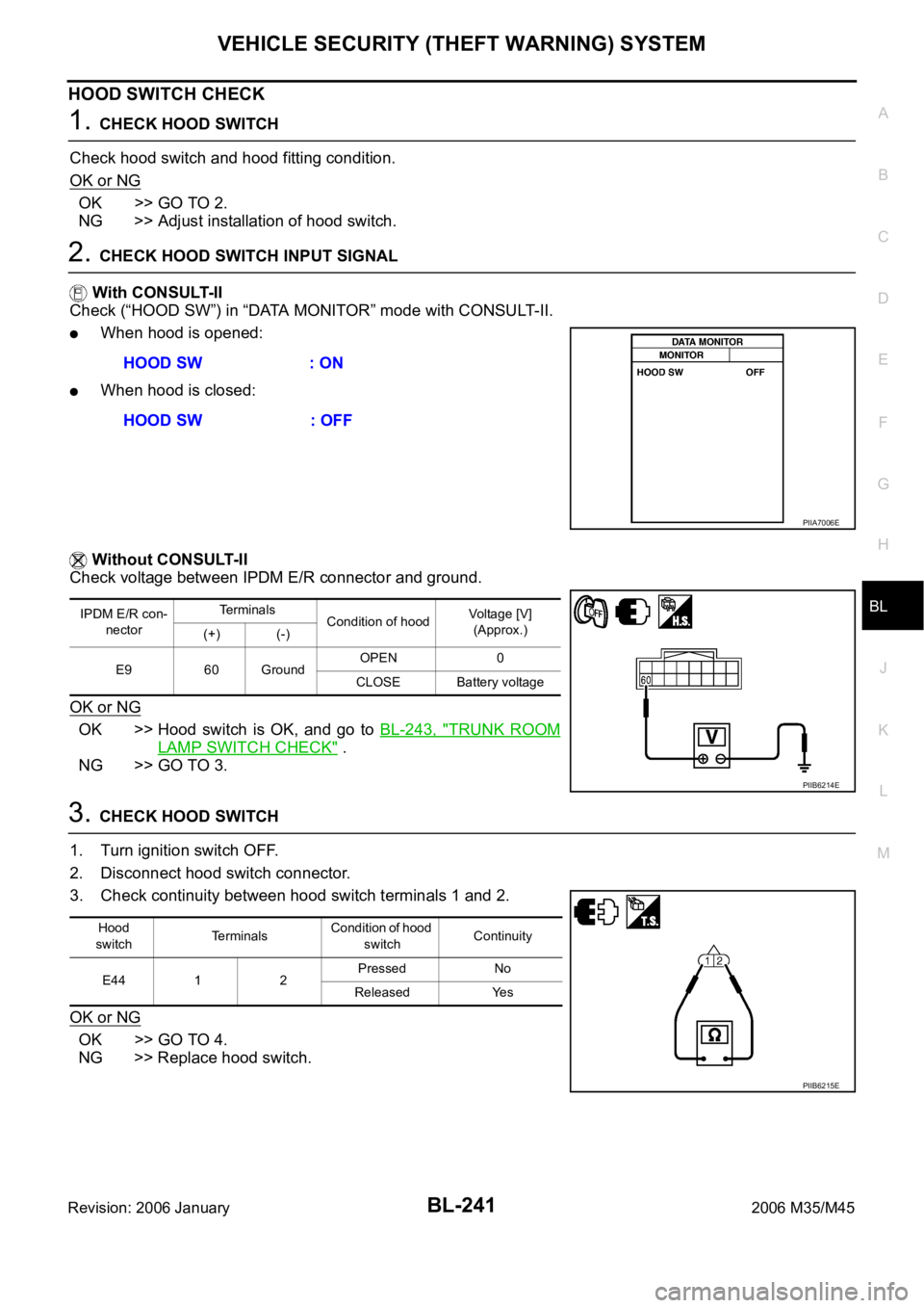
HOOD SWITCH CHECK
1. CHECK HOOD SWITCH
Check hood switch and hood fitting condition.
OK or NG
OK >> GO TO 2.
NG >> Adjust installation of hood switch.
2. CHECK HOOD SWITCH INPUT SIGNAL
With CONSULT-II
Check (“HOOD SW”) in “DATA MONITOR” mode with CONSULT-II.
When hood is opened:
When hood is closed:
Without CONSULT-II
Check voltage between IPDM E/R connector and ground.
OK or NG
OK >> Hood switch is OK, and go to BL-243, "TRUNK ROOM
LAMP SWITCH CHECK" .
NG >> GO TO 3.
3. CHECK HOOD SWITCH
1. Turn ignition switch OFF.
2. Disconnect hood switch connector.
3. Check continuity between hood switch terminals 1 and 2.
OK or NG
OK >> GO TO 4.
NG >> Replace hood switch.HOOD SW : ON
HOOD SW : OFF
PIIA7006E
IPDM E/R con-
nectorTe r m i n a l s
Condition of hoodVoltage [V]
(Approx.)
(+) (-)
E9 60 GroundOPEN 0
CLOSE Battery voltage
PIIB6214E
Hood
switchTerminalsCondition of hood
switchContinuity
E44 1 2Pressed No
Released Yes
PIIB6215E
Page 1182 of 5621
VEHICLE SECURITY (THEFT WARNING) SYSTEM
BL-243
C
D
E
F
G
H
J
K
L
MA
B
BL
Revision: 2006 January2006 M35/M45
TRUNK ROOM LAMP SWITCH CHECK
1. CHECK TRUNK ROOM LAMP SWITCH INPUT SIGNAL
With CONSULT-II
Check (“TRUNK SW”) in “DATA MONITOR” mode with CONSULT-II.
Without CONSULT-II
1. Turn ignition switch OFF.
2. Check voltage between BCM connector and ground.
OK or NG
OK >> Trunk room lamp switch circuit is OK.
NG >> GO TO 2.
2. CHECK TRUNK ROOM LAMP SWITCH
1. Turn ignition switch OFF.
2. Disconnect trunk lid lock assembly connector.
3. Check trunk room lamp switch.
OK or NG
OK >> GO TO 3.
NG >> Replace trunk room lamp switch.
Monitor item Condition
TRUNK SWOPEN : ON
CLOSE : OFF
PIIB1362E
Terminals
Trunk
conditionVoltage (V)
(Approx.) (+)
(–)
BCM connector Terminal
M3 57 GroundOPEN 0
CLOSE Battery voltage
PIIB6326E
Terminal
Trunk condition Continuity
Trunk room lamp switch
12OPEN Yes
CLOSE No
PIIB6327E
Page 1183 of 5621

BL-244
VEHICLE SECURITY (THEFT WARNING) SYSTEM
Revision: 2006 January2006 M35/M45
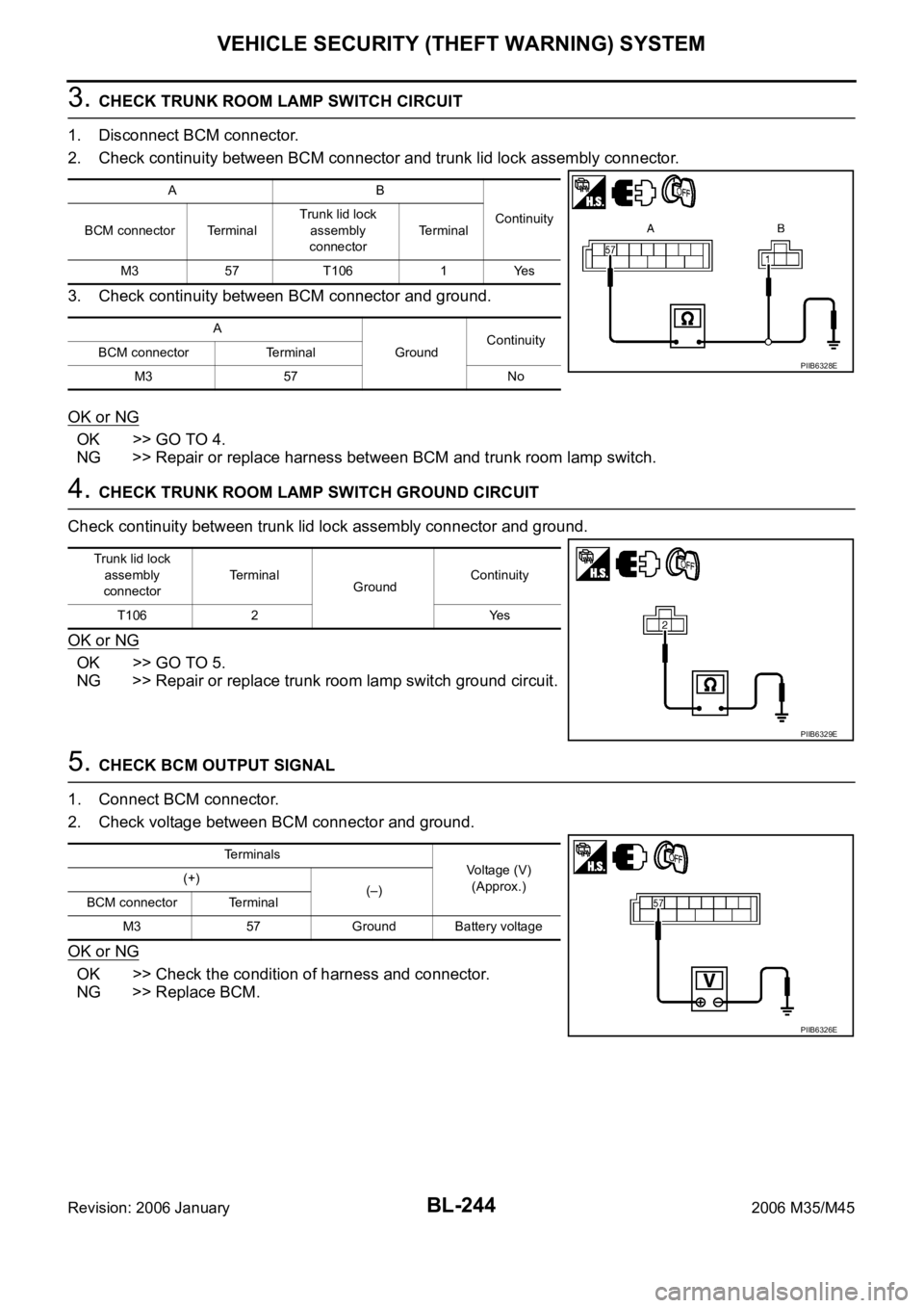
3. CHECK TRUNK ROOM LAMP SWITCH CIRCUIT
1. Disconnect BCM connector.
2. Check continuity between BCM connector and trunk lid lock assembly connector.
3. Check continuity between BCM connector and ground.
OK or NG
OK >> GO TO 4.
NG >> Repair or replace harness between BCM and trunk room lamp switch.
4. CHECK TRUNK ROOM LAMP SWITCH GROUND CIRCUIT
Check continuity between trunk lid lock assembly connector and ground.
OK or NG
OK >> GO TO 5.
NG >> Repair or replace trunk room lamp switch ground circuit.
5. CHECK BCM OUTPUT SIGNAL
1. Connect BCM connector.
2. Check voltage between BCM connector and ground.
OK or NG
OK >> Check the condition of harness and connector.
NG >> Replace BCM.
AB
Continuity
BCM connector TerminalTrunk lid lock
assembly
connectorTerminal
M3 57 T106 1 Yes
A
GroundContinuity
BCM connector Terminal
M3 57 No
PIIB6328E
Trunk lid lock
assembly
connectorTerminal
GroundContinuity
T106 2 Yes
PIIB6329E
Terminals
Voltage (V)
(Approx.) (+)
(–)
BCM connector Terminal
M3 57 Ground Battery voltage
PIIB6326E
Page 1184 of 5621

VEHICLE SECURITY (THEFT WARNING) SYSTEM
BL-245
C
D
E
F
G
H
J
K
L
MA
B
BL
Revision: 2006 January2006 M35/M45
Diagnostic Procedure 2NIS00206
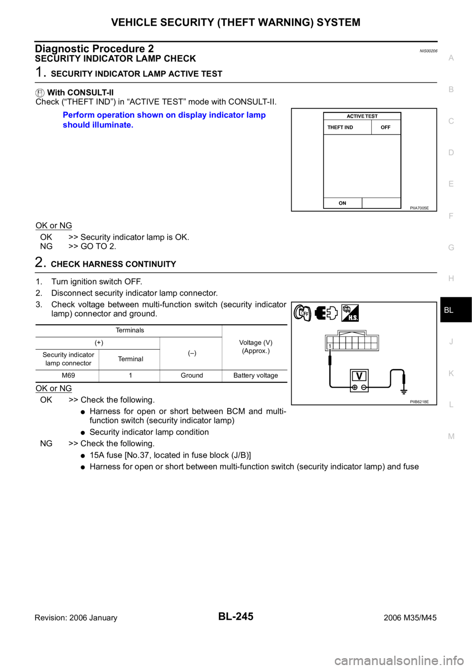
SECURITY INDICATOR LAMP CHECK
1. SECURITY INDICATOR LAMP ACTIVE TEST
With CONSULT-II
Check (“THEFT IND”) in “ACTIVE TEST” mode with CONSULT-II.
OK or NG
OK >> Security indicator lamp is OK.
NG >> GO TO 2.
2. CHECK HARNESS CONTINUITY
1. Turn ignition switch OFF.
2. Disconnect security indicator lamp connector.
3. Check voltage between multi-function switch (security indicator
lamp) connector and ground.
OK or NG
OK >> Check the following.
Harness for open or short between BCM and multi-
function switch (security indicator lamp)
Security indicator lamp condition
NG >> Check the following.
15A fuse [No.37, located in fuse block (J/B)]
Harness for open or short between multi-function switch (security indicator lamp) and fuse Perform operation shown on display indicator lamp
should illuminate.
PIIA7005E
Terminals
Voltage (V)
(Approx.) (+)
(–)
Security indicator
lamp connectorTerminal
M69 1 Ground Battery voltage
PIIB6218E