2006 INFINITI M35 flat tire
[x] Cancel search: flat tirePage 5411 of 5621

SRS-50
COLLISION DIAGNOSIS
Revision: 2006 January2006 M35/M45
COLLISION DIAGNOSISPFP:00015
For Frontal CollisionNHS0009L
To repair the SRS, perform the following steps.
When SRS (except the front side air bag and side curtain air bag modules) is activated in a collision:
1. Replace the diagnosis sensor unit.
2. Remove the air bag modules (except the front side air bag modules and side curtain air bag modules),
crash zone sensor assembly, bracket and seat belt pre-tensioner assemblies.
3. Check the SRS components using the table below:
–Replace any SRS components showing visible signs of damage (dents, cracks and deformation).
4. Install new air bag modules (except the front side air bag modules and side curtain air bag modules) crash
zone sensor assembly, bracket and seat belt pre-tensioner assemblies.
5. Conduct self-diagnosis using CONSULT-II or “AIR BAG” warning lamp. Refer to SRS-19, "
SRS Operation
Check" for details. Ensure entire SRS operates properly.
When SRS is not activated in a collision:
1. Check the SRS components using the table below:
–Replace any SRS components showing visible signs of damage (dents, cracks and deformation).
2. Conduct self-diagnosis using CONSULT-II or “AIR BAG” warning lamp. Refer to SRS-19, "
SRS Operation
Check" for details. Ensure entire SRS operates properly.
When only one front air bag module is activated in a collision:
1. Replace the following components:
–Diagnosis sensor unit
–Crash zone sensor
–Activated front air bag and seat belt pre-tensioner.
2. Check the other SRS components using the table below (Refer to “SRS is NOT activated”).
–Replace any SRS components showing visible signs of damage (dents, cracks and deformation).
3. Conduct self-diagnosis using CONSULT-II or “AIR BAG” warning lamp. Refer to SRS-19, "
SRS Operation
Check" for details. Ensure entire SRS operates properly.
Only one front air bag may inflate a crash, depending on the crash severity and whether the front occupants
are belted or unbelted. This does not indicate improper performance of the system. Perform self-diagnosis to
make sure the entire SRS operates properly.
SRS INSPECTION (FOR FRONTAL COLLISION)
Part SRS is activated SRS is NOT activated
Driver airbag
moduleIf the Driver airbag has deployed:
REPLACE.
Install with new fasteners.If the Driver air bag has NOT been activated:
[same text as in current manual]
Passenger front
airbag moduleIf the Passenger front airbag has deployed:
REPLACE.
Install with new fasteners.If the Passenger front air bag has NOT been activated:
[same text as in current manual]
Crash zone
sensorIf any of the front airbags or seat belt pre-
tensionsers have been activated:
REPLACE the crash zone sensor and bracket
with new fasteners. If the front airbags or seat belt pre-tensionsers have NOT
been activated:
[same text as in current manual]
Seat belt pre-ten-
sioner assembliesIf the driver or passenger Seat belt pre-ten-
sioner has been activated:
REPLACE the seat belt pre-tensioner
assemblies with new fasteners. If the pre-tensioners have NOT been activated:
[same text as in current manual]
Diagnosis sensor
unitIf any of the SRS components have been
activated:
REPLACE the Diagnosis sensor unit.
Install with new fasteners.If none of the SRS components have been activated:
[same text as in current manual]
Page 5531 of 5621

WT-6
ROAD WHEEL
Revision: 2006 January2006 M35/M45
ROAD WHEELPFP:40300
InspectionNES000JO
ALUMINUM WHEEL
1. Check tires for wear and improper inflation.
2. Check wheels for deformation, cracks and other damage. If deformed, remove wheel and check wheel
runout.
a. Remove tire from aluminum wheel and mount on a tire balance machine.
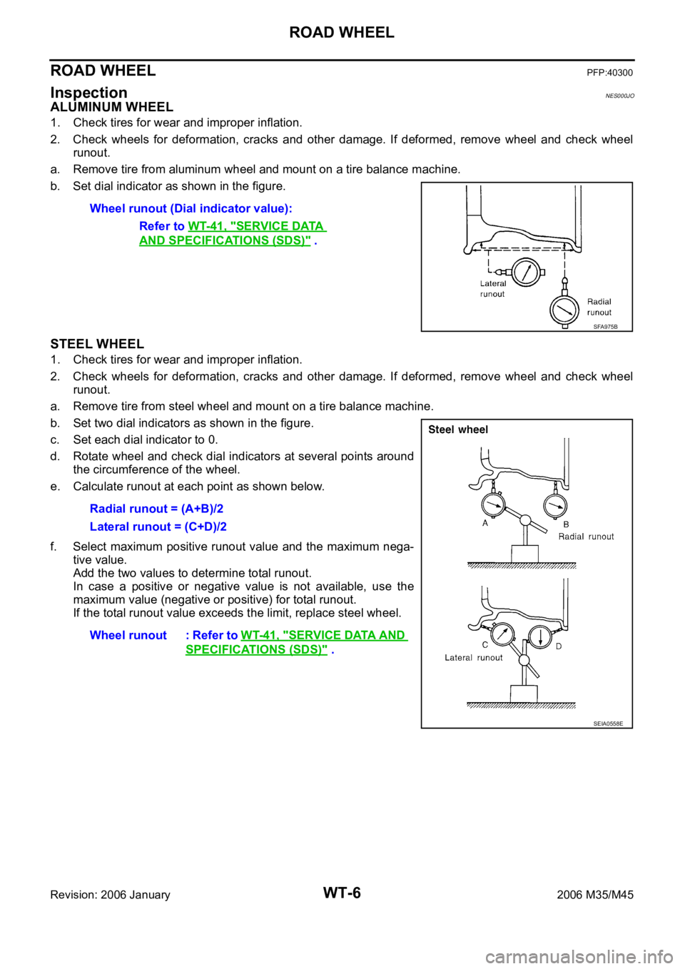
b. Set dial indicator as shown in the figure.
STEEL WHEEL
1. Check tires for wear and improper inflation.
2. Check wheels for deformation, cracks and other damage. If deformed, remove wheel and check wheel
runout.
a. Remove tire from steel wheel and mount on a tire balance machine.
b. Set two dial indicators as shown in the figure.
c. Set each dial indicator to 0.
d. Rotate wheel and check dial indicators at several points around
the circumference of the wheel.
e. Calculate runout at each point as shown below.
f. Select maximum positive runout value and the maximum nega-
tive value.
Add the two values to determine total runout.
In case a positive or negative value is not available, use the
maximum value (negative or positive) for total runout.
If the total runout value exceeds the limit, replace steel wheel. Wheel runout (Dial indicator value):
Refer to WT-41, "
SERVICE DATA
AND SPECIFICATIONS (SDS)" .
SFA975B
Radial runout = (A+B)/2
Lateral runout = (C+D)/2
Wheel runout : Refer to WT-41, "
SERVICE DATA AND
SPECIFICATIONS (SDS)" .
SEIA0558E
Page 5535 of 5621

WT-10
LOW TIRE PRESSURE WARNING SYSTEM
Revision: 2006 January2006 M35/M45
RECEIVER
The receiver receives the air pressure signal transmitted by the transmitter in each wheel.
LOW TIRE PRESSURE WARNING CONTROL UNIT
The low tire pressure warning control unit (1) reads the air pressure
signal received by the receiver, and controls the low tire pressure
warning lamp and the buzzer operations. It also has a judgement
function to detect a system malfunction.
LOW TIRE PRESSURE WARNING LAMP
The combination meter receives tire pressure status from the low tire
pressure warning control unit using CAN communication. When a
low tire pressure condition is sensed by the low tire pressure control
unit, the combination meter low tire pressure warning lamp and
buzzer are activated.
Low Tire Pressure Warning Lamp Indication
*: Standard air pressure is for 230 kpa (2.3 kg/cm2 , 33 psi) vehicle. 1. Tire pressure receiver front 2. Tire pressure receiver rear A. Front wheel house
B. Rear wheel house
Refer to GI-11, "
Components" , for the symbols in the figure.
SEIA0649E
SEIA0650E
SEIA0434E
ConditionLow tire pressure warning
lampBuzzer
Less than 186 kPa
(1.86 kg/cm
2 , 27 psi) [Flat tire]*ON Sounds for 10 sec.
Low tire pressure warning system malfunction [Other diagnostic item]Warning lamp flashes 1 min,
then turns ONOFF
Page 5545 of 5621

WT-20
TROUBLE DIAGNOSES
Revision: 2006 January2006 M35/M45
ID REGISTRATION WITHOUT ACTIVATION TOOL
This procedure must be done after replacement of a tire pressure transmitter, low tire pressure warn-
ing control unit, or tire rotation.
CAUTION:
If CONSULT-II is used with no connection of CONSULT-II CONVERTER, malfunction might be detected
during self-diagnosis depending on control unit which performs CAN communication.
1. Turn ignition switch OFF.
2. Connect CONSULT-II and CONSULT-II CONVERTER to data link connector.
3. Turn ignition switch ON.
4. Touch “START (NISSAN BASED VHCL)” “AIR PRESSURE MONITOR”.
If “AIR PRESSURE MONITOR” is not displayed, print the “SELECT SYSTEM” screen. Then refer to
LAN-7, "
Precautions When Using CONSULT-II" .
NOTE:
Just after starting engine, or turning ignition switch ON, it may not be displayed even if “START (NIS-
SAN BASED VHCL)” is touched. In this case, reconnect CONSULT-II and CONSULT-II CONVERTER.
5. Touch “WORK SUPPORT” on “SELECT DIAG MODE” screen.
6. Touch “ID REGIST” on “SELECT WORK ITEM”.
7. Adjust the tire pressure to the values shown in the table below for ID registration, and drive the vehicle at
40 km/h (25 MPH) or more for a few minutes.
8. After completing all ID registrations, press “END” to complete the procedure.
9. Inflate all tires to proper pressure. Refer to WT-41, "
SERVICE DATA AND SPECIFICATIONS (SDS)" .
Tire position
Tire pressure kPa (kg/cm2 , psi)
Front
Left 240 (2.4, 34)
Front
Right 220 (2.2, 31)
Rear
Right 200 (2.0, 29)
Rear
Left 180 (1.8, 26)
Activation tire position CONSULT-II
Front LH
“YET”
“DONE” Front RH
Rear RH
Rear LH
Page 5547 of 5621

WT-22
TROUBLE DIAGNOSES
Revision: 2006 January2006 M35/M45
WORK SUPPORT MODE
Operation Procedure
1. Perform “CONSULT-II Start Procedure”. Refer to GI-39, "CONSULT-II Start Procedure" .
2. Perform the “ID Regist”. Refer to WT-19, "
ID Registration Procedure" .
SELF-DIAG RESULT MODE
Operation Procedure
1. Perform “CONSULT-II Start Procedure”. Refer to GI-39, "CONSULT-II Start Procedure" .
2. The self-diagnostic results are displayed. (Touch “PRINT” to print out the self-diagnostic results if neces-
sary.) Check low tire pressure warning lamp if “NO FAILURE” is displayed.
3. Perform the appropriate inspection from the display item list, and repair or replace the malfunctioning
component. Refer to WT-22, "
Display Item List" .
Display Item List
NOTE:
Before performing the self-diagnosis, be sure to register the ID, or else the actual malfunction location may be different from that dis-
played on CONSULT-II.DTC Diagnostic item Diagnostic item is detected when ꞏꞏꞏ Check items
C1700 FLAT_TIRE_FLFront-left tire pressure drops to * kPa (* kg/cm
2 , * psi) or less.
(Notice)
— C1701 FLAT_TIRE_FRFront-right tire pressure drops to * kPa (* kg/cm
2 , * psi) or less.
(Notice)
C1702 FLAT_TIRE_RRRear-right tire pressure drops to * kPa (* kg/cm
2 , * psi) or less.
(Notice)
C1703 FLAT_TIRE_RLRear-left tire pressure drops to * kPa (* kg/cm
2 , * psi) or less.
(Notice)
C1708 [NO_DATA]_FL Data from front-left transmitter cannot be received.
WT-30
C1709 [NO_DATA]_FR Data from front-right transmitter cannot be received.
C1710 [NO_DATA]_RR Data from rear-right transmitter cannot be received.
C1711 [NO_DATA]_RL Data from rear-left transmitter cannot be received.
C1716 [PRESSDATA_ERR]_FL Air pressure data from front-left transmitter is malfunctioning.
WT-32
C1717 [PRESSDATA_ERR]_FR Air pressure data from front-right transmitter is malfunctioning.
C1718 [PRESSDATA_ERR]_RR Air pressure data from rear-right transmitter is malfunctioning.
C1719 [PRESSDATA_ERR]_RL Air pressure data from rear-left transmitter is malfunctioning.
C1720 [CODE_ERROR]_FL Function code data from front-left transmitter is malfunctioning.
WT-32
C1721 [CODE_ERROR]_FR Function code data from front-right transmitter is malfunctioning.
C1722 [CODE_ERROR]_RR Function code data from rear-right transmitter is malfunctioning.
C1723 [CODE_ERROR]_RL Function code data from rear-left transmitter is malfunctioning.
C1724 [BATT_VOLT_LOW]_FL Battery voltage of front-left transmitter drops.
WT-33
C1725 [BATT_VOLT_LOW]_FR Battery voltage of front-right transmitter drops.
C1726 [BATT_VOLT_LOW]_RR Battery voltage of rear-right transmitter drops.
C1727 [BATT_VOLT_LOW]_RL Battery voltage of rear-left transmitter drops.
C1728 RECEIVER_ID_NO_REG ID registration of receiver is not completed.WT-33
C1729 VHCL_SPEED_SIG_ERR Vehicle speed signal is error.WT-34
C1750 [RECEIVER_ERR]_FL Data from front-left receiver cannot be received.
WT-31
C1751 [RECEIVER_ERR]_FR Data from front-right receiver cannot be received.
C1752 [RECEIVER_ERR]_RR Data from rear-right receiver cannot be received.
C1753 [RECEIVER_ERR]_RL Data from rear-left receiver cannot be received.
U1000 CAN COMM CIRCUITWhen a control unit (except for low tire pressure) is not transmit-
ting or receiving CAN communication signal 2 seconds or less. WT-34
Page 5549 of 5621

WT-24
TROUBLE DIAGNOSES
Revision: 2006 January2006 M35/M45
LOW TIRE PRESSURE WARNING CONTROL UNIT PART NUMBER
Operation Procedure
1. Perform “CONSULT-II Start Procedure”. Refer to GI-39, "CONSULT-II Start Procedure" .
2. The part number described on low tire pressure warning control unit sticker is displayed.
Diagnosis Procedure with Warning Lamp Function (Without CONSULT-II)NES000K6
DESCRIPTION
During driving, the low tire pressure warning system receives the signal transmitted from the transmitter
installed in each wheel, and gives alarms when the tire pressure becomes low. The control unit (low tire pres-
sure warning control unit) of this system has pressure judgement and trouble diagnosis functions.
FUNCTION
When the low tire pressure warning system detects low inflation pressure or another unusual symptom, the
warning lamps in the combination meter comes on. To start the self-diagnostic results mode, ground terminal
of the tire pressure warning check connector. The malfunction location is indicated by the warning lamp flash-
ing and the buzzer sounds. Regarding location of tire pressure warning check connector, refer to PG-63,
"HARNESS" .
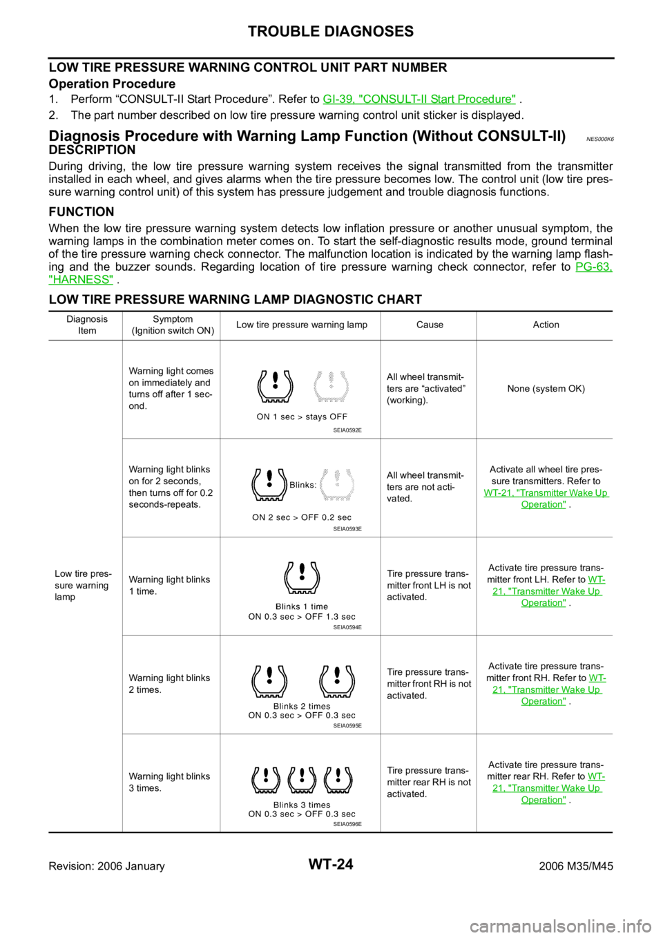
LOW TIRE PRESSURE WARNING LAMP DIAGNOSTIC CHART
Diagnosis
ItemSymptom
(Ignition switch ON)Low tire pressure warning lamp Cause Action
Low tire pres-
sure warning
lampWarning light comes
on immediately and
turns off after 1 sec-
ond.All wheel transmit-
ters are “activated”
(working).None (system OK)
Warning light blinks
on for 2 seconds,
then turns off for 0.2
seconds-repeats.All wheel transmit-
ters are not acti-
vated.Activate all wheel tire pres-
sure transmitters. Refer to
WT-21, "
Transmitter Wake Up
Operation" .
Warning light blinks
1 time.Tire pressure trans-
mitter front LH is not
activated.Activate tire pressure trans-
mitter front LH. Refer to WT-
21, "Transmitter Wake Up
Operation" .
Warning light blinks
2 times.Tire pressure trans-
mitter front RH is not
activated.Activate tire pressure trans-
mitter front RH. Refer to WT-
21, "Transmitter Wake Up
Operation" .
Warning light blinks
3 times.Tire pressure trans-
mitter rear RH is not
activated.Activate tire pressure trans-
mitter rear RH. Refer to WT-
21, "Transmitter Wake Up
Operation" .
SEIA0592E
SEIA0593E
SEIA0594E
SEIA0595E
SEIA0596E
Page 5553 of 5621

WT-28
TROUBLE DIAGNOSES
Revision: 2006 January2006 M35/M45
Trouble Diagnosis ChartNES000K9
SELF-DIAGNOSIS
NOTICE:
186 kPa (1.86 kg/cm2 , 27 psi): Standard air pressure is for 230 kpa (2.3 kg/cm2 , 33 psi) vehicles. Item
Reference Self-diagnosis function CONSULT-II
DTC (warning lamp blinks) Diagnosis item Diagnosis item
11Front-left tire pressure drops to * kPa
(* kg/cm
2 , * psi) or less. (Notice)FLAT_TIRE_FL
— 12Front-right tire pressure drops to * kPa
(* kg/cm
2 , * psi) or less. (Notice)FLAT_TIRE_FR
13Rear-right tire pressure drops to * kPa
(* kg/cm
2 , * psi) or less. (Notice)FLAT_TIRE_RR
14Rear-left tire pressure drops to * kPa (*
kg/cm
2 , * psi) or less. (Notice)FLAT_TIRE_RL
21 Transmitter no data (front - left) [NO_DATA]_FL
WT-30
22 Transmitter no data (front - right) [NO_DATA]_FR
23 Transmitter no data (rear - right) [NO_DATA]_RR
24 Transmitter no data (rear - left) [NO_DATA]_RL
25 Receiver data error (front - left) [RECEIVER_ERR]_FL
WT-31
26 Receiver data error (front - right) [RECEIVER_ERR]_FR
27 Receiver data error (rear - right) [RECEIVER_ERR]_RR
28 Receiver data error (rear - left) [RECEIVER_ERR]_RL
35Transmitter pressure data error (front -
left)[PRESSDATA_ERR]_FL
WT-32
36Transmitter pressure data error (front -
right)[PRESSDATA_ERR]_FR
37Transmitter pressure data error (rear -
right)[PRESSDATA_ERR]_RR
38Transmitter pressure data error (rear -
left)[PRESSDATA_ERR]_RL
41Transmitter function code error (front -
left)[CODE_ERROR]_FL
WT-32
42Transmitter function code error (front -
right)[CODE_ERROR]_FR
43Transmitter function code error (rear -
right)[CODE_ERROR]_RR
44Transmitter function code error (rear -
left)[CODE_ERROR]_RL
45Transmitter battery voltage low (front -
left)[BATT_VOLT_LOW]_FL
WT-33
46Transmitter battery voltage low (front -
right)[BATT_VOLT_LOW]_FR
47Transmitter battery voltage low (rear -
right)[BATT_VOLT_LOW]_RR
48Transmitter battery voltage low (rear -
left)[BATT_VOLT_LOW]_RL
51 Receiver ID no registration RECEIVER_ID_NO_REGWT-33
52 Vehicle speed signal VHCL_SPED_SIG_ERRWT-34
— CAN COMM CIRCUITWT-34
Page 5564 of 5621

REMOVAL AND INSTALLATION
WT-39
C
D
F
G
H
I
J
K
L
MA
B
WT
Revision: 2006 January2006 M35/M45
REMOVAL AND INSTALLATIONPFP:00000
Tr a n s m i t t e rNES000KM
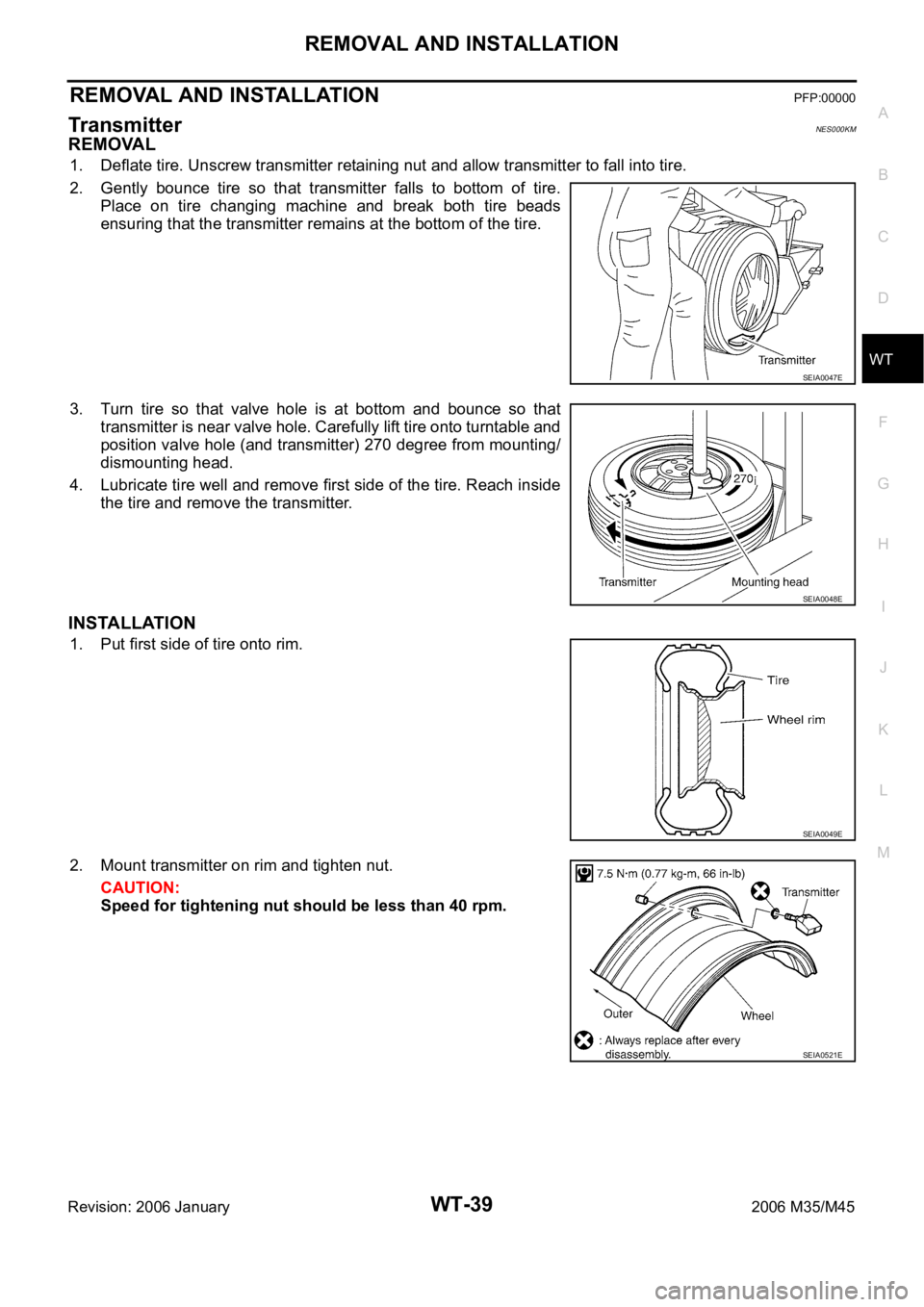
REMOVAL
1. Deflate tire. Unscrew transmitter retaining nut and allow transmitter to fall into tire.
2. Gently bounce tire so that transmitter falls to bottom of tire.
Place on tire changing machine and break both tire beads
ensuring that the transmitter remains at the bottom of the tire.
3. Turn tire so that valve hole is at bottom and bounce so that
transmitter is near valve hole. Carefully lift tire onto turntable and
position valve hole (and transmitter) 270 degree from mounting/
dismounting head.
4. Lubricate tire well and remove first side of the tire. Reach inside
the tire and remove the transmitter.
INSTALLATION
1. Put first side of tire onto rim.
2. Mount transmitter on rim and tighten nut.
CAUTION:
Speed for tightening nut should be less than 40 rpm.
SEIA0047E
SEIA0048E
SEIA0049E
SEIA0521E