2006 INFINITI M35 sensor
[x] Cancel search: sensorPage 5115 of 5621
SB-16
PRE-CRASH SEAT BELT
Revision: 2006 January2006 M35/M45
Preliminary CheckNHS00086
PRE-CRASH SEAT BELT OPERATION INSPECTION
WAR NING :
The following tests should be performed in a safe, open place that is free of traffic and obstacles.
The tests should be performed on a dry, paved road. Do not attempt the tests on wet or unpaved
road, open road, or highway. (This may cause an accident or personal injury.)
Driver and passenger assume it will not operate and prepare themselves accordingly.
1. Tighten driver and passenger seat belts.
2. Drive at approximately 25 km/h (16 MPH).
3. Notify passenger of a sudden stop. Driver and passenger prepare themselves for the possibility of
system not operating. Then, driver fully depresses the brake pedal to stop suddenly.
4. Make sure that the shoulder of the seat belt is pulled while braking.
Diagnoses Symptom ChartNHS00087
Check CAN Communication System Inspection [U1000]NHS00088
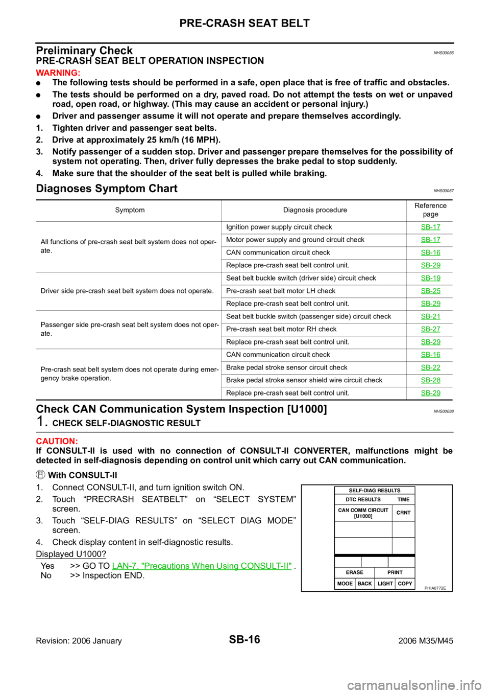
1. CHECK SELF-DIAGNOSTIC RESULT
CAUTION:
If CONSULT-II is used with no connection of CONSULT-II CONVERTER, malfunctions might be
detected in self-diagnosis depending on control unit which carry out CAN communication.
With CONSULT-II
1. Connect CONSULT-II, and turn ignition switch ON.
2. Touch “PRECRASH SEATBELT” on “SELECT SYSTEM”
screen.
3. Touch “SELF-DIAG RESULTS” on “SELECT DIAG MODE”
screen.
4. Check display content in self-diagnostic results.
Displayed U1000?
Yes >> GO TO LAN-7, "Precautions When Using CONSULT-II" .
No >> Inspection END.
Symptom Diagnosis procedureReference
page
All functions of pre-crash seat belt system does not oper-
ate.Ignition power supply circuit checkSB-17
Motor power supply and ground circuit checkSB-17
CAN communication circuit checkSB-16
Replace pre-crash seat belt control unit.SB-29
Driver side pre-crash seat belt system does not operate.Seat belt buckle switch (driver side) circuit checkSB-19Pre-crash seat belt motor LH checkSB-25
Replace pre-crash seat belt control unit.SB-29
Passenger side pre-crash seat belt system does not oper-
ate.Seat belt buckle switch (passenger side) circuit checkSB-21Pre-crash seat belt motor RH checkSB-27
Replace pre-crash seat belt control unit.SB-29
Pre-crash seat belt system does not operate during emer-
gency brake operation.CAN communication circuit checkSB-16Brake pedal stroke sensor circuit checkSB-22
Brake pedal stroke sensor shield wire circuit checkSB-28
Replace pre-crash seat belt control unit.SB-29
PHIA0772E
Page 5121 of 5621
SB-22
PRE-CRASH SEAT BELT
Revision: 2006 January2006 M35/M45
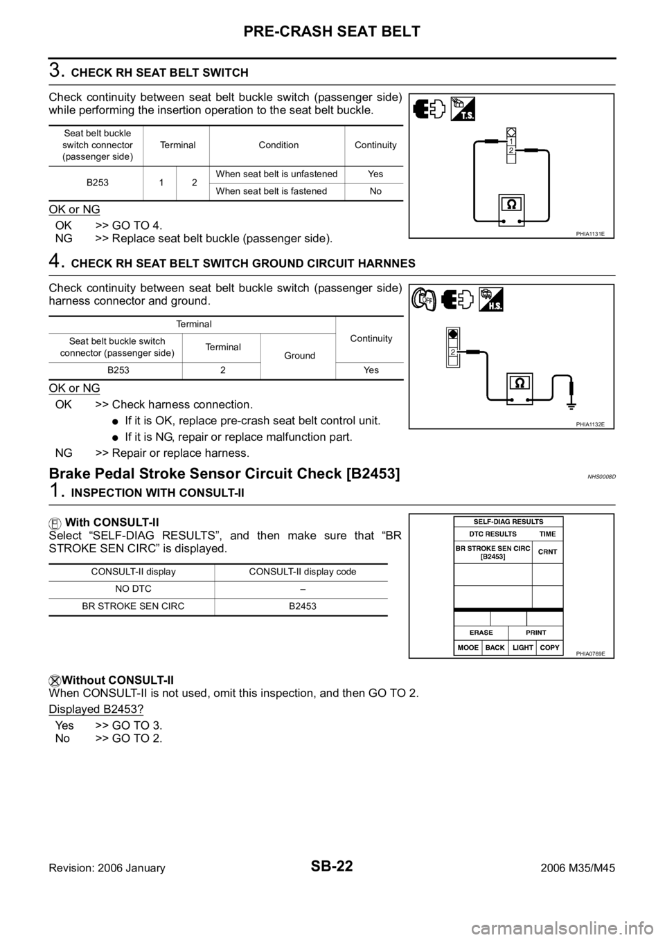
3. CHECK RH SEAT BELT SWITCH
Check continuity between seat belt buckle switch (passenger side)
while performing the insertion operation to the seat belt buckle.
OK or NG
OK >> GO TO 4.
NG >> Replace seat belt buckle (passenger side).
4. CHECK RH SEAT BELT SWITCH GROUND CIRCUIT HARNNES
Check continuity between seat belt buckle switch (passenger side)
harness connector and ground.
OK or NG
OK >> Check harness connection.
If it is OK, replace pre-crash seat belt control unit.
If it is NG, repair or replace malfunction part.
NG >> Repair or replace harness.
Brake Pedal Stroke Sensor Circuit Check [B2453]NHS0008D
1. INSPECTION WITH CONSULT-II
With CONSULT-II
Select “SELF-DIAG RESULTS”, and then make sure that “BR
STROKE SEN CIRC” is displayed.
Without CONSULT-II
When CONSULT-II is not used, omit this inspection, and then GO TO 2.
Displayed B2453?
Yes >> GO TO 3.
No >> GO TO 2.
Seat belt buckle
switch connector
(passenger side)Terminal Condition Continuity
B253 1 2When seat belt is unfastened Yes
When seat belt is fastened No
PHIA1131E
Te r m i n a l
Continuity
Seat belt buckle switch
connector (passenger side) Terminal
Ground
B253 2 Yes
PHIA1132E
CONSULT-II display CONSULT-II display code
NO DTC –
BR STROKE SEN CIRC B2453
PHIA0769E
Page 5122 of 5621
PRE-CRASH SEAT BELT
SB-23
C
D
E
F
G
I
J
K
L
MA
B
SB
Revision: 2006 January2006 M35/M45
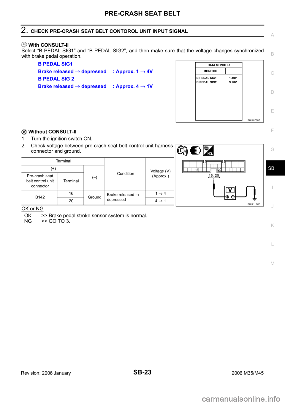
2. CHECK PRE-CRASH SEAT BELT CONTOROL UNIT INPUT SIGNAL
With CONSULT-II
Select “B PEDAL SIG1” and “B PEDAL SIG2”, and then make sure that the voltage changes synchronized
with brake pedal operation.
Without CONSULT-II
1. Turn the ignition switch ON.
2. Check voltage between pre-crash seat belt control unit harness
connector and ground.
OK or NG
OK >> Brake pedal stroke sensor system is normal.
NG >> GO TO 3.B PEDAL SIG1
Brake released
depressed : Approx. 1 4V
B PEDAL SIG 2
Brake released
depressed : Approx. 4 1V
PHIA0766E
Terminal
ConditionVoltage (V)
(Approx.) (+)
(–) Pre-crash seat
belt control unit
connectorTe r m i n a l
B14216
GroundBrake released
depressed1 4
20 4
1PHIA1134E
Page 5123 of 5621
SB-24
PRE-CRASH SEAT BELT
Revision: 2006 January2006 M35/M45
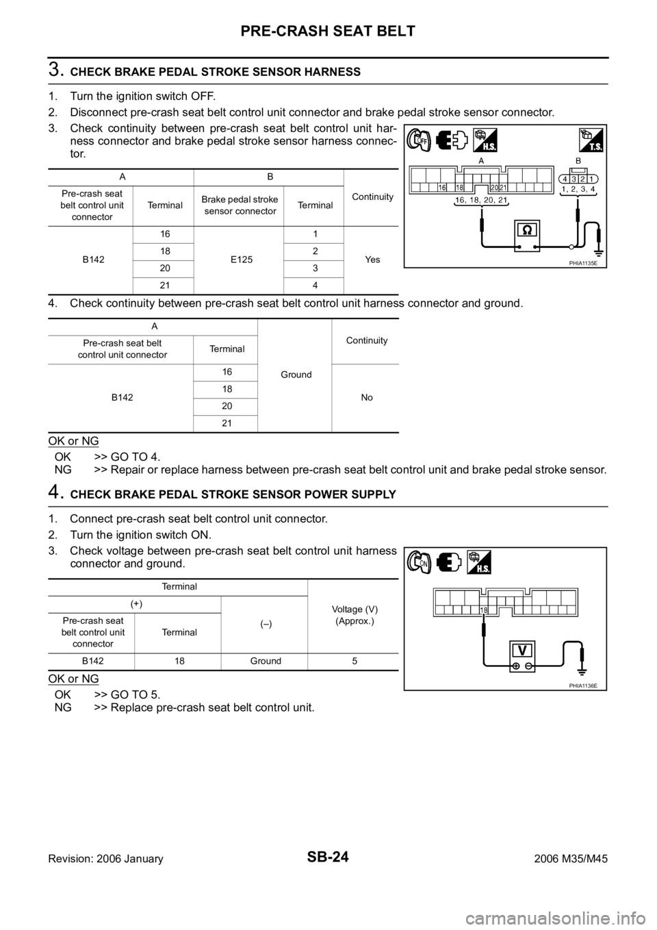
3. CHECK BRAKE PEDAL STROKE SENSOR HARNESS
1. Turn the ignition switch OFF.
2. Disconnect pre-crash seat belt control unit connector and brake pedal stroke sensor connector.
3. Check continuity between pre-crash seat belt control unit har-
ness connector and brake pedal stroke sensor harness connec-
tor.
4. Check continuity between pre-crash seat belt control unit harness connector and ground.
OK or NG
OK >> GO TO 4.
NG >> Repair or replace harness between pre-crash seat belt control unit and brake pedal stroke sensor.
4. CHECK BRAKE PEDAL STROKE SENSOR POWER SUPPLY
1. Connect pre-crash seat belt control unit connector.
2. Turn the ignition switch ON.
3. Check voltage between pre-crash seat belt control unit harness
connector and ground.
OK or NG
OK >> GO TO 5.
NG >> Replace pre-crash seat belt control unit.
AB
Continuity Pre-crash seat
belt control unit
connectorTe r m i n a lBrake pedal stroke
sensor connectorTerminal
B14216
E1251
Ye s 18 2
20 3
21 4
A
GroundContinuity
Pre-crash seat belt
control unit connectorTerminal
B14216
No 18
20
21
PHIA1135E
Terminal
Voltage (V)
(Approx.) (+)
(–) Pre-crash seat
belt control unit
connectorTerminal
B142 18 Ground 5
PHIA1136E
Page 5124 of 5621

PRE-CRASH SEAT BELT
SB-25
C
D
E
F
G
I
J
K
L
MA
B
SB
Revision: 2006 January2006 M35/M45
5. CHECK BRAKE PEDAL STROKE SENSOR
Check continuity between brake pedal stroke sensor while perform-
ing brake operation.
OK or NG
OK >> Check harness connection.
If it is OK, replace pre-crash seat belt control unit.
If it is NG, repair or replace malfunction part.
NG >> Replace brake pedal stroke sensor.
Pre-Crash Seat Belt Motor LH Circuit Check [B2452]NHS0008E
1. CHECK LH SEAT BELT MOTOR CIRCUIT
With CONSULT-II
Select “SELF-DIAG RESULTS” of CONSULT-II, and then make sure
that “SB MOTOR LH CIRC” is displayed.
Without CONSULT-II
When CONSULT-II is not used, omit this inspection, and then GO TO 2.
Displayed B2452?
Ye s > > G O T O 2 .
No >> Pre-crash seat belt motor LH circuit is OK.
Brake pedal stroke
sensor connectorTerminal ConditionResistance
(K)
(Approx.)
E125 21
Brake released
depressed1.0 0.2
30.2
1.0
PHIA1137E
CONSULT-II display CONSULT-II display code
NO DTC –
SB MOTOR LH CIRC B2452
PHIA0768E
Page 5127 of 5621
SB-28
PRE-CRASH SEAT BELT
Revision: 2006 January2006 M35/M45
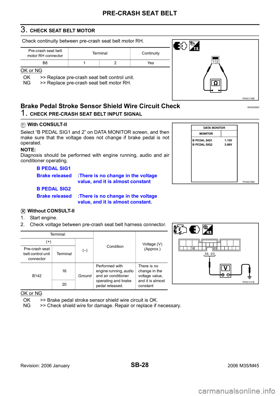
3. CHECK SEAT BELT MOTOR
Check continuity between pre-crash seat belt motor RH.
OK or NG
OK >> Replace pre-crash seat belt control unit.
NG >> Replace pre-crash seat belt motor RH.
Brake Pedal Stroke Sensor Shield Wire Circuit CheckNHS0008G
1. CHECK PRE-CRASH SEAT BELT INPUT SIGNAL
With CONSULT-II
Select “B PEDAL SIG1 and 2” on DATA MONITOR screen, and then
make sure that the voltage does not change if brake pedal is not
operated.
NOTE:
Diagnosis should be performed with engine running, audio and air
conditioner operating.
Without CONSULT-II
1. Start engine.
2. Check voltage between pre-crash seat belt harness connector.
OK or NG
OK >> Brake pedal stroke sensor shield wire circuit is OK.
NG >> Check shield wire for damage. Repair or replace if necessary.
Pre-crash seat belt
motor RH connectorTerminal Continuity
B8 1 2 Yes
PHIA1139E
B PEDAL SIG1
Brake released :There is no change in the voltage
value, and it is almost constant
B PEDAL SIG2
Brake released :There is no change in the voltage
value, and it is almost constant.
Terminal
ConditionVoltage (V)
(Approx.) (+)
(–) Pre-crash seat
belt control unit
connectorTerminal
B14216
GroundPerformed with
engine running, audio
and air conditioner
operating and brake
pedal released.There is no
change in the
voltage value,
and it is almost
constant 20
PHIA0766E
PHIA1141E
Page 5129 of 5621
SB-30
SEAT BELTS
Revision: 2006 January2006 M35/M45
SEAT BELTSPFP:86884
System DescriptionNHS0008I
SEAT BELT WARNING CHIME
With ignition switch turned ON and seat belt unfastened (seat belt switch ON), warning chime will sound
for approximately 6 seconds.
If warning chime does not sound, refer to DI-74, "Seat Belt Buckle Switch Signal Inspection" .
SEAT BELT WARNING LAMP
Fasten driver's seat belt.
The seat belt warning lamp should go out.
If the seat belt warning lamp does not go out, refer to DI-43, "Wiring Diagram — WARN —" .
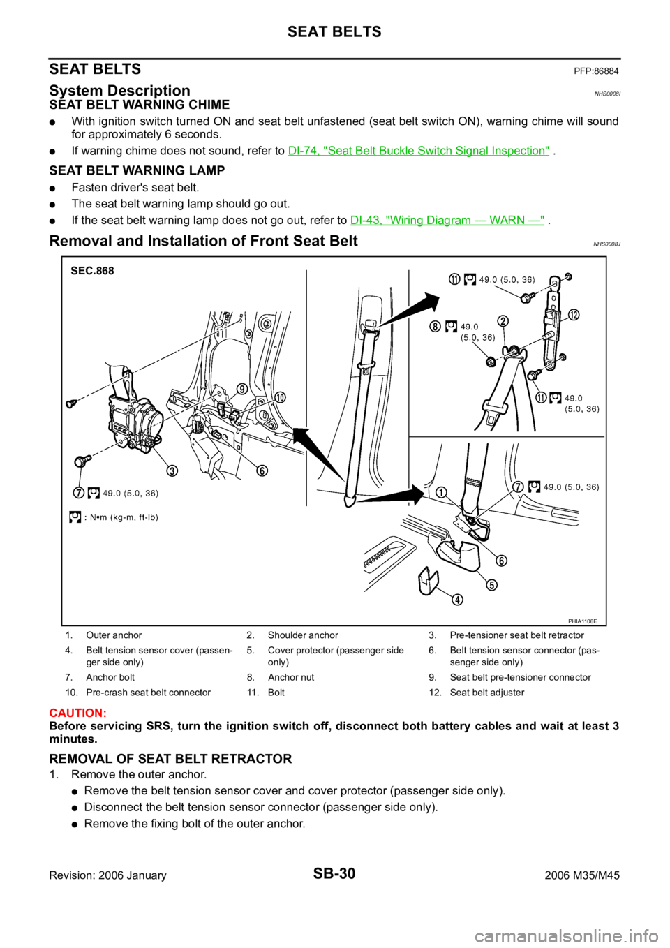
Removal and Installation of Front Seat Belt NHS0008J
CAUTION:
Before servicing SRS, turn the ignition switch off, disconnect both battery cables and wait at least 3
minutes.
REMOVAL OF SEAT BELT RETRACTOR
1. Remove the outer anchor.
Remove the belt tension sensor cover and cover protector (passenger side only).
Disconnect the belt tension sensor connector (passenger side only).
Remove the fixing bolt of the outer anchor.
1. Outer anchor 2. Shoulder anchor 3. Pre-tensioner seat belt retractor
4. Belt tension sensor cover (passen-
ger side only)5. Cover protector (passenger side
only)6. Belt tension sensor connector (pas-
senger side only)
7. Anchor bolt 8. Anchor nut 9. Seat belt pre-tensioner connector
10. Pre-crash seat belt connector 11. Bolt 12. Seat belt adjuster
PHIA1106E
Page 5139 of 5621

SC-2
PRECAUTIONS
Revision: 2006 January2006 M35/M45
PRECAUTIONS PFP:00011
Precautions for Supplemental Restraint System (SRS) “AIR BAG” and “SEAT
BELT PRE-TENSIONER”
NKS003NB
The Supplemental Restraint System such as “AIR BAG” and “SEAT BELT PRE-TENSIONER”, used along
with a front seat belt, helps to reduce the risk or severity of injury to the driver and front passenger for certain
types of collision. This system includes seat belt switch inputs and dual stage front air bag modules. The SRS
system uses the seat belt switches to determine the front air bag deployment, and may only deploy one front
air bag, depending on the severity of a collision and whether the front occupants are belted or unbelted.
Information necessary to service the system safely is included in the SRS and SB section of this Service Man-
ual.
WAR NING :
To avoid rendering the SRS inoperative, which could increase the risk of personal injury or death
in the event of a collision which would result in air bag inflation, all maintenance must be per-
formed by an authorized NISSAN/INFINITI dealer.
Improper maintenance, including incorrect removal and installation of the SRS, can lead to per-
sonal injury caused by unintentional activation of the system. For removal of Spiral Cable and Air
Bag Module, see the SRS section.
Do not use electrical test equipment on any circuit related to the SRS unless instructed to in this
Service Manual. SRS wiring harnesses can be identified by yellow and/or orange harnesses or
harness connectors.
Precautions for Power Generation Voltage Variable Control SystemNKS003NC
CAUTION:
For this model, the battery current sensor that is installed to the battery cable at the negative terminal
measures the charging/discharging current of the battery, and performs various controls. If the electri-
cal component or the ground wire is connected directly to the battery terminal, the current other than
that being measured with the battery current sensor is charging to or discharging from the battery.
This condition causes the malfunction of the control, and then the battery discharge may occur. Do
not connect the electrical component or the ground wire directly to the battery terminal.