Page 4972 of 5621

POWER STEERING GEAR
PS-19
C
D
E
F
H
I
J
K
L
MA
B
PS
Revision: 2006 January2006 M35/M45
8. Remove steering hydraulic piping bracket from front suspension member. Refer to PS-38, "HYDRAULIC
LINE" .
9. Remove EPS solenoid valve harness connector. Refer to PS-20, "
COMPONENTS" .
10. Remove rack stay (2WD) or front cross bar (AWD). Refer to FSU-8, "
Components" , FSU-25, "Compo-
nents" .
11. Remove mounting bolts and nuts of steering gear assembly, and then remove steering gear assembly
from vehicle.
INSTALLATION
Installation is the reverse order of removal. For tightening torque, refer to PS-18, "COMPONENTS" .
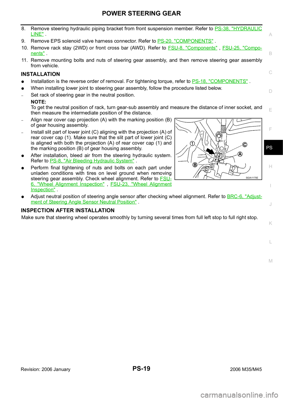
When installing lower joint to steering gear assembly, follow the procedure listed below.
–Set rack of steering gear in the neutral position.
NOTE:
To get the neutral position of rack, turn gear-sub assembly and measure the distance of inner socket, and
then measure the intermediate position of the distance.
–Align rear cover cap projection (A) with the marking position (B)
of gear housing assembly.
–Install slit part of lower joint (C) aligning with the projection (A) of
rear cover cap (1). Make sure that the slit part of lower joint (C)
is aligned with both the projection (A) of rear cover cap (1) and
the marking position (B) of gear housing assembly.
After installation, bleed air from the steering hydraulic system.
Refer to PS-8, "
Air Bleeding Hydraulic System" .
Perform final tightening of nuts and bolts on each part under
unladen conditions with tires on level ground when removing
steering gear assembly. Check wheel alignment. Refer to FSU-
6, "Wheel Alignment Inspection" , FSU-23, "Wheel Alignment
Inspection" .
Adjust neutral position of steering angle sensor after checking wheel alignment. Refer to BRC-6, "Adjust-
ment of Steering Angle Sensor Neutral Position" .
INSPECTION AFTER INSTALLATION
Make sure that steering wheel operates smoothly by turning several times from full left stop to full right stop.
SGIA1175E
Page 4991 of 5621
PS-38
HYDRAULIC LINE
Revision: 2006 January2006 M35/M45
HYDRAULIC LINEPFP:49721
ComponentsNGS000DI
CAUTION:
Securely insert harness connector to pressure sensor.
VQ35DE 2WD MODELS
SGIA1390E
Page 4992 of 5621
HYDRAULIC LINE
PS-39
C
D
E
F
H
I
J
K
L
MA
B
PS
Revision: 2006 January2006 M35/M45
1. Reservoir tank 2. Reservoir tank bracket 3. Suction hose
4. High pressure hose 5. Oil pump assembly 6. Steering gear assembly
7. Low pressure piping 8. High pressure piping 9. O-ring
10. Eye-bolt 11. Copper washer 12. Eye-joint (assembled to high-pres-
sure side hose)
13. Pressure sensor 14. Oil pump bracket
Refer to GI-11, "
Components" , and the followings for the symbols in the figure.
: Apply power steering fluid.
Page 4993 of 5621
PS-40
HYDRAULIC LINE
Revision: 2006 January2006 M35/M45
VQ35DE AWD MODELS
1. Reservoir tank 2. Reservoir tank bracket 3. Suction hose
4. High-pressure hose 5. Oil pump assembly 6. Steering gear assembly
7. Low pressure piping 8. High pressure piping 9. O-ring
10. Eye-bolt 11. Copper washer 12. Eye-joint (assembled to high-pres-
sure side hose)
13. Pressure sensor 14. Oil pump bracket
SGIA1191E
Page 4995 of 5621
PS-42
HYDRAULIC LINE
Revision: 2006 January2006 M35/M45
VK45DE MODELS
1. Reservoir tank 2. Reservoir tank bracket 3. Suction hose
4. High-pressure hose 5. Oil pump assembly 6. Steering gear assembly
7. Low pressure piping 8. High pressure piping 9. O-ring
10. Eye-bolt 11. Copper washer 12. Eye-joint (assembled to high-pres-
sure side hose)
13. Pressure sensor 14. Oil pump bracket
SGIA1391E
Page 5006 of 5621

WHEEL HUB
RAX-7
C
E
F
G
H
I
J
K
L
MA
B
RAX
Revision: 2006 January2006 M35/M45
INSTALLATION
Wheel Hub and Bearing Assembly
Installation is the reverse order of removal. For tightening torque refer to RAX-5, "COMPONENT" .
CAUTION:
Do not reuse non-reusable parts.
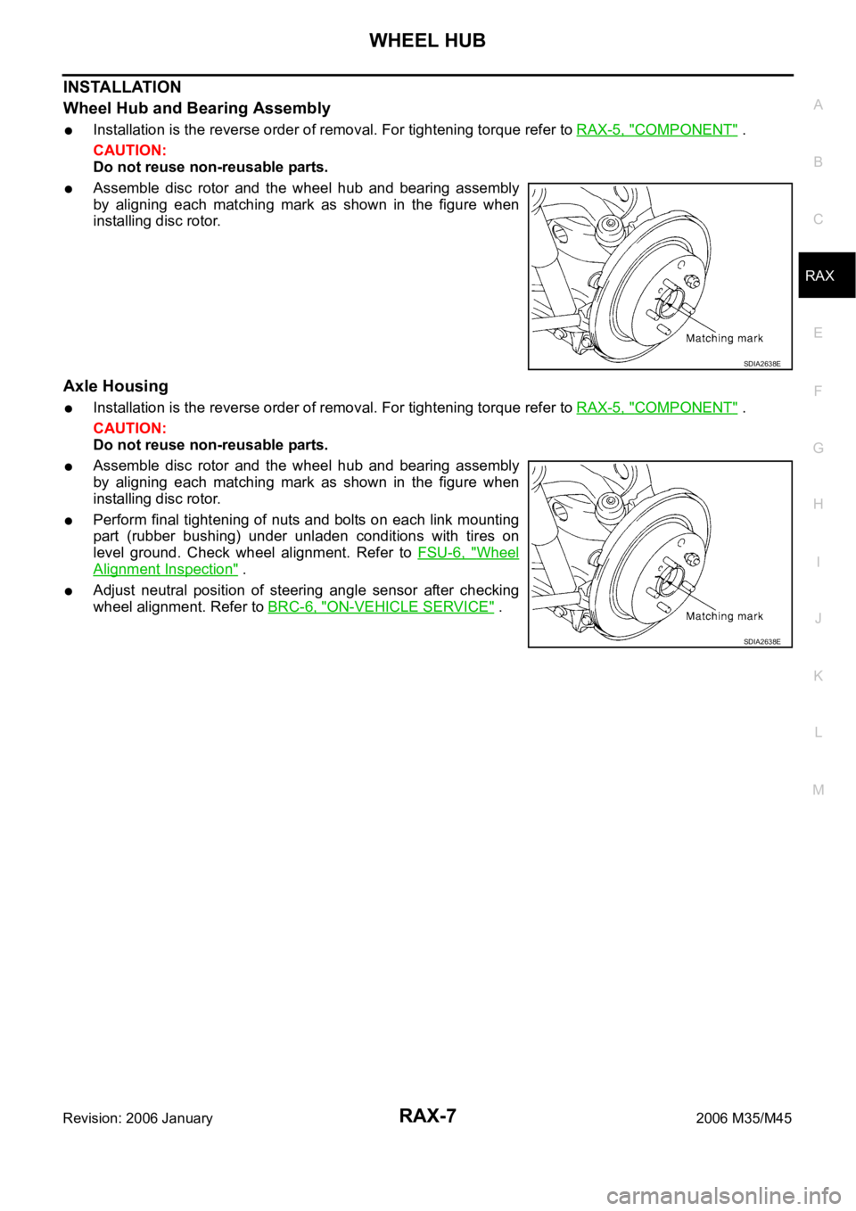
Assemble disc rotor and the wheel hub and bearing assembly
by aligning each matching mark as shown in the figure when
installing disc rotor.
Axle Housing
Installation is the reverse order of removal. For tightening torque refer to RAX-5, "COMPONENT" .
CAUTION:
Do not reuse non-reusable parts.
Assemble disc rotor and the wheel hub and bearing assembly
by aligning each matching mark as shown in the figure when
installing disc rotor.
Perform final tightening of nuts and bolts on each link mounting
part (rubber bushing) under unladen conditions with tires on
level ground. Check wheel alignment. Refer to FSU-6, "
Wheel
Alignment Inspection" .
Adjust neutral position of steering angle sensor after checking
wheel alignment. Refer to BRC-6, "
ON-VEHICLE SERVICE" .
SDIA2638E
SDIA2638E
Page 5053 of 5621

RFD-10
FRONT OIL SEAL
Revision: 2006 January2006 M35/M45
FRONT OIL SEALPFP:38189
Removal and InstallationNDS000F5
CAUTION:
Verify identification stamp of replacement frequency put in the lower part of gear carrier to determine
replacement for collapsible spacer when replacing front oil seal. Refer to RFD-10, "
IDENTIFICATION
STAMP OF REPLACEMENT FREQUENCY OF FRONT OIL SEAL" . If necessary collapsible spacer
replacement, remove final drive assembly and disassemble it to replace front oil seal and collapsible
spacer. Refer to RFD-16, "
Removal and Installation" and RFD-18, "Disassembly and Assembly" .
NOTE:
The reuse of collapsible spacer is prohibited in principle. However, it is reusable on a one-time basis
only in cases when replacing front oil seal.
IDENTIFICATION STAMP OF REPLACEMENT FREQUENCY OF FRONT OIL SEAL
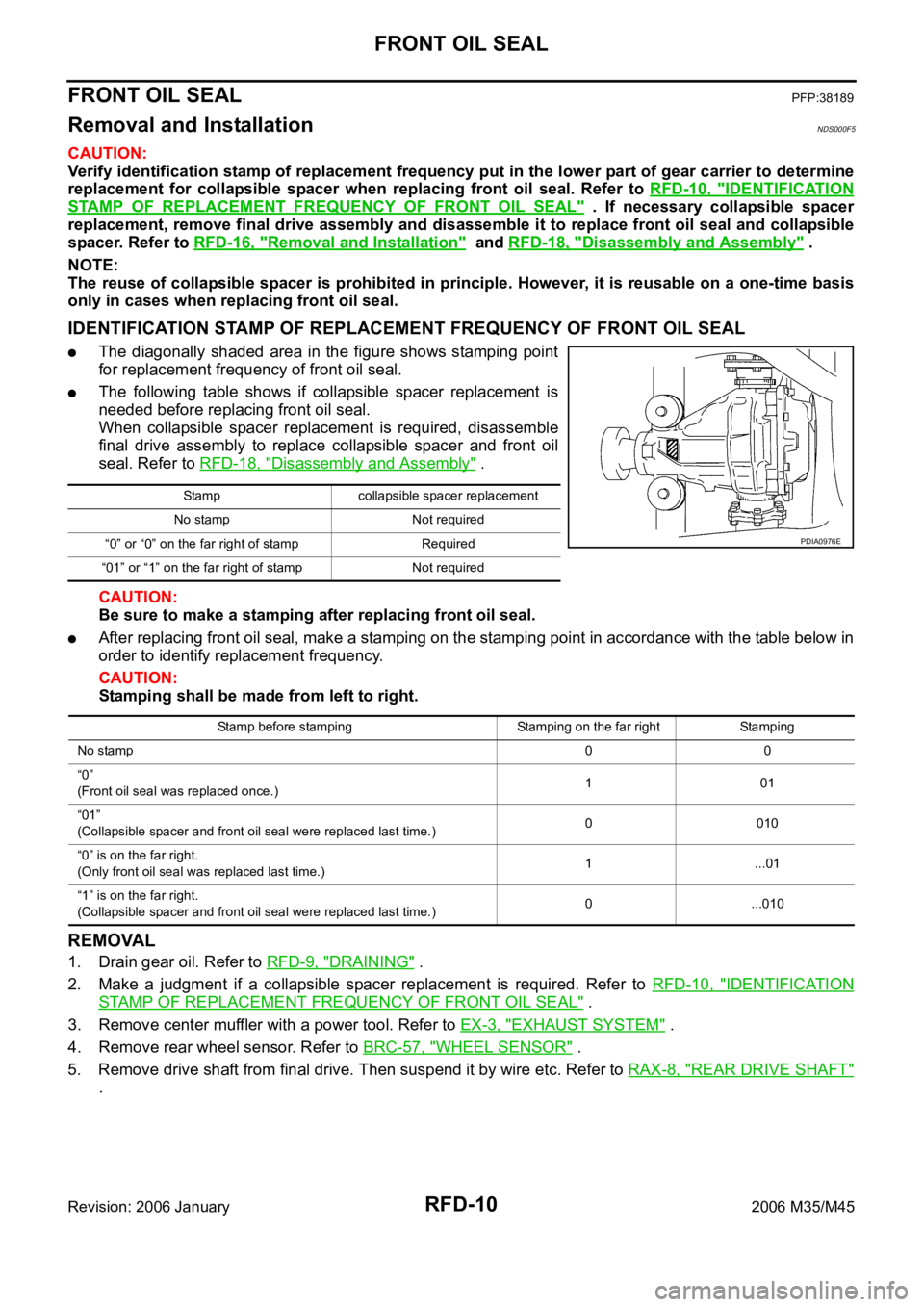
The diagonally shaded area in the figure shows stamping point
for replacement frequency of front oil seal.
The following table shows if collapsible spacer replacement is
needed before replacing front oil seal.
When collapsible spacer replacement is required, disassemble
final drive assembly to replace collapsible spacer and front oil
seal. Refer to RFD-18, "
Disassembly and Assembly" .
CAUTION:
Be sure to make a stamping after replacing front oil seal.
After replacing front oil seal, make a stamping on the stamping point in accordance with the table below in
order to identify replacement frequency.
CAUTION:
Stamping shall be made from left to right.
REMOVAL
1. Drain gear oil. Refer to RFD-9, "DRAINING" .
2. Make a judgment if a collapsible spacer replacement is required. Refer to RFD-10, "
IDENTIFICATION
STAMP OF REPLACEMENT FREQUENCY OF FRONT OIL SEAL" .
3. Remove center muffler with a power tool. Refer to EX-3, "
EXHAUST SYSTEM" .
4. Remove rear wheel sensor. Refer to BRC-57, "
WHEEL SENSOR" .
5. Remove drive shaft from final drive. Then suspend it by wire etc. Refer to RAX-8, "
REAR DRIVE SHAFT"
.
Stamp collapsible spacer replacement
No stamp Not required
“0” or “0” on the far right of stamp Required
“01” or “1” on the far right of stamp Not required
PDIA0976E
Stamp before stamping Stamping on the far right Stamping
No stamp00
“0”
(Front oil seal was replaced once.)101
“01”
(Collapsible spacer and front oil seal were replaced last time.)0 010
“0” is on the far right.
(Only front oil seal was replaced last time.)1...01
“1” is on the far right.
(Collapsible spacer and front oil seal were replaced last time.)0 ...010
Page 5056 of 5621

FRONT OIL SEAL
RFD-13
C
E
F
G
H
I
J
K
L
MA
B
RFD
Revision: 2006 January2006 M35/M45
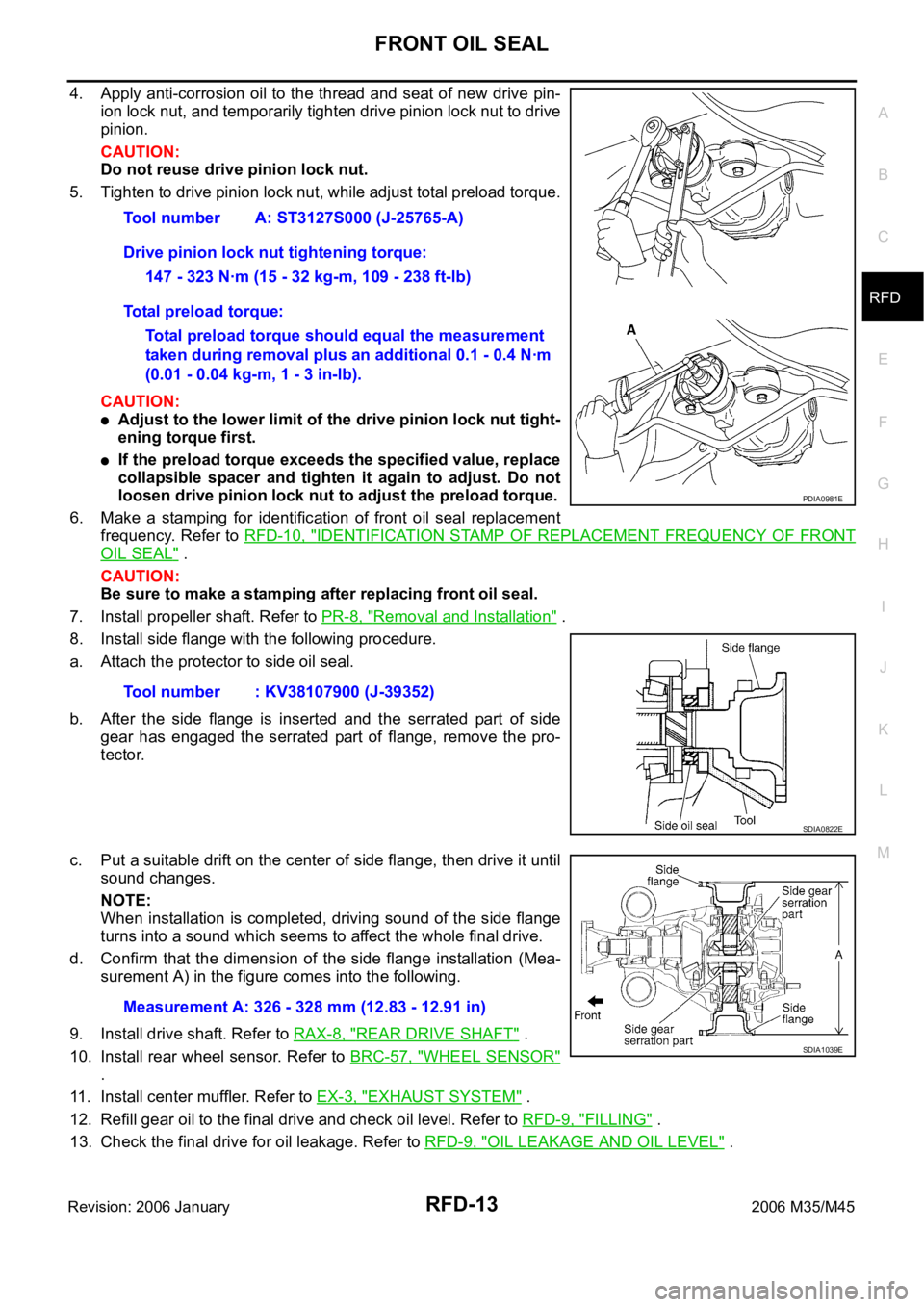
4. Apply anti-corrosion oil to the thread and seat of new drive pin-
ion lock nut, and temporarily tighten drive pinion lock nut to drive
pinion.
CAUTION:
Do not reuse drive pinion lock nut.
5. Tighten to drive pinion lock nut, while adjust total preload torque.
CAUTION:
Adjust to the lower limit of the drive pinion lock nut tight-
ening torque first.
If the preload torque exceeds the specified value, replace
collapsible spacer and tighten it again to adjust. Do not
loosen drive pinion lock nut to adjust the preload torque.
6. Make a stamping for identification of front oil seal replacement
frequency. Refer to RFD-10, "
IDENTIFICATION STAMP OF REPLACEMENT FREQUENCY OF FRONT
OIL SEAL" .
CAUTION:
Be sure to make a stamping after replacing front oil seal.
7. Install propeller shaft. Refer to PR-8, "
Removal and Installation" .
8. Install side flange with the following procedure.
a. Attach the protector to side oil seal.
b. After the side flange is inserted and the serrated part of side
gear has engaged the serrated part of flange, remove the pro-
tector.
c. Put a suitable drift on the center of side flange, then drive it until
sound changes.
NOTE:
When installation is completed, driving sound of the side flange
turns into a sound which seems to affect the whole final drive.
d. Confirm that the dimension of the side flange installation (Mea-
surement A) in the figure comes into the following.
9. Install drive shaft. Refer to RAX-8, "
REAR DRIVE SHAFT" .
10. Install rear wheel sensor. Refer to BRC-57, "
WHEEL SENSOR"
.
11. Install center muffler. Refer to EX-3, "
EXHAUST SYSTEM" .
12. Refill gear oil to the final drive and check oil level. Refer to RFD-9, "
FILLING" .
13. Check the final drive for oil leakage. Refer to RFD-9, "
OIL LEAKAGE AND OIL LEVEL" . Tool number A: ST3127S000 (J-25765-A)
Drive pinion lock nut tightening torque:
147 - 323 Nꞏm (15 - 32 kg-m, 109 - 238 ft-lb)
Total preload torque:
Total preload torque should equal the measurement
taken during removal plus an additional 0.1 - 0.4 Nꞏm
(0.01 - 0.04 kg-m, 1 - 3 in-lb).
Tool number : KV38107900 (J-39352)
PDIA0981E
SDIA0822E
Measurement A: 326 - 328 mm (12.83 - 12.91 in)
SDIA1039E