2006 INFINITI M35 sensor
[x] Cancel search: sensorPage 5161 of 5621
SC-24
CHARGING SYSTEM
Revision: 2006 January2006 M35/M45
POWER GENERATION VOLTAGE VARIABLE CONTROL SYSTEM
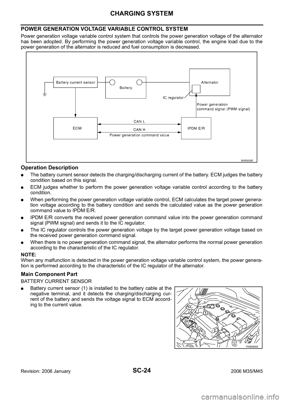
Power generation voltage variable control system that controls the power generation voltage of the alternator
has been adopted. By performing the power generation voltage variable control, the engine load due to the
power generation of the alternator is reduced and fuel consumption is decreased.
Operation Description
The battery current sensor detects the charging/discharging current of the battery. ECM judges the battery
condition based on this signal.
ECM judges whether to perform the power generation voltage variable control according to the battery
condition.
When performing the power generation voltage variable control, ECM calculates the target power genera-
tion voltage according to the battery condition and sends the calculated value as the power generation
command value to IPDM E/R.
IPDM E/R converts the received power generation command value into the power generation command
signal (PWM signal) and sends it to the IC regulator.
The IC regulator controls the power generation voltage by the target power generation voltage based on
the received power generation command signal.
When there is no power generation command signal, the alternator performs the normal power generation
according to the characteristic of the IC regulator.
NOTE:
When any malfunction is detected in the power generation voltage variable control system, the power genera-
tion is performed according to the characteristic of the IC regulator of the alternator.
Main Component Part
BATTERY CURRENT SENSOR
Battery current sensor (1) is installed to the battery cable at the
negative terminal, and it detects the charging/discharging cur-
rent of the battery and sends the voltage signal to ECM accord-
ing to the current value.
SKIB5009E
PKIB8806E
Page 5165 of 5621
SC-28
CHARGING SYSTEM
Revision: 2006 January2006 M35/M45
Trouble Diagnoses with Battery/Starting/Charging System Tester (Charging)NKS003NP
NOTE:
To ensure a complete and thorough diagnosis, the battery, starter and alternator test segments must be done
as a set from start to finish.
Before starting, perform the preliminary inspection. Refer to SC-32, "
PRELIMINARY INSPECTION" .
1. Stop the operation of the power generation voltage variable control in either of the following procedures.
After selecting “ENGINE” of “SELECT SYSTEM” using CONSULT-II, set the DUTY value of “ALTERNA-
TOR DUTY” to 0% by selecting “ALTERNATOR DUTY” of “ACTIVE TEST”. Continue “ACTIVE TEST”
until the end of inspection. (When the DUTY value is 0 or 100%, the normal power generation is per-
formed according to the characteristic of the IC regulator of the alternator.)
Turn the ignition switch OFF, and disconnect the battery current sensor connector. [However, DTC
(P1550 - P1554) of the engine might remain. After finishing the inspection, connect the battery current
sensor connector and erase the self-diagnostic results history of the engine using CONSULT-II.]
2. Turn off all loads on the vehicle electrical system.
3. Perform battery and starting system test with Battery/Starting/
Charging system tester.
4. Press “ENTER” to begin the charging system test.
5. Start engine.
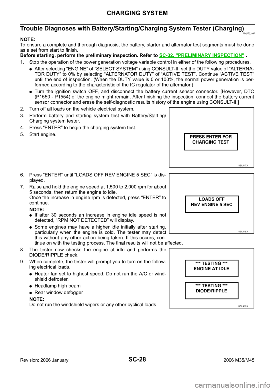
6. Press “ENTER” until “LOADS OFF REV ENGINE 5 SEC” is dis-
played.
7. Raise and hold the engine speed at 1,500 to 2,000 rpm for about
5 seconds, then return the engine to idle.
Once the increase in engine rpm is detected, press “ENTER” to
continue.
NOTE:
If after 30 seconds an increase in engine idle speed is not
detected, “RPM NOT DETECTED” will display.
Some engines may have a higher idle initially after starting,
particularly when the engine is cold. The tester may detect
this without any other action being taken. If this occurs, con-
tinue on with the testing process. The final results will not be affected.
8. The tester now checks the engine at idle and performs the
DIODE/RIPPLE check.
9. When complete, the tester will prompt you to turn on the follow-
ing electrical loads.
Heater fan set to highest speed. Do not run the A/C or wind-
shield defroster.
Headlamp high beam
Rear window defogger
NOTE:
Do not run the windshield wipers or any other cyclical loads.
SEL417X
SEL418X
SEL419X
Page 5172 of 5621
CHARGING SYSTEM
SC-35
C
D
E
F
G
H
I
J
L
MA
B
SC
Revision: 2006 January2006 M35/M45
Power Generation Voltage Variable Control System Operation InspectionNKS003NQ
CAUTION:
For this model, the battery current sensor that is installed to the battery cable at the negative ter-
minal measures the charging/discharging current of the battery, and performs various controls. If
the electrical component or the ground wire is connected directly to the battery terminal, the cur-
rent other than that being measured with the battery current sensor is charging to or discharging
from the battery. This condition causes the malfunction of the control, and then the battery dis-
charge may occur. Never connect the electrical component or the ground wire directly to the bat-
tery terminal.
When performing this inspection, always use the charged battery that completed the battery
inspection. (When the charging rate of the battery is low, the response speed of the voltage
change will become slow. This is a cause of an incorrect inspection.)
INSPECTION PROCEDURE
1. CHECK ECM (CONSULT-II)
Perform ECM self-diagnosis with CONSULT-II. Refer to EC-133, "
CONSULT-II Function (ENGINE)"
(VQ35DE) or EC-846, "CONSULT-II Function (ENGINE)" (VK45DE).
Self
-diagnostic results content
No malfunction detected>> GO TO 2.
Malfunction detected>> Check applicable parts, and repair or replace corresponding parts.
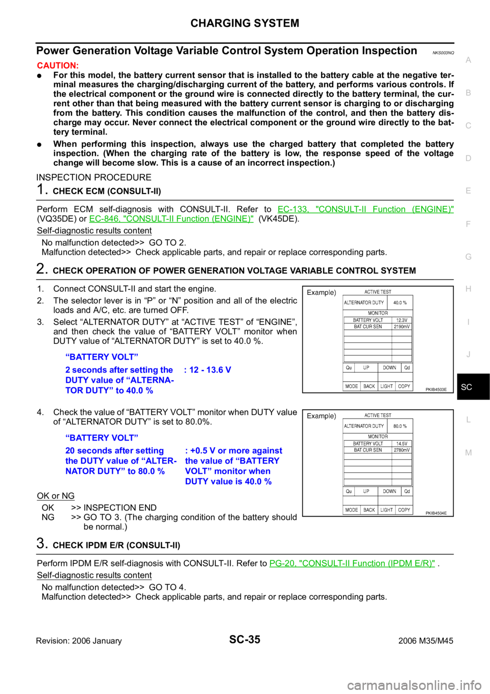
2. CHECK OPERATION OF POWER GENERATION VOLTAGE VARIABLE CONTROL SYSTEM
1. Connect CONSULT-II and start the engine.
2. The selector lever is in “P” or “N” position and all of the electric
loads and A/C, etc. are turned OFF.
3. Select “ALTERNATOR DUTY” at “ACTIVE TEST” of “ENGINE”,
and then check the value of “BATTERY VOLT” monitor when
DUTY value of “ALTERNATOR DUTY” is set to 40.0 %.
4. Check the value of “BATTERY VOLT” monitor when DUTY value
of “ALTERNATOR DUTY” is set to 80.0%.
OK or NG
OK >> INSPECTION END
NG >> GO TO 3. (The charging condition of the battery should
be normal.)
3. CHECK IPDM E/R (CONSULT-II)
Perform IPDM E/R self-diagnosis with CONSULT-II. Refer to PG-20, "
CONSULT-II Function (IPDM E/R)" .
Self
-diagnostic results content
No malfunction detected>> GO TO 4.
Malfunction detected>> Check applicable parts, and repair or replace corresponding parts. “BATTERY VOLT”
2 seconds after setting the
DUTY value of “ALTERNA-
TOR DUTY” to 40.0 %: 12 - 13.6 V
PKIB4503E
“BATTERY VOLT”
20 seconds after setting
the DUTY value of “ALTER-
NATOR DUTY” to 80.0 %: +0.5 V or more against
the value of “BATTERY
VOLT” monitor when
DUTY value is 40.0 %
PKIB4504E
Page 5182 of 5621
SE-1
SEAT
I BODY
CONTENTS
C
D
E
F
G
H
J
K
L
M
SECTION SE
A
B
SE
Revision: 2006 January2006 M35/M45
SEAT
PRECAUTIONS .......................................................... 3
Precautions for Supplemental Restraint System
(SRS) “AIR BAG” and “SEAT BELT PRE-TEN-
SIONER” .................................................................. 3
Service Notice .......................................................... 3
Precautions for Work ...........................................
..... 3
PREPARATION ........................................................... 4
Special Service Tools ............................................... 4
Commercial Service Tools ........................................ 4
SQUEAK AND RATTLE TROUBLE DIAGNOSES ..... 5
Work Flow ................................................................ 5
CUSTOMER INTERVIEW ..................................... 5
DUPLICATE THE NOISE AND TEST DRIVE ....... 6
CHECK RELATED SERVICE BULLETINS ........... 6
LOCATE THE NOISE AND IDENTIFY THE
ROOT CAUSE ...................................................... 6
REPAIR THE CAUSE ........................................... 6
CONFIRM THE REPAIR ....................................... 7
Generic Squeak and Rattle Troubleshooting ........... 7
INSTRUMENT PANEL .......................................... 7
CENTER CONSOLE ............................................. 7
DOORS ................................................................. 7
TRUNK .................................................................. 8
SUNROOF/HEADLINING ..................................... 8
SEATS ................................................................... 8
UNDERHOOD ....................................................... 8
Diagnostic Worksheet .............................................. 9
AUTOMATIC DRIVE POSITIONER ...........................11
Component Parts And Harness Connector Location
.... 11
System Description ................................................ 12
MANUAL OPERATION ....................................... 12
MEMORY OPERATION ...................................... 12
EXITING OPERATION ........................................ 14
ENTRY OPERATION .......................................... 14
INTELLIGENT KEY INTERLOCK OPERATION ... 15
FAIL-SAFE MODE .............................................. 15
INITIALIZATION PROCEDURE .......................... 16
SETTING CHANGE FUNCTION ......................... 16
CAN Communication System Description .............. 16CAN Communication Unit ....................................... 16
Schematic ............................................................... 17
Wiring Diagram—AUT/DP— .................................. 19
Terminals and Reference Values for BCM .............. 30
Terminals and Reference Value for Intelligent Key
Unit ......................................................................... 30
Terminals and Reference Values for Driver Seat
Control Unit ............................................................. 31
Terminals and Reference Values for Automatic
Drive Positioner Control Unit .................................. 33
CONSULT-II Function (AUTO DRIVE POS.) .......... 35
CONSULT-II INSPECTION PROCEDURE .......... 35
SELF-DIAGNOSIS RESULTS ............................. 36
DATA MONITOR ................................................. 37
ACTIVE TEST ..................................................... 38
WORK SUPPORT ............................................... 38
Work Flow ............................................................... 39
Symptom Chart ....................................................... 39
CAN Communication Inspection Using CONSULT-
II (Self-Diagnosis) ................................................... 41
BCM Power Supply and Ground Circuit Check ...... 41
Driver Seat Control Unit Power Supply and Ground
Circuit Check .......................................................... 42
Automatic Drive Positioner Power Supply and
Ground Circuit Check ............................................. 43
Sliding Motor Circuit Check .................................... 44
Reclining Motor LH Circuit Check ........................... 45
Front Lifting Motor Circuit Check ............................ 46
Rear Lifting Motor Circuit Check ............................. 48
Telescopic Motor Circuit Check .............................. 49
Tilt Motor Circuit Check .......................................
... 50
Sliding Sensor Circuit Check .................................. 52
Reclining Sensor Circuit Check .............................. 54
Front Lifting Sensor Circuit Check .......................... 56
Rear Lifting Sensor Circuit Check .......................... 58
Telescopic Sensor Circuit Check ............................ 60
Tilt Sensor Circuit Check ........................................ 62
Door Mirror Sensor LH Circuit Check ..................... 63
Door Mirror Sensor RH Circuit Check .................... 66
Sliding Switch Circuit Check ................................... 68
Page 5183 of 5621

SE-2Revision: 2006 January2006 M35/M45 Reclining Switch Circuit Check ............................... 70
Lifting Switch (Front) Circuit Check ........................ 72
Lifting Switch (Rear) Circuit Check ......................... 74
Power Seat Switch Ground Circuit Check .............. 75
Telescopic Switch Circuit Check ............................. 76
Tilt Switch Circuit Check ......................................
... 78
Seat Memory and Set Switch Circuit Check ........... 80
Seat Memory Indicator Lamp Circuit Check ........... 81
Door Mirror Sensor Power Supply and Ground Cir-
cuit Check ............................................................... 83
A/T Device (Detention Switch) Circuit Check ......... 85
Front Door Switch (Driver Side) Circuit Check ....... 86
UART Communication Line Circuit Check .............. 87
Lumber Support Circuit Check ............................... 89
POWER SEAT(PASSENGER SIDE) ......................... 91
Component Parts and Harness Connector Location ... 91
Wiring Diagram—SEAT—/Passenger Side ............ 92
Terminals and Reference Values for BCM .............. 94
POWER SEAT(REAR) .............................................. 95
Component Parts and Harness Connector Location ... 95
System Description ................................................. 95
REAR POWER SEAT LH AND RH OPERATION ... 95
REAR SEAT RETREAT FUNCTION ................... 96
Schematic ............................................................... 97
Wiring Diagram—R/SEAT— ................................... 98
Terminals and Reference Values for Rear Seat Con-
trol Unit .................................................................102
Work Flow .............................................................103
Trouble Diagnoses Symptom Chart ......................103
Rear Power Seat Power Supply Circuit Inspection .103
Rear Seat Control Unit Power Supply and Ground
Circuit Inspection ..................................................104
Rear Seat Sliding Motor Circuit Inspection ...........105
Rear Power Seat Switch Circuit Inspection ..........106
Automatic Return Cancel Switch Circuit Inspection .108
Automatic Return Cancel Switch Inspection .........109
Rear Door Switch Circuit Inspection .....................110
Rear Seat Sliding Sensor Circuit Inspection ..........111
CLIMATE CONTROLLED SEAT .............................113
Component Parts and Harness Connector Location .113
System Description ...............................................113
Schematic .............................................................117
Wiring Diagram—C/SEAT— .................................118
Terminal and Reference Value for Climate Con-
trolled Seat Control Unit ......................................
.123
Work Flow .............................................................124
Preliminary Check ................................................124
Trouble Diagnoses Symptom Chart .....................
.125
Climate Controlled Seat Control Unit Power Supply
Circuit Check ........................................................126
Climate Controlled Seat Control Unit Power Supply
and Ground Circuit Inspection ..............................127
Climate Controlled Seat Switch Power Supply Cir-cuit Inspection .......................................................130
Climate Controlled Seat Switch Circuit Inspection .131
Climate Controlled Seat Switch Indicator Circuit
Inspection ..............................................................133
Seat Cushion Thermal Electric Device Circuit
Inspection ..............................................................135
Seatback Thermal Electric Device Circuit Inspec-
tion ........................................................................136
Seat Cushion Thermal Electric Device Sensor Cir-
cuit Inspection .......................................................137
Seatback Thermal Electric Device Sensor Circuit
Inspection ..............................................................139
Climate Controlled Seat Blower Motor Circuit
Inspection ..............................................................140
Climate Controlled Seat Control Unit Inspection ...142
HEATED SEAT ........................................................143
Component Parts and Harness Connector Location .143
System Description ...............................................143
Schematic .............................................................145
Wiring Diagram —HSEAT— .................................146
Terminals and Reference Values for Rear Seat Con-
trol Unit ..................................................................151
Work Flow .............................................................151
Trouble Diagnoses Symptom Chart ......................151
Rear Heated Seat Power Supply and Ground Circuit
Inspection ..............................................................152
Rear Seat Control Unit Power Supply and Ground
Circuit Inspection ..................................................153
Rear Heated Seat Switch Circuit Inspection .........155
Rear Heated Seat Indicator Power Supply Circuit
Inspection ..............................................................157
Rear Heated Seat Indicator Circuit Inspection ......158
Rear Heated Seat Circuit Inspection .....................160
Rear Seatback Heater Circuit Inspection ..............161
FRONT SEAT ..........................................................163
Driver's Seat Components ....................................163
Passenger's Seat Components .............................165
Removal and Installation .......................................167
REMOVAL ..........................................................167
INSTALLATION ..................................................167
Disassembly and Assembly ..................................168
SEATBACK ........................................................168
SEAT CUSHION ................................................169
CLIMATE CONTROLLED SEAT ........................171
REAR SEAT .............................................................172
Bench Seat Components ......................................172
Power Seat (Split Type) Components ...................174Removal and Installation .......................................176
BENCH SEAT ....................................................176
POWER SEAT ...................................................176
Disassembly and Assembly ..................................177
BENCH SEAT ....................................................177
POWER SEAT ...................................................179
Page 5192 of 5621
AUTOMATIC DRIVE POSITIONER
SE-11
C
D
E
F
G
H
J
K
L
MA
B
SE
Revision: 2006 January2006 M35/M45
AUTOMATIC DRIVE POSITIONERPFP:28491
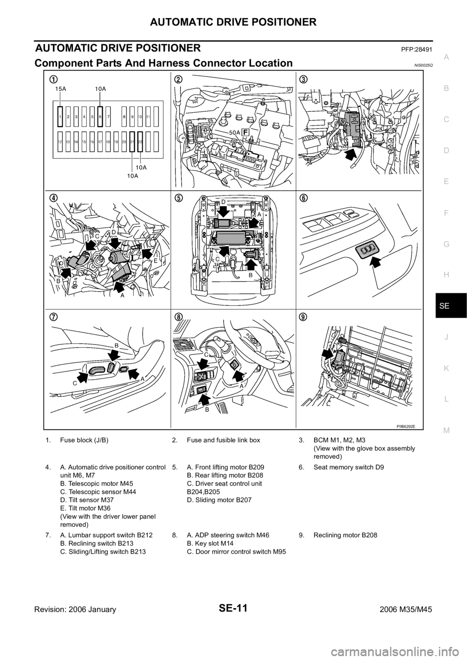
Component Parts And Harness Connector LocationNIS0025Q
PIIB6292E
1. Fuse block (J/B) 2. Fuse and fusible link box 3. BCM M1, M2, M3
(View with the glove box assembly
removed)
4. A. Automatic drive positioner control
unit M6, M7
B. Telescopic motor M45
C. Telescopic sensor M44
D. Tilt sensor M37
E. Tilt motor M36
(View with the driver lower panel
removed)5. A. Front lifting motor B209
B. Rear lifting motor B208
C. Driver seat control unit
B204,B205
D. Sliding motor B2076. Seat memory switch D9
7. A. Lumbar support switch B212
B. Reclining switch B213
C. Sliding/Lifting switch B2138. A. ADP steering switch M46
B. Key slot M14
C. Door mirror control switch M959. Reclining motor B208
Page 5193 of 5621

SE-12
AUTOMATIC DRIVE POSITIONER
Revision: 2006 January2006 M35/M45
System DescriptionNIS0025R
The system automatically moves the driver seat, steering and door mirror position by the driver seat con-
trol unit and the automatic drive positioner control unit. The driver seat control unit corresponds with the
automatic drive positioner control unit via UART communication. The driver seat control unit can store the
optimum driving positions (driver seat, steering and door mirror position) for 2 people. If the driver
changes, one-touch operation allows changing to the other driving position.
The driver seat, steering and door mirror position are adjusted automatically to the proper positions for the
driver in different ways: MEMORY OPERATION, EXITING OPERATION, ENTRY OPERATION and
INTELLIGENT KEY INTERLOCK OPERATION.
MANUAL OPERATION
The driving position (seat, steering and door mirror position) can be adjusted with the power seat switch, ADP
steering switch and door mirror control switch.
NOTE:
The door mirrors can be manually operated with the ignition switch in either ACC or ON.
MEMORY OPERATION
The driver seat control unit can store the optimum driving positions (seat, steering and door mirror position) for
2 people. If the front seat position is changed, one-touch (pressing desired memory switch for more than 0.5
second) operation allows changing to the other driving position.
Operation procedure
1. Turn ignition switch ON.
2. Press desired memory switch for 0.5 second. (Indicator LED illuminates.)
3. Driver seat, steering and door mirror will move to the memorized position.
(Indicator LED blinks during adjustment, then illuminates for 5 seconds.)
Operation Condition
If the following conditions are not satisfied, memory switch operation is not performed.
Ignition switch is in ON position.
Driver side power seat switch, ADP steering switch and door mirror control switch are not operated.
Seat memory switch and set switch are not operated.
Output malfunction is not detected.
CAN and UART communications are normal.
A/T selector lever position is in P position.
Detention switch malfunction is not detected.
[Detention switch malfunction is sensed when detention switch remains OFF, vehicle speed is higher than
7 km/H. (4 MPH).]
Input voltage from tilt sensor and telescopic sensor are normal.
NOTE:
The memory operation operates following order.
Function Description
Manual operationThe driving position (seat, steering and door mirror position) can be adjusted with
the power seat switch ADP steering switch or door mirror control switch.
Auto-
matic
operationMemory operation The seat, steering and door mirror move to the stored driving position by pushing
seat memory switch (1 or 2).
Entry/
Exiting
functionExiting operation At exit, the seat moves backward and the steering wheel moves upward.
Entry operationAt entry, the seat and steering wheel returns from exiting position to the previous
driving position before the exiting operation.
Intelligent Key interlock operationPerform memory operation, exiting operation and entry operation by pressing Intel-
ligent Key unlock button.
Page 5212 of 5621
AUTOMATIC DRIVE POSITIONER
SE-31
C
D
E
F
G
H
J
K
L
MA
B
SE
Revision: 2006 January2006 M35/M45
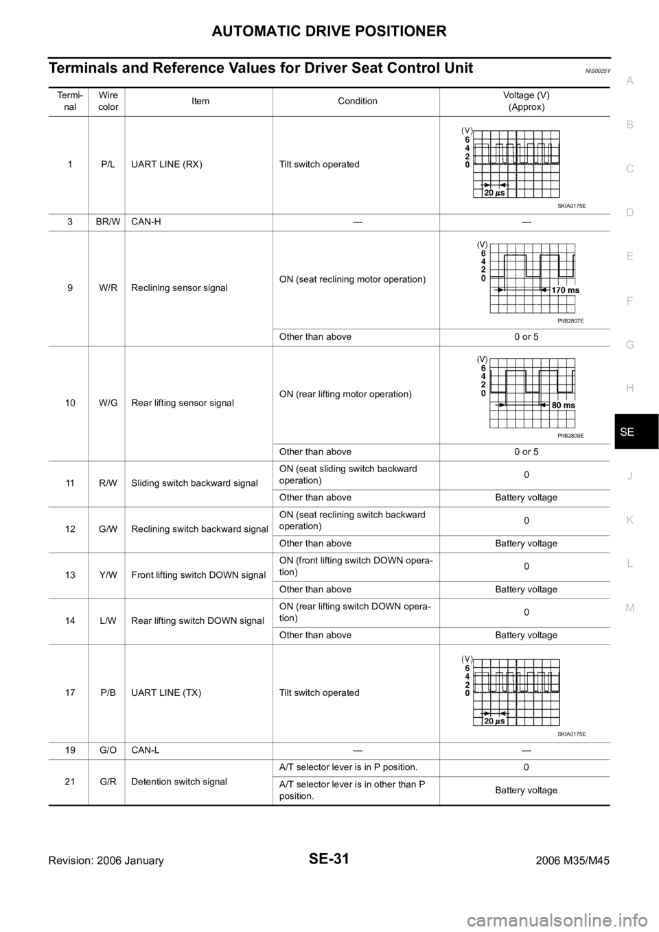
Terminals and Reference Values for Driver Seat Control UnitNIS0025Y
Te r m i -
nalWire
colorItem ConditionVoltage (V)
(Approx)
1 P/L UART LINE (RX) Tilt switch operated
3BR/WCAN-H — —
9 W/R Reclining sensor signalON (seat reclining motor operation)
Other than above 0 or 5
10 W/G Rear lifting sensor signalON (rear lifting motor operation)
Other than above 0 or 5
11 R/W Sliding switch backward signalON (seat sliding switch backward
operation)0
Other than above Battery voltage
12 G/W Reclining switch backward signalON (seat reclining switch backward
operation)0
Other than above Battery voltage
13 Y/W Front lifting switch DOWN signalON (front lifting switch DOWN opera-
tion)0
Other than above Battery voltage
14 L/W Rear lifting switch DOWN signalON (rear lifting switch DOWN opera-
tion)0
Other than above Battery voltage
17 P/B UART LINE (TX) Tilt switch operated
19 G/O CAN-L — —
21 G/R Detention switch signalA/T selector lever is in P position. 0
A/T selector lever is in other than P
position.Battery voltage
SKIA0175E
PIIB2807E
PIIB2809E
SKIA0175E