Page 5560 of 5621

TROUBLE DIAGNOSIS FOR SYMPTOMS
WT-35
C
D
F
G
H
I
J
K
L
MA
B
WT
Revision: 2006 January2006 M35/M45
TROUBLE DIAGNOSIS FOR SYMPTOMSPFP:00007
Inspection 1: Warning Lamp Does Not Come On When Ignition Switch Is Turned
On
NES000KH
1. CHECK SELF-DIAGNOSIS RESULTS
1. Turn ignition switch OFF.
2. Connect CONSULT-II and CONSULT-II CONVERTER to data link connector.
3. Turn ignition switch ON.
4. Touch “START (NISSAN BASED VHCL)” “AIR PRESSURE MONITOR” “SELF-DIAG RESULTS”.
–If AIR PRESSURE MONITOR is not displayed, print the “SELECT SYSTEM” screen. Then refer to LAN-7,
"Precautions When Using CONSULT-II" .
NOTE:
Just after starting engine, or turning ignition switch ON, it may not be displayed even if “START (NISSAN
BASED VHCL)” is touched. In this case, reconnect CONSULT-II and CONSULT-II CONVERTER.
5. Check display contents in self-diagnostic results.
Is
“CAN COMM CIRCUIT” displayed in the self-diagnosis display items?
YES >> Malfunction in CAN communication system. GO TO LAN-7, "Precautions When Using CONSULT-
II" .
NO >> GO TO 2.
2. CHECK COMBINATION METER
Check combination meter function.
OK or NG
OK >> GO TO 3.
NG >> Check combination meter. Refer to DI-18, "
Trouble Diagnosis" .
3. CHECK LOW TIRE PRESSURE WARNING LAMP
Disconnect low tire pressure warning control unit harness connector M19.
Does the warning lamp activate?
YES >> Replace low tire pressure warning control unit. Refer to WT-40, "Low Tire Pressure Warning Con-
trol Unit" .
NO >> Check combination meter and repair or replace.
Page 5573 of 5621

WW-6
FRONT WIPER AND WASHER SYSTEM
Revision: 2006 January2006 M35/M45
HIGH SPEED WIPER OPERATION
When wiper switch is in the HI position, BCM detects high speed wiper ON signal by BCM wiper switch read-
ing function.
BCM sends front wiper request signal (HI) with CAN communication line
from BCM terminals 39 and 40
to IPDM E/R terminals 49 and 50.
When IPDM E/R receives front wiper request signal (HI), it turns ON front wiper high relay (located in IPDM
E/R) and front wiper reverse relay (located in relay box-1), power is supplied
through IPDM E/R terminal 19
through front wiper reverse relay terminals 5 and 3
to front wiper motor terminal 1.
Ground is supplied
to front wiper motor terminal 2
to IPDM E/R terminal 31 and front wiper high relay and front wiper low relay
to IPDM E/R terminal 38
through grounds E22 and E43.
With power and ground supplied, the front wiper motor operates at high speed.
INTERMITTENT OPERATION
1. BCM detects ON/OFF status of intermittent operation dial position 1, 2 and 3 switched by wiper dial posi-
tion to judge wiper dial position status.
2. BCM calculates intermittent operation interval time (second) from the vehicle speed signal received by
combination meter through CAN communication line and the wiper dial position.
Unit: second
NOTE:
The value in the table can differ from the actual vehicle speed.
3. BCM switches front wiper request signal transmitted to IPDM E/R through CAN communication line from
STOP to LO once at intervals of intermittent operation time.
4. IPDM E/R receives front wiper request signal (LO) once to turn ON front wiper main relay located in IPDM
E/R. Then operates front wiper. IPDM E/R receives front wiper auto stop signal (stop) input from front
wiper motor to turn OFF front wiper motor relay. IPDM E/R switches front wiper auto stop signal transmit-
ted through CAN communication line from MOVE to STOP.
5. BCM receives front wiper auto stop signal (stop) to operate timer that determines intermittent operation
interval time till next front wiper motor operation.
Wiper dial positionIntermittent operation
interval timeStoppedVehicle speed; approx.
5 km/h (3.1 MPH) or
more to approx. 65 km/h
(40.4 MPH)Vehicle speed approx.
65 km/h (40.4 MPH)
or more
1 Short
Long10.40.2
2 2.510.6
3521.2
4 7.531.8
5 12.5 5 3
625106
740169.6
Page 5606 of 5621

FRONT WIPER AND WASHER SYSTEM
WW-39
C
D
E
F
G
H
I
J
L
MA
B
WW
Revision: 2006 January2006 M35/M45
6. CHECK IPDM E/R
With CONSULT-II
1. Connect IPDM E/R connector and front wiper motor connector.
2. Install front wiper reverse relay.
3. Select “IPDM E/R” on CONSULT-II. Select “ACTIVE TEST” on “SELECT DIAG MODE” screen.
4. Select “FRONT WIPER” on “SELECT TEST ITEM” screen.
5. Touch “HI” screen.
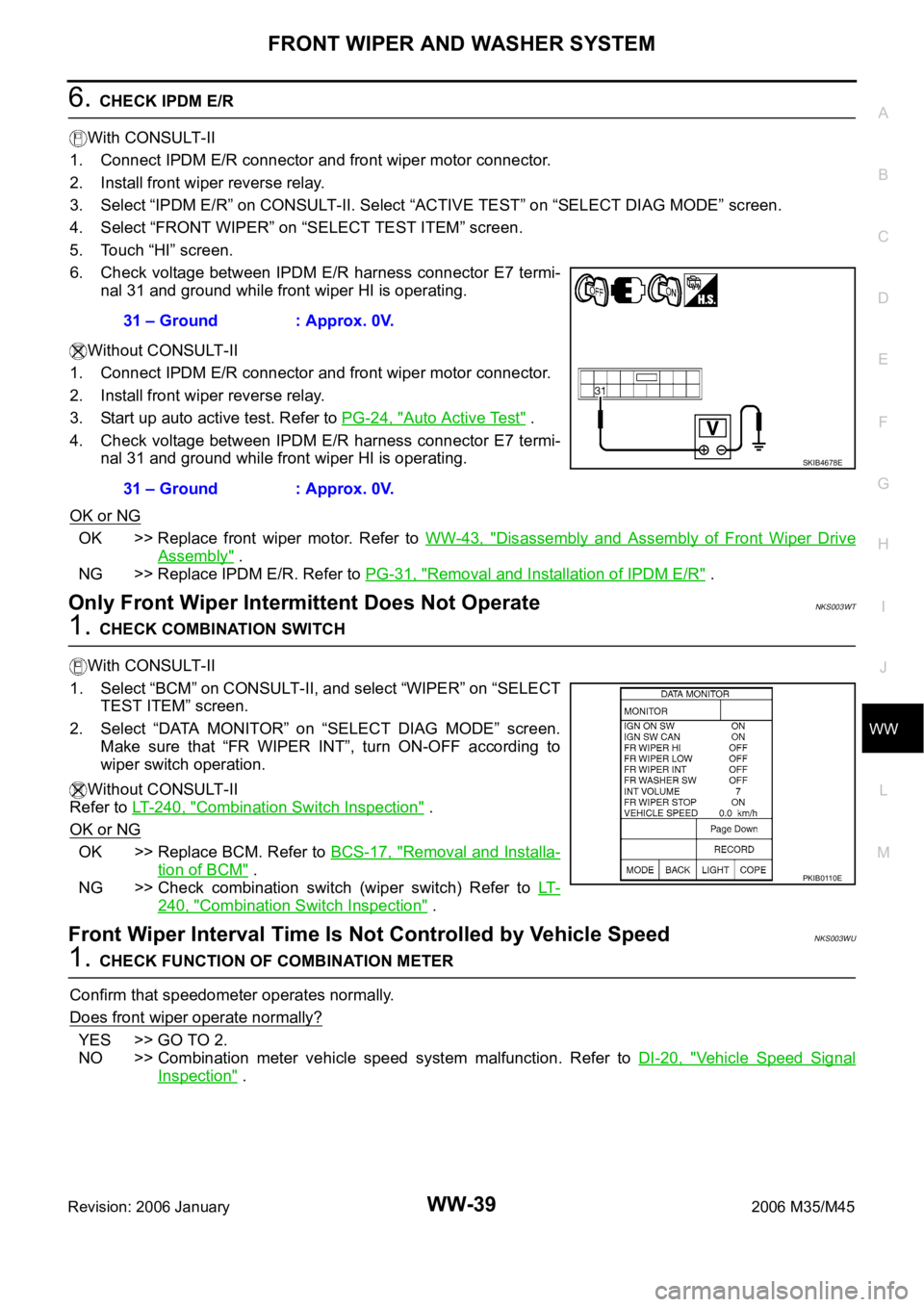
6. Check voltage between IPDM E/R harness connector E7 termi-
nal 31 and ground while front wiper HI is operating.
Without CONSULT-II
1. Connect IPDM E/R connector and front wiper motor connector.
2. Install front wiper reverse relay.
3. Start up auto active test. Refer to PG-24, "
Auto Active Test" .
4. Check voltage between IPDM E/R harness connector E7 termi-
nal 31 and ground while front wiper HI is operating.
OK or NG
OK >> Replace front wiper motor. Refer to WW-43, "Disassembly and Assembly of Front Wiper Drive
Assembly" .
NG >> Replace IPDM E/R. Refer to PG-31, "
Removal and Installation of IPDM E/R" .
Only Front Wiper Intermittent Does Not OperateNKS003WT
1. CHECK COMBINATION SWITCH
With CONSULT-II
1. Select “BCM” on CONSULT-II, and select “WIPER” on “SELECT
TEST ITEM” screen.
2. Select “DATA MONITOR” on “SELECT DIAG MODE” screen.
Make sure that “FR WIPER INT”, turn ON-OFF according to
wiper switch operation.
Without CONSULT-II
Refer to LT-240, "
Combination Switch Inspection" .
OK or NG
OK >> Replace BCM. Refer to BCS-17, "Removal and Installa-
tion of BCM" .
NG >> Check combination switch (wiper switch) Refer to LT-
240, "Combination Switch Inspection" .
Front Wiper Interval Time Is Not Controlled by Vehicle SpeedNKS003WU
1. CHECK FUNCTION OF COMBINATION METER
Confirm that speedometer operates normally.
Does front wiper operate normally?
YES >> GO TO 2.
NO >> Combination meter vehicle speed system malfunction. Refer to DI-20, "
Vehicle Speed Signal
Inspection" . 31 – Ground : Approx. 0V.
31 – Ground : Approx. 0V.
SKIB4678E
PKIB0110E
Page 5607 of 5621

WW-40
FRONT WIPER AND WASHER SYSTEM
Revision: 2006 January2006 M35/M45
2. CHECK CAN COMMUNICATION BETWEEN BCM AND COMBINATION METER
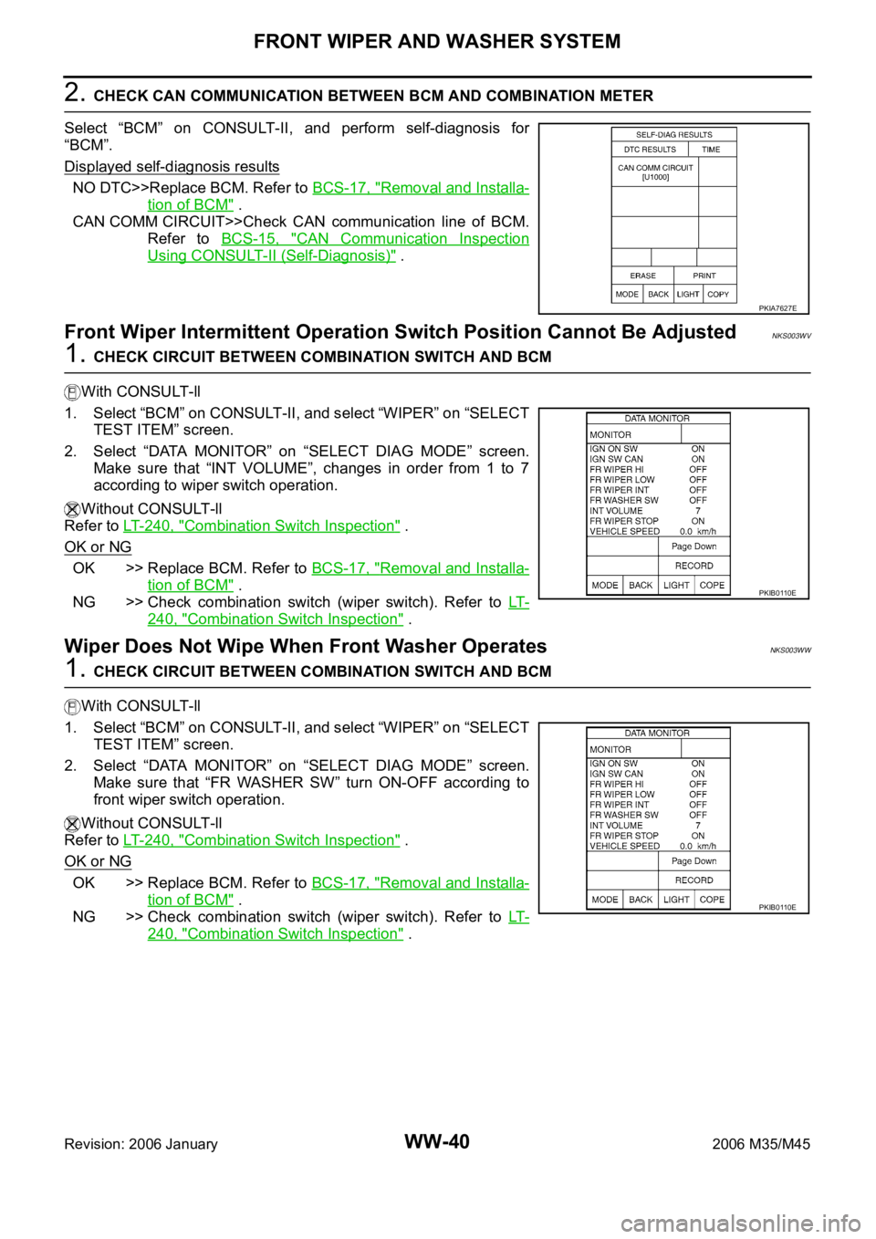
Select “BCM” on CONSULT-II, and perform self-diagnosis for
“BCM”.
Displayed self
-diagnosis results
NO DTC>>Replace BCM. Refer to BCS-17, "Removal and Installa-
tion of BCM" .
CAN COMM CIRCUIT>>Check CAN communication line of BCM.
Refer to BCS-15, "
CAN Communication Inspection
Using CONSULT-II (Self-Diagnosis)" .
Front Wiper Intermittent Operation Switch Position Cannot Be AdjustedNKS003WV
1. CHECK CIRCUIT BETWEEN COMBINATION SWITCH AND BCM
With CONSULT-ll
1. Select “BCM” on CONSULT-II, and select “WIPER” on “SELECT
TEST ITEM” screen.
2. Select “DATA MONITOR” on “SELECT DIAG MODE” screen.
Make sure that “INT VOLUME”, changes in order from 1 to 7
according to wiper switch operation.
Without CONSULT-ll
Refer to LT- 2 4 0 , "
Combination Switch Inspection" .
OK or NG
OK >> Replace BCM. Refer to BCS-17, "Removal and Installa-
tion of BCM" .
NG >> Check combination switch (wiper switch). Refer to LT-
240, "Combination Switch Inspection" .
Wiper Does Not Wipe When Front Washer OperatesNKS003WW
1. CHECK CIRCUIT BETWEEN COMBINATION SWITCH AND BCM
With CONSULT-ll
1. Select “BCM” on CONSULT-II, and select “WIPER” on “SELECT
TEST ITEM” screen.
2. Select “DATA MONITOR” on “SELECT DIAG MODE” screen.
Make sure that “FR WASHER SW” turn ON-OFF according to
front wiper switch operation.
Without CONSULT-ll
Refer to LT- 2 4 0 , "
Combination Switch Inspection" .
OK or NG
OK >> Replace BCM. Refer to BCS-17, "Removal and Installa-
tion of BCM" .
NG >> Check combination switch (wiper switch). Refer to LT-
240, "Combination Switch Inspection" .
PKIA7627E
PKIB0110E
PKIB0110E