Page 935 of 5621
BCS-14
BCM (BODY CONTROL MODULE)
Revision: 2006 January2006 M35/M45
4. Select the desired part to be diagnosed on the “SELECT TEST
ITEM” screen.
ITEMS OF EACH PART
: Applicable
NOTE:
CONSULT-II displays systems equipped in the vehicle.
PKIC0325E
System and item CONSULT-II displayDiagnostic test mode (Inspection by part)
WORK
SUPPORTSELFDIAG
RESULTSDATA
MONITORCAN DIAG
SUPPORT
MNTRACTIVE
TESTECU
PA R T
NUMBER
BCM BCM
Power door lock system DOOR LOCK
Rear window defogger REAR DEFOGGER
Warning chime BUZZER
Room lamp timer INT LAMP
Headlamp HEAD LAMP
Wiper WIPER
Turn signal lamp
Hazard lampFLASHER
Intelligent Key system INTELLIGENT KEY
Combination switch COMB SW
IVIS IMMU
Room lamp battery saver BATTERY SAVER
Trunk lid TRUNK
Vehicle security system THEFT ALM
Retained power control RETAINED PWR
Oil pressure switch SIGNAL BUFFER
Panic system PANIC ALARM
Page 1278 of 5621

PRECAUTIONS
BR-3
C
D
E
G
H
I
J
K
L
MA
B
BR
Revision: 2006 January2006 M35/M45
PRECAUTIONSPFP:00001
Precautions for Supplemental Restraint System (SRS) “AIR BAG” and “SEAT
BELT PRE-TENSIONER”
NFS000ON
The Supplemental Restraint System such as “AIR BAG” and “SEAT BELT PRE-TENSIONER”, used along
with a front seat belt, helps to reduce the risk or severity of injury to the driver and front passenger for certain
types of collision. This system includes seat belt switch inputs and dual stage front air bag modules. The SRS
system uses the seat belt switches to determine the front air bag deployment, and may only deploy one front
air bag, depending on the severity of a collision and whether the front occupants are belted or unbelted.
Information necessary to service the system safely is included in the SRS and SB section of this Service Man-
ual.
WAR NING :
To avoid rendering the SRS inoperative, which could increase the risk of personal injury or death
in the event of a collision which would result in air bag inflation, all maintenance must be per-
formed by an authorized NISSAN/INFINITI dealer.
Improper maintenance, including incorrect removal and installation of the SRS, can lead to per-
sonal injury caused by unintentional activation of the system. For removal of Spiral Cable and Air
Bag Module, see the SRS section.
Do not use electrical test equipment on any circuit related to the SRS unless instructed to in this
Service Manual. SRS wiring harnesses can be identified by yellow and/or orange harnesses or
harness connectors.
Precautions for Procedures without Cowl Top CoverNFS000OO
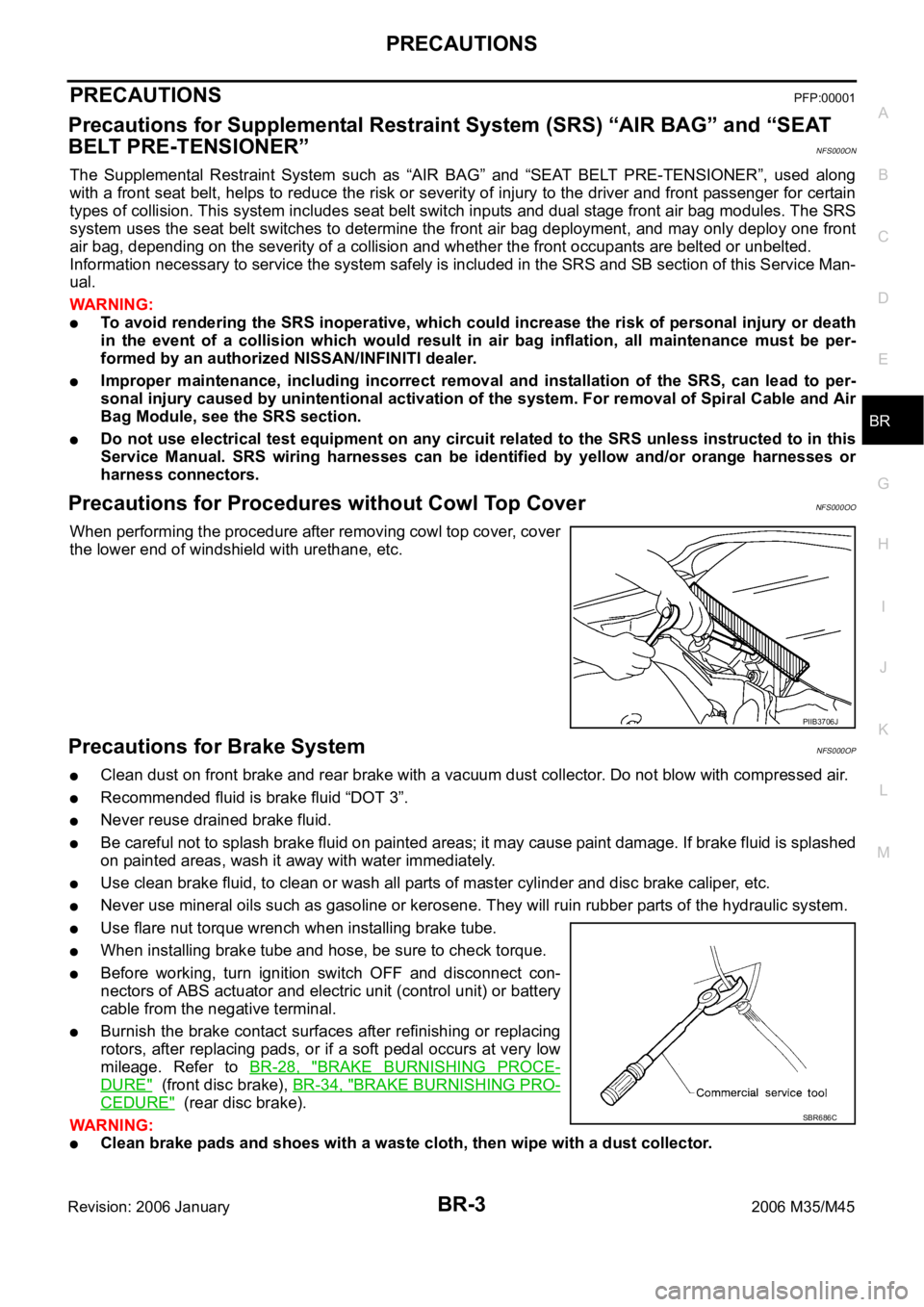
When performing the procedure after removing cowl top cover, cover
the lower end of windshield with urethane, etc.
Precautions for Brake SystemNFS000OP
Clean dust on front brake and rear brake with a vacuum dust collector. Do not blow with compressed air.
Recommended fluid is brake fluid “DOT 3”.
Never reuse drained brake fluid.
Be careful not to splash brake fluid on painted areas; it may cause paint damage. If brake fluid is splashed
on painted areas, wash it away with water immediately.
Use clean brake fluid, to clean or wash all parts of master cylinder and disc brake caliper, etc.
Never use mineral oils such as gasoline or kerosene. They will ruin rubber parts of the hydraulic system.
Use flare nut torque wrench when installing brake tube.
When installing brake tube and hose, be sure to check torque.
Before working, turn ignition switch OFF and disconnect con-
nectors of ABS actuator and electric unit (control unit) or battery
cable from the negative terminal.
Burnish the brake contact surfaces after refinishing or replacing
rotors, after replacing pads, or if a soft pedal occurs at very low
mileage. Refer to BR-28, "
BRAKE BURNISHING PROCE-
DURE" (front disc brake), BR-34, "BRAKE BURNISHING PRO-
CEDURE" (rear disc brake).
WAR NING :
Clean brake pads and shoes with a waste cloth, then wipe with a dust collector.
PIIB3706J
SBR686C
Page 1285 of 5621

BR-10
BRAKE FLUID
Revision: 2006 January2006 M35/M45
BRAKE FLUIDPFP:KN100
On-Board Inspection NFS000OU
CHECKING BRAKE FLUID LEVEL
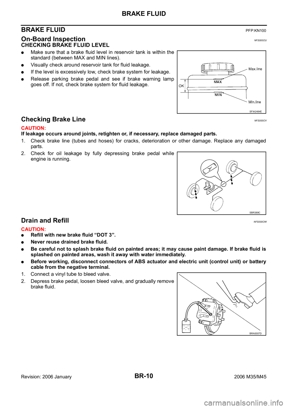
Make sure that a brake fluid level in reservoir tank is within the
standard (between MAX and MIN lines).
Visually check around reservoir tank for fluid leakage.
If the level is excessively low, check brake system for leakage.
Release parking brake pedal and see if brake warning lamp
goes off. If not, check brake system for fluid leakage.
Checking Brake LineNFS000OV
CAUTION:
If leakage occurs around joints, retighten or, if necessary, replace damaged parts.
1. Check brake line (tubes and hoses) for cracks, deterioration or other damage. Replace any damaged
parts.
2. Check for oil leakage by fully depressing brake pedal while
engine is running.
Drain and RefillNFS000OW
CAUTION:
Refill with new brake fluid “DOT 3”.
Never reuse drained brake fluid.
Be careful not to splash brake fluid on painted areas; it may cause paint damage. If brake fluid is
splashed on painted areas, wash it away with water immediately.
Before working, disconnect connectors of ABS actuator and electric unit (control unit) or battery
cable from the negative terminal.
1. Connect a vinyl tube to bleed valve.
2. Depress brake pedal, loosen bleed valve, and gradually remove
brake fluid.
SFIA2484E
SBR389C
BRA0007D
Page 1291 of 5621
BR-16
BRAKE MASTER CYLINDER
Revision: 2006 January2006 M35/M45
Disassembly and AssemblyNFS000P4
COMPONENTS
Disassembly and AssemblyNFS000P5
DISASSEMBLY
CAUTION:
Master cylinder cannot be disassembled.
Remove reservoir tank only when absolutely necessary.
When securing master cylinder assembly in a vise, be sure not to over-tighten.
When securing in a vise use copper plates or cloth to protect the flange.
1. Using a pin punch [commercial service tool: diameter approxi-
mately 4 mm (0.16 in)], remove mounting pin on reservoir tank.
2. Remove reservoir tank and grommet from cylinder body.
1. Reservoir cap 2. Oil strainer 3. Reservoir tank
4. Grommet 5. Pin 6. Master cylinder assembly
7. O-ring 8. Brake fluid level switch connector
: PBC (Poly Butyl Cuprysil) grease
or silicone-based grease: Brake fluid
Refer to GI section for symbol marks except in the above.
SFIA2955E
BRA0559D
Page 1292 of 5621
BRAKE MASTER CYLINDER
BR-17
C
D
E
G
H
I
J
K
L
MA
B
BR
Revision: 2006 January2006 M35/M45
ASSEMBLY
CAUTION:
Never use mineral oils such as kerosene, gasoline during the cleaning and assembly process.
Do not drop parts. If a part is dropped, do not use it.
1. Apply brake fluid to the grommet and attach it to the cylinder body.
CAUTION:
Do not reuse grommet.
2. Install reservoir tank onto the cylinder body.
3. Secure master cylinder assembly into a vise with a chamfered
pin insert hole on cylinder body facing upward.
4. Tilt reservoir tank as shown in the figure and insert mounting pin.
Return reservoir tank to a upright position when mounting pin
passes through the pinhole in the cylinder body. Push the
mounting pin to the opposite pinhole of the reservoir tank so that
it is the same conditions as the insertion side.
CAUTION:
Be sure to fix the flange part with the brake tube installa-
tion side of cylinder body up.
Do not reuse mounting pin.
PFIA0505J
BRA0559D
Page 1297 of 5621
BR-22
VACUUM LINES
Revision: 2006 January2006 M35/M45
Removal and InstallationNFS000P9
CAUTION:
Because vacuum hose contains a check valve, it must be
installed in the correct position. Refer to the stamp to con-
firm correct installation. Brake booster will not operate nor-
mally if the hose is installed in the wrong direction.
Insert vacuum hose at least 24 mm (0.94 in).
Do not use lubricating oil during assembly.
InspectionNFS000PA
VISUAL INSPECTION
Check for correct assembly, damage and deterioration.
CHECK VALVE INSPECTION
Airtightness Inspection
Use a handy vacuum pump to check.
Replace vacuum hose assembly if vacuum hose and check
valve are malfunctioning.
SBR225B
When connected to the booster side (1):
Vacuum should decrease within 1.3 kPa (10
mmHg, 0.39 inHg) for 15 seconds under a vacuum
of
66.7 kPa (500 mmHg, 19.69 inHg).
When connected to the engine side (2):
Vacuum should not exist.
SFIA0210E
Page 1300 of 5621

FRONT DISC BRAKE
BR-25
C
D
E
G
H
I
J
K
L
MA
B
BR
Revision: 2006 January2006 M35/M45
Removal and Installation of Brake Caliper AssemblyNFS000PE
REMOVAL
1. Remove tires from vehicle with power tool.
2. Fasten disc rotor using wheel nut.
3. Drain brake fluid. Refer to BR-10, "
Drain and Refill" .
4. Remove union bolt, and then disconnect brake hose from caliper assembly.
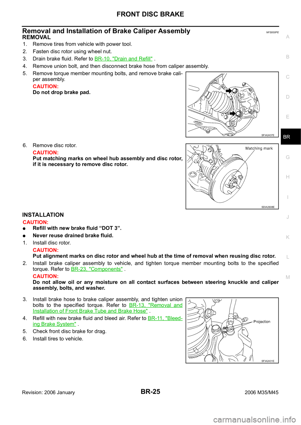
5. Remove torque member mounting bolts, and remove brake cali-
per assembly.
CAUTION:
Do not drop brake pad.
6. Remove disc rotor.
CAUTION:
Put matching marks on wheel hub assembly and disc rotor,
if it is necessary to remove disc rotor.
INSTALLATION
CAUTION:
Refill with new brake fluid “DOT 3”.
Never reuse drained brake fluid.
1. Install disc rotor.
CAUTION:
Put alignment marks on disc rotor and wheel hub at the time of removal when reusing disc rotor.
2. Install brake caliper assembly to vehicle, and tighten torque member mounting bolts to the specified
torque. Refer to BR-23, "
Components" .
CAUTION:
Do not allow oil or any moisture on all contact surfaces between steering knuckle and caliper
assembly, bolts, and washer.
3. Install brake hose to brake caliper assembly, and tighten union
bolts to the specified torque. Refer to BR-13, "
Removal and
Installation of Front Brake Tube and Brake Hose" .
4. Refill with new brake fluid and bleed air. Refer to BR-11, "
Bleed-
ing Brake System" .
5. Check front disc brake for drag.
6. Install tires to vehicle.
SFIA2437E
SDIA2608E
SFIA2431E
Page 1301 of 5621

BR-26
FRONT DISC BRAKE
Revision: 2006 January2006 M35/M45
Disassembly and Assembly of Brake Caliper AssemblyNFS000PF
NOTE:
Do not remove torque member, pads, shims, shim covers, and pad retainers when disassembling and assem-
bling cylinder body assembly.
DISASSEMBLY
1. Remove sliding pin bolt, and then remove cylinder body from torque member.
CAUTION:
Do not drop pads, shims, shim cover and pad retainers from torque member.
2. Remove sliding pins and sliding pin boots from torque member.
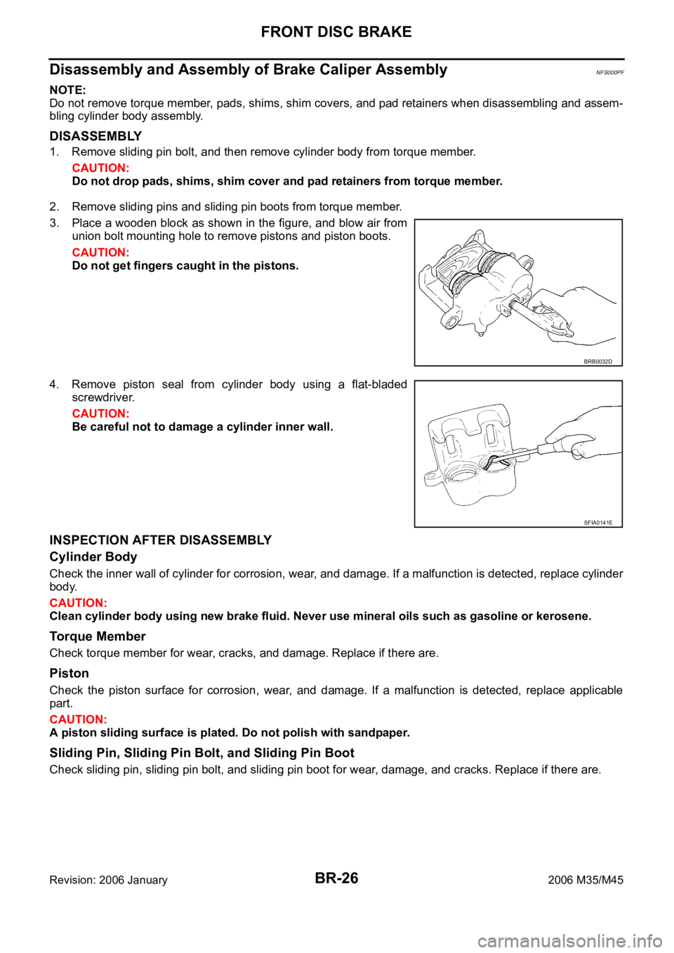
3. Place a wooden block as shown in the figure, and blow air from
union bolt mounting hole to remove pistons and piston boots.
CAUTION:
Do not get fingers caught in the pistons.
4. Remove piston seal from cylinder body using a flat-bladed
screwdriver.
CAUTION:
Be careful not to damage a cylinder inner wall.
INSPECTION AFTER DISASSEMBLY
Cylinder Body
Check the inner wall of cylinder for corrosion, wear, and damage. If a malfunction is detected, replace cylinder
body.
CAUTION:
Clean cylinder body using new brake fluid. Never use mineral oils such as gasoline or kerosene.
Torque Member
Check torque member for wear, cracks, and damage. Replace if there are.
Piston
Check the piston surface for corrosion, wear, and damage. If a malfunction is detected, replace applicable
part.
CAUTION:
A piston sliding surface is plated. Do not polish with sandpaper.
Sliding Pin, Sliding Pin Bolt, and Sliding Pin Boot
Check sliding pin, sliding pin bolt, and sliding pin boot for wear, damage, and cracks. Replace if there are.
BRB0032D
SFIA0141E