2006 INFINITI M35 stall
[x] Cancel search: stallPage 5564 of 5621

REMOVAL AND INSTALLATION
WT-39
C
D
F
G
H
I
J
K
L
MA
B
WT
Revision: 2006 January2006 M35/M45
REMOVAL AND INSTALLATIONPFP:00000
Tr a n s m i t t e rNES000KM
REMOVAL
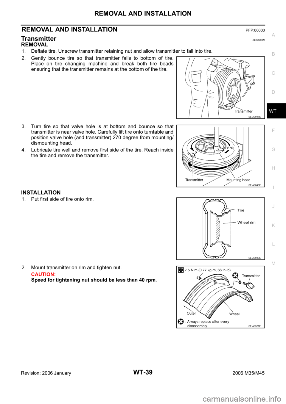
1. Deflate tire. Unscrew transmitter retaining nut and allow transmitter to fall into tire.
2. Gently bounce tire so that transmitter falls to bottom of tire.
Place on tire changing machine and break both tire beads
ensuring that the transmitter remains at the bottom of the tire.
3. Turn tire so that valve hole is at bottom and bounce so that
transmitter is near valve hole. Carefully lift tire onto turntable and
position valve hole (and transmitter) 270 degree from mounting/
dismounting head.
4. Lubricate tire well and remove first side of the tire. Reach inside
the tire and remove the transmitter.
INSTALLATION
1. Put first side of tire onto rim.
2. Mount transmitter on rim and tighten nut.
CAUTION:
Speed for tightening nut should be less than 40 rpm.
SEIA0047E
SEIA0048E
SEIA0049E
SEIA0521E
Page 5565 of 5621

WT-40
REMOVAL AND INSTALLATION
Revision: 2006 January2006 M35/M45
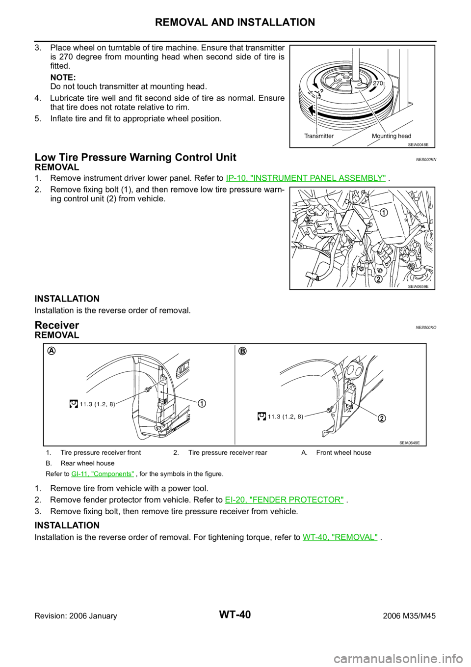
3. Place wheel on turntable of tire machine. Ensure that transmitter
is 270 degree from mounting head when second side of tire is
fitted.
NOTE:
Do not touch transmitter at mounting head.
4. Lubricate tire well and fit second side of tire as normal. Ensure
that tire does not rotate relative to rim.
5. Inflate tire and fit to appropriate wheel position.
Low Tire Pressure Warning Control UnitNES000KN
REMOVAL
1. Remove instrument driver lower panel. Refer to IP-10, "INSTRUMENT PANEL ASSEMBLY" .
2. Remove fixing bolt (1), and then remove low tire pressure warn-
ing control unit (2) from vehicle.
INSTALLATION
Installation is the reverse order of removal.
ReceiverNES000KO
REMOVAL
1. Remove tire from vehicle with a power tool.
2. Remove fender protector from vehicle. Refer to EI-20, "
FENDER PROTECTOR" .
3. Remove fixing bolt, then remove tire pressure receiver from vehicle.
INSTALLATION
Installation is the reverse order of removal. For tightening torque, refer to WT-40, "REMOVAL" .
SEIA0048E
SEIA0659E
1. Tire pressure receiver front 2. Tire pressure receiver rear A. Front wheel house
B. Rear wheel house
Refer to GI-11, "
Components" , for the symbols in the figure.
SEIA0649E
Page 5568 of 5621

WW-1
WIPER, WASHER & HORN
K ELECTRICAL
CONTENTS
C
D
E
F
G
H
I
J
L
M
SECTION WW
A
B
WW
Revision: 2006 January2006 M35/M45
WIPER, WASHER & HORN
PRECAUTION ............................................................ 3
Precautions for Supplemental Restraint System
(SRS) “AIR BAG” and “SEAT BELT PRE-TEN-
SIONER” .................................................................. 3
FRONT WIPER AND WASHER SYSTEM .................. 4
Components Parts and Harness Connector Loca-
tion ........................................................................... 4
System Description .................................................. 4
OUTLINE ............................................................... 5
LOW SPEED WIPER OPERATION ...................... 5
HIGH SPEED WIPER OPERATION ..................... 6
INTERMITTENT OPERATION .............................. 6
AUTO STOP OPERATION .................................... 7
WASHER OPERATION ......................................... 7
MIST OPERATION ................................................ 7
FAIL-SAFE FUNCTION ......................................... 7
COMBINATION SWITCH READING FUNCTION ..... 8
CAN Communication System Description ............... 11
CAN Communication Unit ....................................... 11
Schematic .............................................................. 12
Wiring Diagram — WIPER — ................................ 13
Terminals and Reference Values for BCM ............. 17
Terminals and Reference Values for IPDM E/R ..... 21
How to Perform Trouble Diagnoses ....................... 21
Preliminary Check .................................................. 22
CHECK POWER SUPPLY AND GROUND CIR-
CUIT .................................................................... 22
CONSULT-II Functions (BCM) ............................... 23
CONSULT-II BASIC OPERATION ....................... 23
WORK SUPPORT ............................................... 24
DATA MONITOR ................................................. 24
ACTIVE TEST ..................................................... 25
CONSULT-II Functions (IPDM E/R) ....................... 26
CONSULT-II BASIC OPERATION ....................... 26
DATA MONITOR ................................................. 27
ACTIVE TEST ..................................................... 27
Front Wiper Does Not Operate .............................. 28
Front Wiper Does Not Return to Stop Position (After
Front Wiper Operate for 10 Seconds, They Stop for
20 Seconds, and After Repeating the Operations Five Times, They Become Inoperative) .................. 31
Front Wiper Does Not Return to Stop Position When
Front Wiper Motor Operates at Low Speed (After
Front Wiper Operate for 10 Seconds, They Stop for
20 Seconds, and After Repeating the Operations
Five Times, They Become Inoperative) .................. 33
Front Wiper Does Not Return to Stop Position When
Front Wiper Motor Operates at HIGH Speed (After
Front Wiper Operate for 10 Seconds, They Stop for
20 Seconds, and After Repeating the Operations
Five Times, They Become Inoperative) .................. 34
Only Front Wiper LO Does Not Operate ................. 36
Only Front Wiper HI Does Not Operate .................. 37
Only Front Wiper Intermittent Does Not Operate ... 39
Front Wiper Interval Time Is Not Controlled by Vehi-
cle Speed ................................................................ 39
Front Wiper Intermittent Operation Switch Position
Cannot Be Adjusted .............................................
... 40
Wiper Does Not Wipe When Front Washer Operates
... 40
Front Wiper Does Not Stop ..................................... 41
Removal and Installation of Front Wiper Arms,
Adjustment of Wiper Arms Stop Location ............... 42
REMOVAL ........................................................
... 42
INSTALLATION ................................................... 42
ADJUSTMENT .................................................... 42
Removal and Installation of Front Wiper Drive
Assembly ................................................................ 43
REMOVAL ........................................................
... 43
INSTALLATION ................................................... 43
Disassembly and Assembly of Front Wiper Drive
Assembly ................................................................ 43
DISASSEMBLY ................................................... 44
ASSEMBLY ......................................................... 44
Washer Nozzle Adjustment .................................... 44
Washer Tube Layout .............................................. 45
Removal and Installation of Front Washer Nozzle ... 45
REMOVAL ........................................................
... 45
INSTALLATION ................................................... 45
Inspection for Washer Nozzle ................................. 46
Page 5569 of 5621

WW-2Revision: 2006 January2006 M35/M45 CHECK VALVE INSPECTION ............................. 46
Inspection of Front Wiper and Washer Switch Circuit ... 46
Removal and Installation of Front Wiper and Washer
Switch ..................................................................... 46
REMOVAL ........................................................
... 46
INSTALLATION .................................................... 46
Removal and Installation of Washer Tank .............. 47
REMOVAL ........................................................
... 47
INSTALLATION .................................................... 47
Removal and Installation of Washer Pump ............. 48
REMOVAL ........................................................
... 48
INSTALLATION .................................................... 48
CIGARETTE LIGHTER ............................................. 49
Wiring Diagram — CIGAR — ................................. 49
Removal and Installation ........................................ 50
REMOVAL ........................................................
... 50
INSTALLATION .................................................... 50POWER SOCKET ..................................................... 51
Wiring Diagram — P/SCKT — ................................ 51
Removal and Installation of Center Console Box
Power Socket .......................................................... 52
REMOVAL ............................................................ 52
INSTALLATION .................................................... 52
Removal and Installation of Center Console Box
Rear Side Power Socket ......................................... 52
REMOVAL ............................................................ 52
INSTALLATION .................................................... 52
HORN ........................................................................ 53
Wiring Diagram — HORN — .................................. 53
Removal and Installation ......................................... 54
REMOVAL ............................................................ 54
INSTALLATION .................................................... 54
Page 5570 of 5621

PRECAUTION
WW-3
C
D
E
F
G
H
I
J
L
MA
B
WW
Revision: 2006 January2006 M35/M45
PRECAUTION PFP:00011
Precautions for Supplemental Restraint System (SRS) “AIR BAG” and “SEAT
BELT PRE-TENSIONER”
NKS003WA
The Supplemental Restraint System such as “AIR BAG” and “SEAT BELT PRE-TENSIONER”, used along
with a front seat belt, helps to reduce the risk or severity of injury to the driver and front passenger for certain
types of collision. This system includes seat belt switch inputs and dual stage front air bag modules. The SRS
system uses the seat belt switches to determine the front air bag deployment, and may only deploy one front
air bag, depending on the severity of a collision and whether the front occupants are belted or unbelted.
Information necessary to service the system safely is included in the SRS and SB section of this Service Man-
ual.
WAR NING :
To avoid rendering the SRS inoperative, which could increase the risk of personal injury or death
in the event of a collision which would result in air bag inflation, all maintenance must be per-
formed by an authorized NISSAN/INFINITI dealer.
Improper maintenance, including incorrect removal and installation of the SRS, can lead to per-
sonal injury caused by unintentional activation of the system. For removal of Spiral Cable and Air
Bag Module, see the SRS section.
Do not use electrical test equipment on any circuit related to the SRS unless instructed to in this
Service Manual. SRS wiring harnesses can be identified by yellow and/or orange harnesses or
harness connectors.
Page 5589 of 5621

WW-22
FRONT WIPER AND WASHER SYSTEM
Revision: 2006 January2006 M35/M45
Preliminary CheckNKS003WK
CHECK POWER SUPPLY AND GROUND CIRCUIT
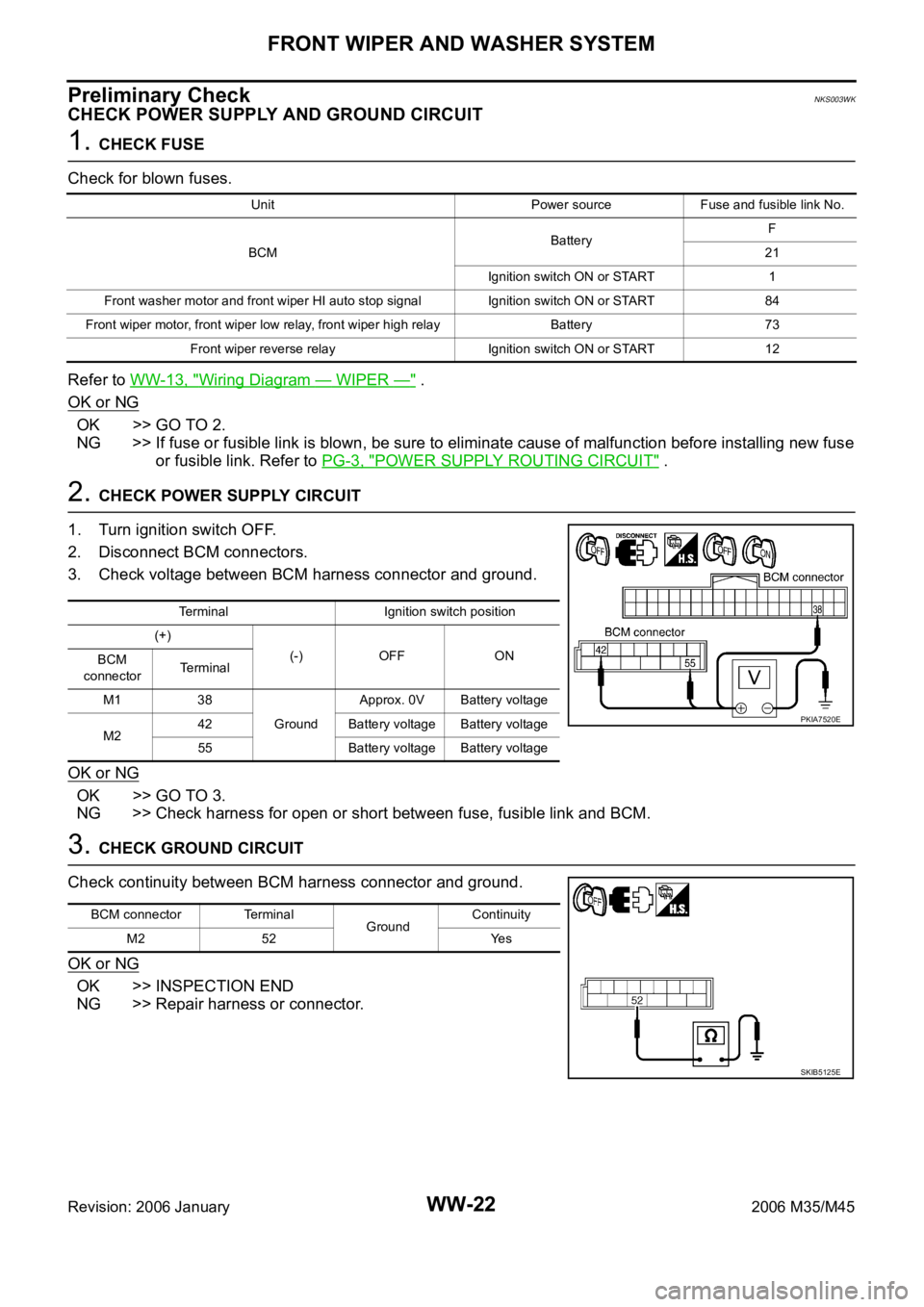
1. CHECK FUSE
Check for blown fuses.
Refer to WW-13, "
Wiring Diagram — WIPER —" .
OK or NG
OK >> GO TO 2.
NG >> If fuse or fusible link is blown, be sure to eliminate cause of malfunction before installing new fuse
or fusible link. Refer to PG-3, "
POWER SUPPLY ROUTING CIRCUIT" .
2. CHECK POWER SUPPLY CIRCUIT
1. Turn ignition switch OFF.
2. Disconnect BCM connectors.
3. Check voltage between BCM harness connector and ground.
OK or NG
OK >> GO TO 3.
NG >> Check harness for open or short between fuse, fusible link and BCM.
3. CHECK GROUND CIRCUIT
Check continuity between BCM harness connector and ground.
OK or NG
OK >> INSPECTION END
NG >> Repair harness or connector.
Unit Power source Fuse and fusible link No.
BCMBatteryF
21
Ignition switch ON or START 1
Front washer motor and front wiper HI auto stop signal Ignition switch ON or START 84
Front wiper motor, front wiper low relay, front wiper high relayBattery 73
Front wiper reverse relay Ignition switch ON or START 12
Terminal Ignition switch position
(+)
(-) OFF ON
BCM
connectorTerminal
M1 38
GroundApprox. 0V Battery voltage
M242 Battery voltage Battery voltage
55 Battery voltage Battery voltage
PKIA7520E
BCM connector Terminal
GroundContinuity
M2 52 Yes
SKIB5125E
Page 5595 of 5621

WW-28
FRONT WIPER AND WASHER SYSTEM
Revision: 2006 January2006 M35/M45
Front Wiper Does Not OperateNKS003WN
CAUTION:
During IPDM E/R fail-safe control, front wipers may not operate. Refer to PG-18, "CAN COMMUNI-
CATION LINE CONTROL" in “PG IPDM E/R” to make sure that it is not in fail-safe status.
1. ACTIVE TEST
With CONSULT-II
1. Select “IPDM E/R” by CONSULT-II, and select “ACTIVE TEST”
on “SELECT DIAG MODE” screen.
2. Select “FRONT WIPER” on “SELECT TEST ITEM” screen.
3. Touch “LO” or “HI” screen.
Without CONSULT-II
Start up auto active test. Refer to PG-24, "
Auto Active Test" .
Does front wiper operate normally?
YES >> GO TO 2.
NO >> GO TO 4.
2. CHECK CIRCUIT BETWEEN COMBINATION SWITCH AND BCM
With CONSULT-II
1. Select “BCM” on CONSULT-II, and select “WIPER” on “SELECT
TEST ITEM” screen.
2. Select “DATA MONITOR” on “SELECT DIAG MODE” screen.
Make sure that “FR WIPER INT”, “FR WIPER LOW”, and “FR
WIPER HI” turn ON-OFF according to wiper switch operation.
Without CONSULT-II
Refer to LT- 2 4 0 , "
Combination Switch Inspection" .
OK or NG
OK >> GO TO 3.
NG >> Check combination switch (wiper switch). Refer to LT-
240, "Combination Switch Inspection" .
3. CHECK CIRCUIT BETWEEN IPDM E/R AND BCM
Select “BCM” on CONSULT-II, and perform self-diagnosis for
“BCM”.
Displayed self
-diagnosis results
NO DTC>>Replace BCM. Refer to BCS-17, "Removal and Installa-
tion of BCM" .
CAN COMM CIRCUIT>>Check CAN communication line of BCM.
Refer to BCS-15, "
CAN Communication Inspection
Using CONSULT-II (Self-Diagnosis)" .
SKIA3486E
PKIB0110E
PKIA7627E
Page 5598 of 5621

FRONT WIPER AND WASHER SYSTEM
WW-31
C
D
E
F
G
H
I
J
L
MA
B
WW
Revision: 2006 January2006 M35/M45
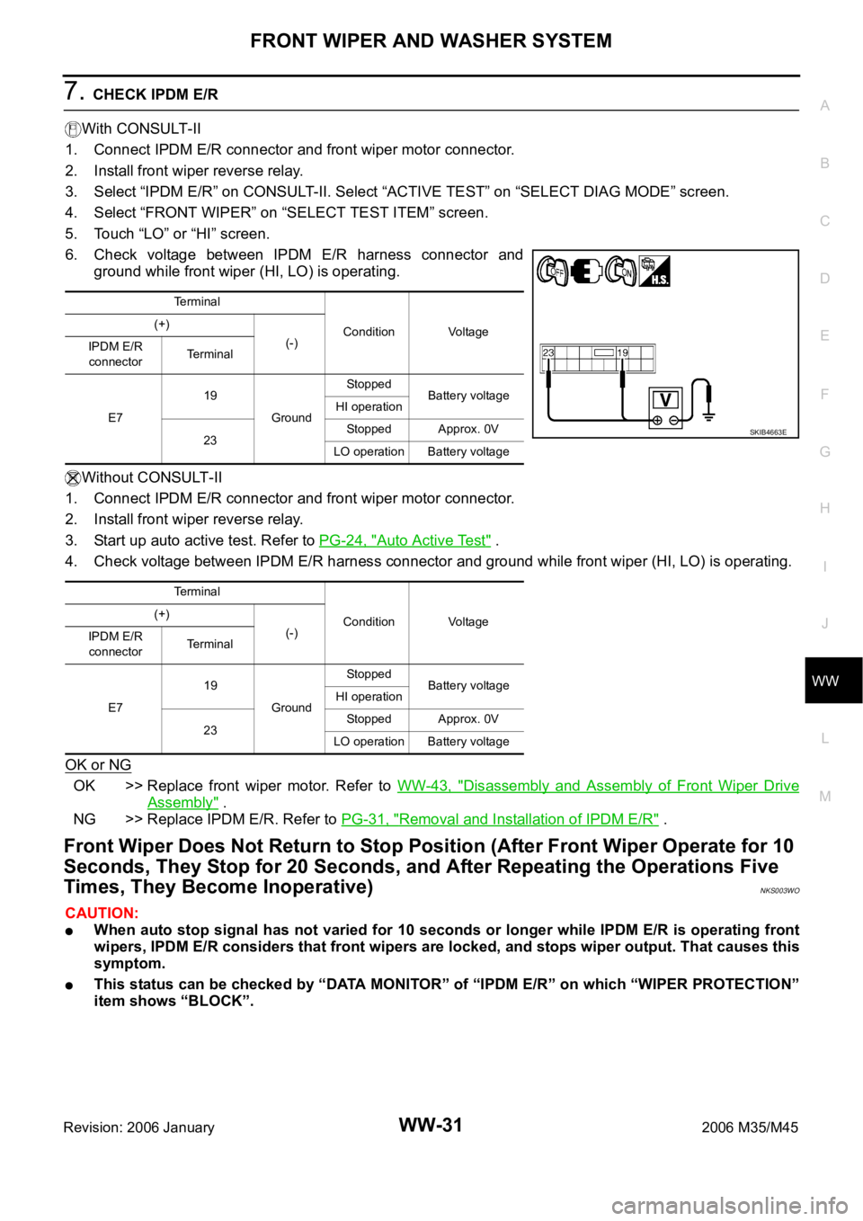
7. CHECK IPDM E/R
With CONSULT-II
1. Connect IPDM E/R connector and front wiper motor connector.
2. Install front wiper reverse relay.
3. Select “IPDM E/R” on CONSULT-II. Select “ACTIVE TEST” on “SELECT DIAG MODE” screen.
4. Select “FRONT WIPER” on “SELECT TEST ITEM” screen.
5. Touch “LO” or “HI” screen.
6. Check voltage between IPDM E/R harness connector and
ground while front wiper (HI, LO) is operating.
Without CONSULT-II
1. Connect IPDM E/R connector and front wiper motor connector.
2. Install front wiper reverse relay.
3. Start up auto active test. Refer to PG-24, "
Auto Active Test" .
4. Check voltage between IPDM E/R harness connector and ground while front wiper (HI, LO) is operating.
OK or NG
OK >> Replace front wiper motor. Refer to WW-43, "Disassembly and Assembly of Front Wiper Drive
Assembly" .
NG >> Replace IPDM E/R. Refer to PG-31, "
Removal and Installation of IPDM E/R" .
Front Wiper Does Not Return to Stop Position (After Front Wiper Operate for 10
Seconds, They Stop for 20 Seconds, and After Repeating the Operations Five
Times, They Become Inoperative)
NKS003WO
CAUTION:
When auto stop signal has not varied for 10 seconds or longer while IPDM E/R is operating front
wipers, IPDM E/R considers that front wipers are locked, and stops wiper output. That causes this
symptom.
This status can be checked by “DATA MONITOR” of “IPDM E/R” on which “WIPER PROTECTION”
item shows “BLOCK”.
Terminal
Condition Voltage (+)
(-)
IPDM E/R
connectorTerminal
E719
GroundStopped
Battery voltage
HI operation
23Stopped Approx. 0V
LO operation Battery voltage
Terminal
Condition Voltage (+)
(-)
IPDM E/R
connectorTerminal
E719
GroundStopped
Battery voltage
HI operation
23Stopped Approx. 0V
LO operation Battery voltage
SKIB4663E