2006 INFINITI M35 stall
[x] Cancel search: stallPage 5188 of 5621
SQUEAK AND RATTLE TROUBLE DIAGNOSES
SE-7
C
D
E
F
G
H
J
K
L
MA
B
SE
Revision: 2006 January2006 M35/M45
INSULATOR (Light foam block)
80845-71L00: 30 mm (1.18 in) thick, 30
50 mm (1.181.97 in)
FELT CLOTHTAPE
Used to insulate where movement does not occur. Ideal for instrument panel applications.
68370-4B000: 15
25 mm (0.590.98 in) pad/68239-13E00: 5 mm (0.20 in) wide tape roll
The following materials, not found in the kit, can also be used to repair squeaks and rattles.
UHMW (TEFLON) TAPE
Insulates where slight movement is present. Ideal for instrument panel applications.
SILICONE GREASE
Used in place of UHMW tape that will be visible or not fit. Will only last a few months.
SILICONE SPRAY
Use when grease cannot be applied.
DUCT TAPE
Use to eliminate movement.
CONFIRM THE REPAIR
Confirm that the cause of a noise is repaired by test driving the vehicle. Operate the vehicle under the same
conditions as when the noise originally occurred. Refer to the notes on the Diagnostic Worksheet.
Generic Squeak and Rattle TroubleshootingNIS0025O
Refer to Table of Contents for specific component removal and installation information.
INSTRUMENT PANEL
Most incidents are caused by contact and movement between:
1. The cluster lid A and instrument panel
2. Acrylic lens and combination meter housing
3. Instrument panel to front pillar garnish
4. Instrument panel to windshield
5. Instrument panel mounting pins
6. Wiring harnesses behind the combination meter
7. A/C defroster duct and duct joint
These incidents can usually be located by tapping or moving the components to duplicate the noise or by
pressing on the components while driving to stop the noise. Most of these incidents can be repaired by apply-
ing felt cloth tape or silicon spray (in hard to reach areas). Urethane pads can be used to insulate wiring har-
ness.
CAUTION:
Do not use silicone spray to isolate a squeak or rattle. If you saturate the area with silicone, you will
not be able to recheck the repair.
CENTER CONSOLE
Components to pay attention to include:
1. Shifter assembly cover to finisher
2. A/C control unit and cluster lid C
3. Wiring harnesses behind audio and A/C control unit
The instrument panel repair and isolation procedures also apply to the center console.
DOORS
Pay attention to the:
1. Finisher and inner panel making a slapping noise
2. Inside handle escutcheon to door finisher
3. Wiring harnesses tapping
4. Door striker out of alignment causing a popping noise on starts and stops
Tapping or moving the components or pressing on them while driving to duplicate the conditions can isolate
many of these incidents. You can usually insulate the areas with felt cloth tape or insulator foam blocks from
the Nissan Squeak and Rattle Kit (J-43980) to repair the noise.
Page 5222 of 5621
AUTOMATIC DRIVE POSITIONER
SE-41
C
D
E
F
G
H
J
K
L
MA
B
SE
Revision: 2006 January2006 M35/M45
CAN Communication Inspection Using CONSULT-II (Self-Diagnosis)NIS00263
1. SELF-DIAGNOSTIC RESULT CHECK
CAUTION:
If CONSULT-II is used with no connection of CONSULT-II CONVERTER, malfunctions might be
detected in self-diagnosis depending on control unit which carry out CAN communication.
1. Connect to CONSULT-II, and select “AUTO DRIVE POS.” on the “SELECT DIAG SYSTEM” screen.
2. Select “SELF-DIAG RESULTS” on “SELECT DIAG MODE” screen.
3. Check display content in self-diagnostic results.
Contents displayed
No malfunction>>Inspection End.
Malfunction in CAN communication system>>After printing the monitor items, go to “CAN System”. Refer to
LAN-7, "
Precautions When Using CONSULT-II" .
BCM Power Supply and Ground Circuit CheckNIS00264
1. CHECK FUSE
Check if any of the following fuses in the BCM are blown.
NOTE:
Refer to SE-11, "
Component Parts And Harness Connector Location" .
OK or NG
OK >> GO TO 2.
NG >> If fuse is blown, be sure to eliminate cause of malfunction before installing new fuse. Refer to PG-
3, "POWER SUPPLY ROUTING CIRCUIT" .
CONSULT-II display code Diagnosis item
U1000INITIAL DIAG
TRANSMIT DIAG
BCM/SEC
METER/M&A
TCM
Unit Power source Fuse No.
BCMBattery power supplyF (50A)
Battery power supply 21 (10A)
Ignition switch ON or STRAT signal 1 (15A)
Ignition switch ACC or ON signal 6 (10A)
Page 5225 of 5621
SE-44
AUTOMATIC DRIVE POSITIONER
Revision: 2006 January2006 M35/M45
Sliding Motor Circuit CheckNIS00267
1. CHECK SEAT SLIDING MECHANISM
Check the following.
Operation malfunction caused by sliding rail deformation, pinched harness or other foreign materials
Operation malfunction caused by foreign materials adhered to the sliding motor or sliding rail connector
rod
Operation malfunction and interference with other parts by poor installation
OK or NG
OK >> GO TO 2.
NG >> Repair or replace the malfunctioning part and check again.
2. CHECK FUNCTION
With CONSULT-II
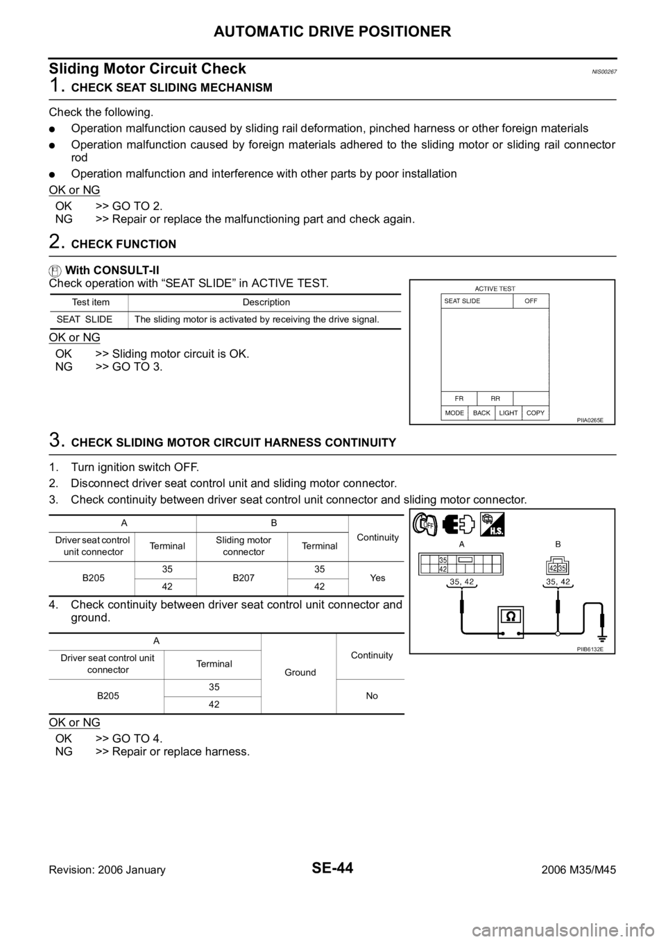
Check operation with “SEAT SLIDE” in ACTIVE TEST.
OK or NG
OK >> Sliding motor circuit is OK.
NG >> GO TO 3.
3. CHECK SLIDING MOTOR CIRCUIT HARNESS CONTINUITY
1. Turn ignition switch OFF.
2. Disconnect driver seat control unit and sliding motor connector.
3. Check continuity between driver seat control unit connector and sliding motor connector.
4. Check continuity between driver seat control unit connector and
ground.
OK or NG
OK >> GO TO 4.
NG >> Repair or replace harness.
Test item Description
SEAT SLIDE The sliding motor is activated by receiving the drive signal.
PIIA0265E
AB
Continuity
Driver seat control
unit connectorTe r m i n a lSliding motor
connectorTerminal
B20535
B20735
Ye s
42 42
A
GroundContinuity
Driver seat control unit
connectorTerminal
B20535
No
42
PIIB6132E
Page 5226 of 5621
AUTOMATIC DRIVE POSITIONER
SE-45
C
D
E
F
G
H
J
K
L
MA
B
SE
Revision: 2006 January2006 M35/M45
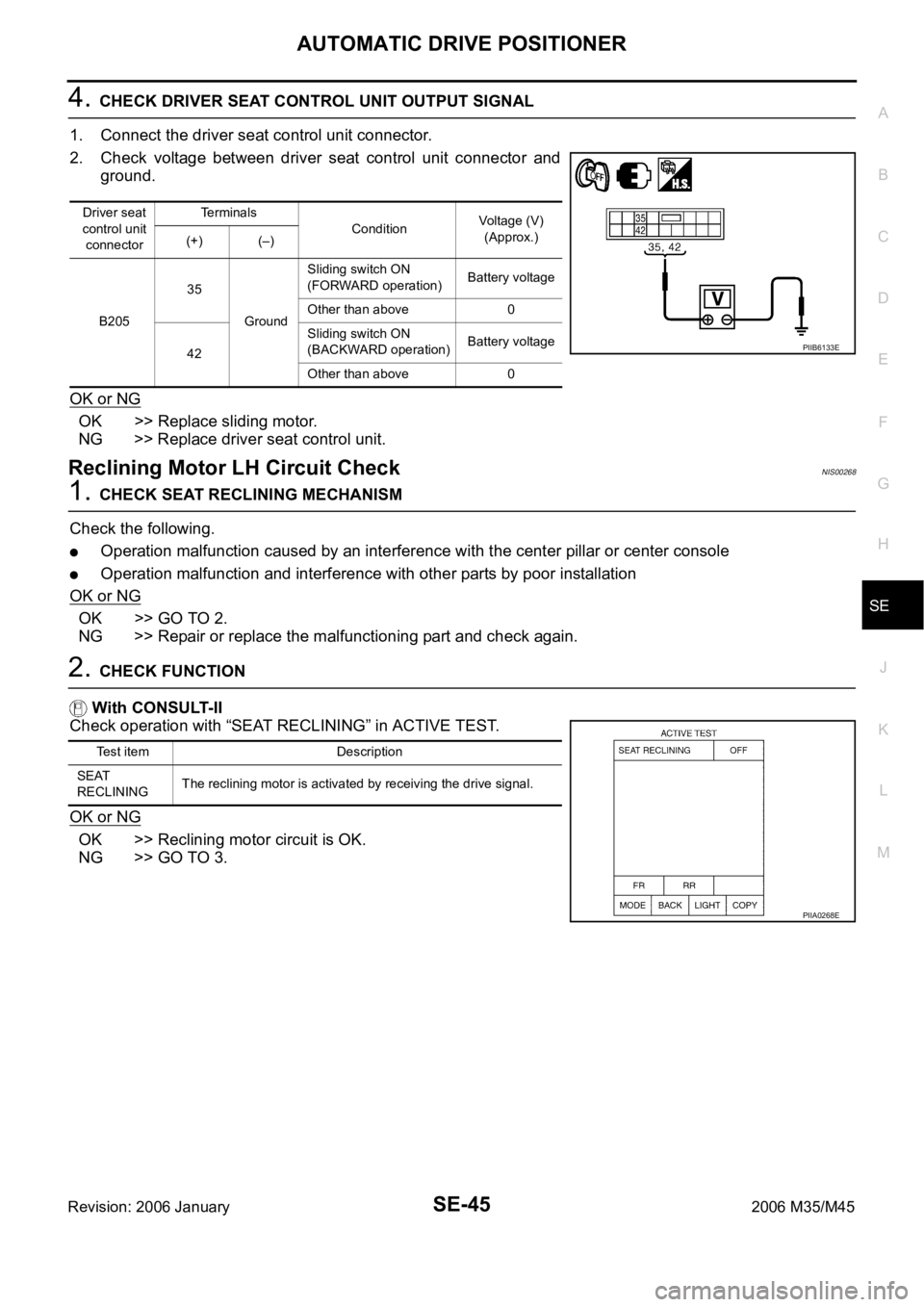
4. CHECK DRIVER SEAT CONTROL UNIT OUTPUT SIGNAL
1. Connect the driver seat control unit connector.
2. Check voltage between driver seat control unit connector and
ground.
OK or NG
OK >> Replace sliding motor.
NG >> Replace driver seat control unit.
Reclining Motor LH Circuit CheckNIS00268
1. CHECK SEAT RECLINING MECHANISM
Check the following.
Operation malfunction caused by an interference with the center pillar or center console
Operation malfunction and interference with other parts by poor installation
OK or NG
OK >> GO TO 2.
NG >> Repair or replace the malfunctioning part and check again.
2. CHECK FUNCTION
With CONSULT-II
Check operation with “SEAT RECLINING” in ACTIVE TEST.
OK or NG
OK >> Reclining motor circuit is OK.
NG >> GO TO 3.
Driver seat
control unit
connectorTerminals
ConditionVoltage (V)
(Approx.)
(+) (–)
B20535
GroundSliding switch ON
(FORWARD operation)Battery voltage
Other than above 0
42Sliding switch ON
(BACKWARD operation)Battery voltage
Other than above 0
PIIB6133E
Test item Description
SEAT
RECLININGThe reclining motor is activated by receiving the drive signal.
PIIA0268E
Page 5227 of 5621
SE-46
AUTOMATIC DRIVE POSITIONER
Revision: 2006 January2006 M35/M45
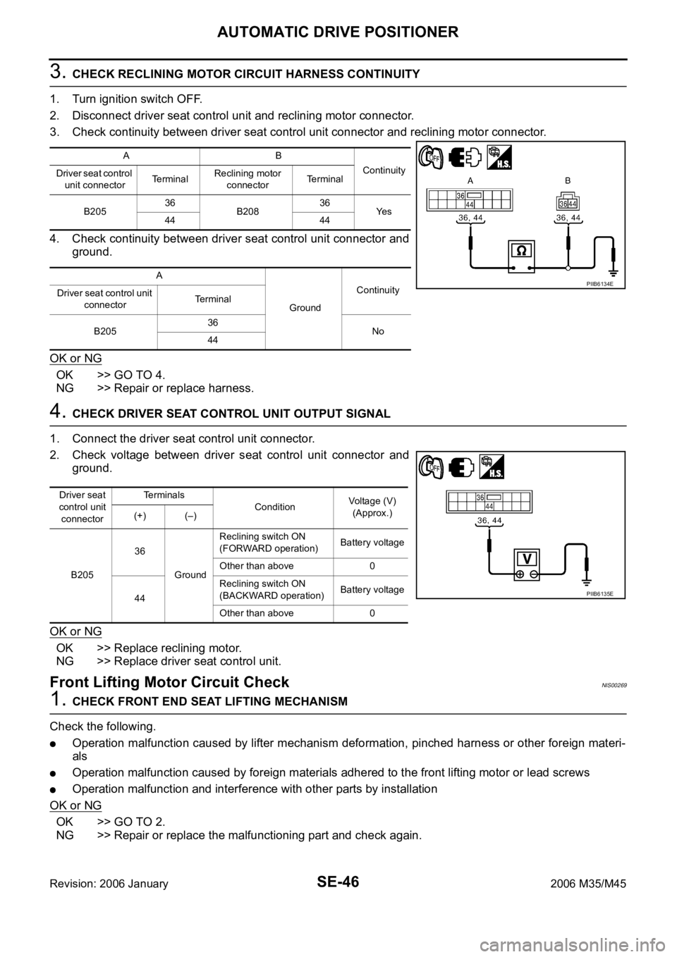
3. CHECK RECLINING MOTOR CIRCUIT HARNESS CONTINUITY
1. Turn ignition switch OFF.
2. Disconnect driver seat control unit and reclining motor connector.
3. Check continuity between driver seat control unit connector and reclining motor connector.
4. Check continuity between driver seat control unit connector and
ground.
OK or NG
OK >> GO TO 4.
NG >> Repair or replace harness.
4. CHECK DRIVER SEAT CONTROL UNIT OUTPUT SIGNAL
1. Connect the driver seat control unit connector.
2. Check voltage between driver seat control unit connector and
ground.
OK or NG
OK >> Replace reclining motor.
NG >> Replace driver seat control unit.
Front Lifting Motor Circuit CheckNIS00269
1. CHECK FRONT END SEAT LIFTING MECHANISM
Check the following.
Operation malfunction caused by lifter mechanism deformation, pinched harness or other foreign materi-
als
Operation malfunction caused by foreign materials adhered to the front lifting motor or lead screws
Operation malfunction and interference with other parts by installation
OK or NG
OK >> GO TO 2.
NG >> Repair or replace the malfunctioning part and check again.
AB
Continuity
Driver seat control
unit connectorTe r m i n a lReclining motor
connectorTerminal
B20536
B20836
Ye s
44 44
A
GroundContinuity
Driver seat control unit
connectorTerminal
B20536
No
44
PIIB6134E
Driver seat
control unit
connectorTerminals
ConditionVoltage (V)
(Approx.)
(+) (–)
B20536
GroundReclining switch ON
(FORWARD operation)Battery voltage
Other than above 0
44Reclining switch ON
(BACKWARD operation)Battery voltage
Other than above 0
PIIB6135E
Page 5229 of 5621
SE-48
AUTOMATIC DRIVE POSITIONER
Revision: 2006 January2006 M35/M45
Rear Lifting Motor Circuit CheckNIS0026A
1. CHECK REAR SEAT LIFTING MECHANISM
Check the following.
Operation malfunction caused by lifter mechanism deformation or pinched harness or other foreign mate-
rials
Operation malfunction caused by foreign materials adhered to the rear lifting motor or lead screws
Operation malfunction and interference with other parts by poor installation
OK or NG
OK >> GO TO 2.
NG >> Repair or replace the malfunctioning part and check again.
2. CHECK FUNCTION
With CONSULT-II
Check operation with “SEAT LIFTER RR” in ACTIVE TEST.
OK or NG
OK >> Rear lifting motor circuit is OK.
NG >> GO TO 3.
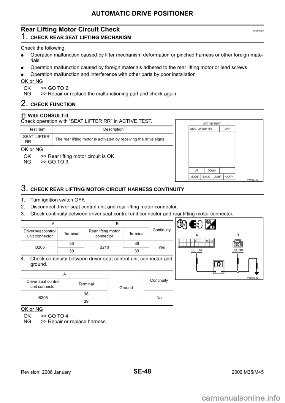
3. CHECK REAR LIFTING MOTOR CIRCUIT HARNESS CONTINUITY
1. Turn ignition switch OFF.
2. Disconnect driver seat control unit and rear lifting motor connector.
3. Check continuity between driver seat control unit connector and rear lifting motor connector.
4. Check continuity between driver seat control unit connector and
ground.
OK or NG
OK >> GO TO 4.
NG >> Repair or replace harness.
Test item Description
SEAT LIFTER
RRThe rear lifting motor is activated by receiving the drive signal.
PIIA0274E
AB
Continuity
Driver seat control
unit connectorTe r m i n a lRear lifting motor
connectorTerminal
B20538
B21038
Ye s
39 39
A
GroundContinuity
Driver seat control
unit connectorTerminal
B20538
No
39
PIIB6138E
Page 5230 of 5621

AUTOMATIC DRIVE POSITIONER
SE-49
C
D
E
F
G
H
J
K
L
MA
B
SE
Revision: 2006 January2006 M35/M45
4. CHECK DRIVER SEAT CONTROL UNIT OUTPUT SIGNAL
1. Connect the driver seat control unit connector.
2. Check voltage between driver seat control unit connector and ground.
OK or NG
OK >> Replace rear lifting motor.
NG >> Replace driver seat control unit.
Telescopic Motor Circuit CheckNIS0026B
1. CHECK STEERING WHEEL TELESCOPIC MECHANISM
Check following.
Operation malfunction caused by steering wheel telescopic mechanism deformation or pinched harness
or other foreign materials
Operation malfunction and interference with other parts by poor installation
OK or NG
OK >> GO TO 2.
NG >> Repair the malfunctioning part and check again.
2. CHECK FUNCTION
With CONSULT-II
Check operation with “TELESCO MOTOR” in ACTIVE TEST.
OK or NG
OK >> Steering telescopic motor circuit is OK.
NG >> GO TO 3.
Driver
seat con-
trol unit
connectorTe r m i n a l s
ConditionVoltage (V)
(Approx.)
(+) (–)
B20538
GroundLifting switch (rear) ON
(UP operation)Battery voltage
Other than above 0
39Lifting switch (rear) ON
(DOWN operation)Battery voltage
Other than above 0
PIIB6139E
Test item Description
TELESCO
MOTORThe telescopic motor is activated by receiving the drive signal.
PIIA0277E
Page 5231 of 5621
SE-50
AUTOMATIC DRIVE POSITIONER
Revision: 2006 January2006 M35/M45
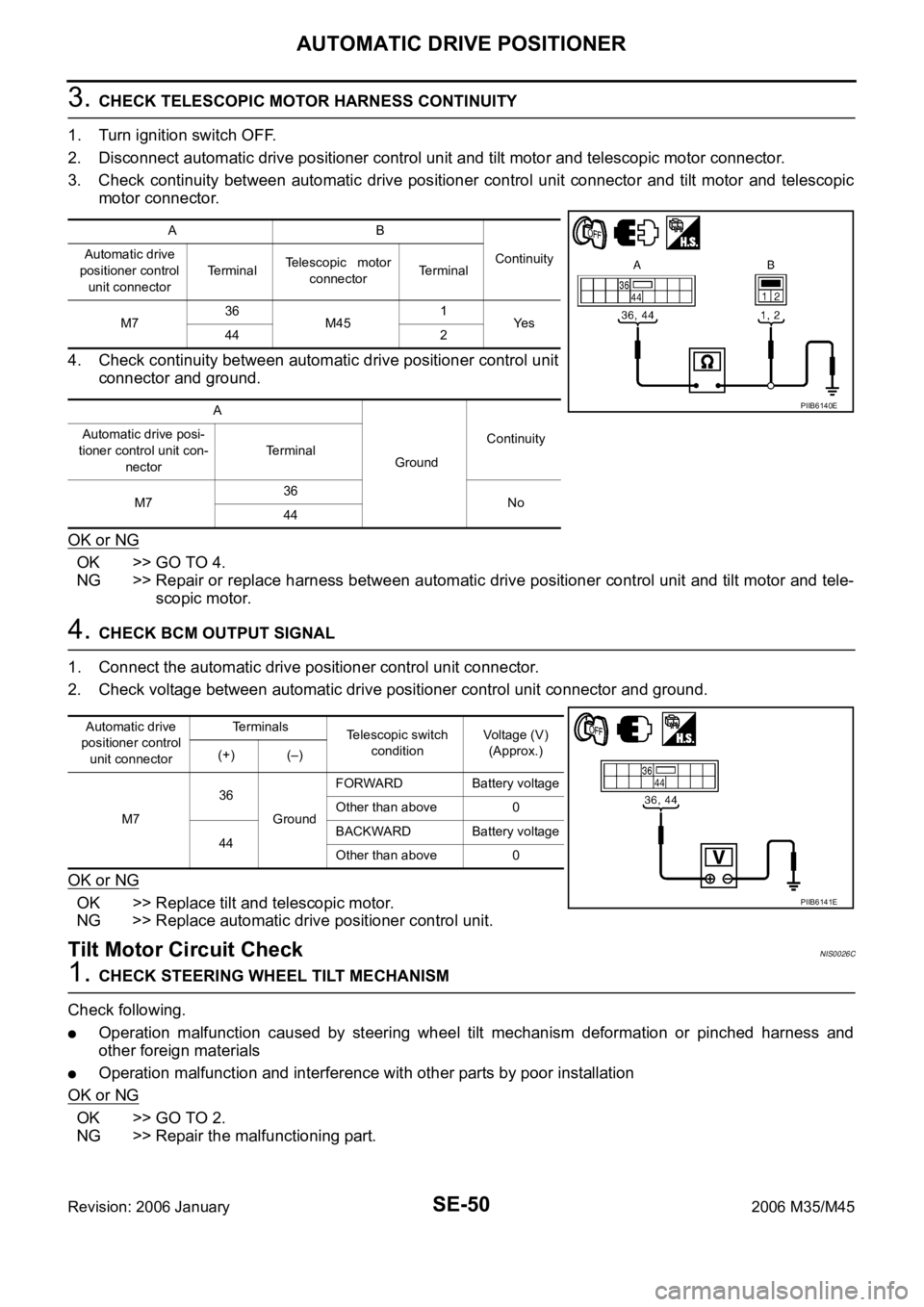
3. CHECK TELESCOPIC MOTOR HARNESS CONTINUITY
1. Turn ignition switch OFF.
2. Disconnect automatic drive positioner control unit and tilt motor and telescopic motor connector.
3. Check continuity between automatic drive positioner control unit connector and tilt motor and telescopic
motor connector.
4. Check continuity between automatic drive positioner control unit
connector and ground.
OK or NG
OK >> GO TO 4.
NG >> Repair or replace harness between automatic drive positioner control unit and tilt motor and tele-
scopic motor.
4. CHECK BCM OUTPUT SIGNAL
1. Connect the automatic drive positioner control unit connector.
2. Check voltage between automatic drive positioner control unit connector and ground.
OK or NG
OK >> Replace tilt and telescopic motor.
NG >> Replace automatic drive positioner control unit.
Tilt Motor Circuit CheckNIS0026C
1. CHECK STEERING WHEEL TILT MECHANISM
Check following.
Operation malfunction caused by steering wheel tilt mechanism deformation or pinched harness and
other foreign materials
Operation malfunction and interference with other parts by poor installation
OK or NG
OK >> GO TO 2.
NG >> Repair the malfunctioning part.
AB
Continuity Automatic drive
positioner control
unit connectorTe r m i n a lTelescopic motor
connectorTerminal
M736
M451
Ye s
44 2
A
GroundContinuity Automatic drive posi-
tioner control unit con-
nectorTerminal
M736
No
44
PIIB6140E
Automatic drive
positioner control
unit connectorTerminals
Telescopic switch
conditionVoltage (V)
(Approx.)
(+) (–)
M736
GroundFORWARD Battery voltage
Other than above 0
44BACKWARD Battery voltage
Other than above 0
PIIB6141E