2006 INFINITI M35 stall
[x] Cancel search: stallPage 5136 of 5621
TOP TETHER STRAP CHILD RESTRAINT
SB-37
C
D
E
F
G
I
J
K
L
MA
B
SB
Revision: 2006 January2006 M35/M45
TOP TETHER STRAP CHILD RESTRAINTPFP:88000
Removal and InstallationNHS0008N
CAUTION:
Replace anchor bolts if they are deformed or worn out.
REMOVAL
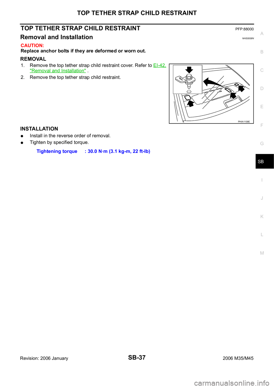
1. Remove the top tether strap child restraint cover. Refer to EI-42,
"Removal and Installation" .
2. Remove the top tether strap child restraint.
INSTALLATION
Install in the reverse order of removal.
Tighten by specified torque.
PHIA1109E
Tightening torque : 30.0 Nꞏm (3.1 kg-m, 22 ft-lb)
Page 5138 of 5621
SC-1
STARTING & CHARGING SYSTEM
K ELECTRICAL
CONTENTS
C
D
E
F
G
H
I
J
L
M
SECTION SC
A
B
SC
Revision: 2006 January2006 M35/M45
STARTING & CHARGING SYSTEM
PRECAUTIONS .......................................................... 2
Precautions for Supplemental Restraint System
(SRS) “AIR BAG” and “SEAT BELT PRE-TEN-
SIONER” .................................................................. 2
Precautions for Power Generation Voltage Variable
Control System ......................................................... 2
PREPARATION ........................................................... 3
Special Service Tools ............................................... 3
Commercial Service Tools ........................................ 3
BATTERY .................................................................... 4
How to Handle Battery ............................................. 4
METHODS OF PREVENTING OVER-DIS-
CHARGE ............................................................... 4
CHECKING ELECTROLYTE LEVEL .................... 5
SPECIFIC GRAVITY CHECK ............................... 5
CHARGING THE BATTERY ................................. 6
Trouble Diagnosis with Battery/Starting/Charging
System Tester (Battery) ............................................ 7
DIAGNOSTIC RESULT ITEM CHART .................. 8
Removal and Installation .......................................... 9
REMOVAL ........................................................
..... 9
INSTALLATION ..................................................... 9
STARTING SYSTEM ................................................ 10
System Description ................................................ 10
Wiring Diagram — START — .................................. 11
VQ35DE ENGINE MODELS ................................ 11
VK45DE ENGINE MODELS ............................... 12
Trouble Diagnosis with Battery/Starting/Charging
System Tester (Starting) ......................................... 13
DIAGNOSTIC RESULT ITEM CHART ................ 13
WORK FLOW ...................................................... 14
DIAGNOSTIC PROCEDURE 1 ........................... 15
DIAGNOSTIC PROCEDURE 2 ........................... 16
MINIMUM SPECIFICATION OF CRANKING
VOLTAGE REFERENCING COOLANT TEM-
PERATURE ......................................................... 16
Removal and Installation ........................................ 17
VQ35DE ENGINE MODELS (2WD) .................... 17VQ35DE ENGINE MODELS (AWD) .................... 18
VK45DE ENGINE MODELS ................................ 19
Disassembly and Assembly .................................... 20
VQ35DE ENGINE MODELS (2WD) .................... 20
VQ35DE ENGINE MODELS (AWD) .................... 21
VK45DE ENGINE MODELS ................................ 22
INSPECTION AFTER DISASSEMBLY ................ 22
CHARGING SYSTEM ............................................... 23
System Description ................................................. 23
DESCRIPTION .................................................... 23
MALFUNCTION INDICATOR .............................. 23
POWER GENERATION VOLTAGE VARIABLE
CONTROL SYSTEM ........................................... 24
Wiring Diagram — CHARGE — ............................. 25
VQ35DE ENGINE MODELS (2WD) .................... 25
VQ35DE ENGINE MODELS (AWD) .................... 26
VK45DE ENGINE MODELS .............................
... 27
Trouble Diagnoses with Battery/Starting/Charging
System Tester (Charging) ....................................... 28
DIAGNOSTIC RESULT ITEM CHART ................ 30
WORK FLOW ...................................................... 31
PRELIMINARY INSPECTION ............................. 32
DIAGNOSTIC PROCEDURE 1 ........................... 32
DIAGNOSTIC PROCEDURE 2 ........................... 33
DIAGNOSTIC PROCEDURE 3 ........................... 33
DIAGNOSTIC PROCEDURE 4 ........................... 34
Power Generation Voltage Variable Control System
Operation Inspection .............................................. 35
Removal and Installation ........................................ 37
VQ35DE ENGINE MODELS ............................... 37
VK45DE ENGINE MODELS ................................ 39
Disassembly and Assembly .................................... 41
VQ35DE ENGINE MODELS ............................... 41
VK45DE ENGINE MODELS ................................ 42
SERVICE DATA AND SPECIFICATIONS (SDS) ...... 43
Battery .................................................................... 43
Starter ..................................................................... 43
Alternator ................................................................ 43
Page 5139 of 5621
SC-2
PRECAUTIONS
Revision: 2006 January2006 M35/M45
PRECAUTIONS PFP:00011
Precautions for Supplemental Restraint System (SRS) “AIR BAG” and “SEAT
BELT PRE-TENSIONER”
NKS003NB
The Supplemental Restraint System such as “AIR BAG” and “SEAT BELT PRE-TENSIONER”, used along
with a front seat belt, helps to reduce the risk or severity of injury to the driver and front passenger for certain
types of collision. This system includes seat belt switch inputs and dual stage front air bag modules. The SRS
system uses the seat belt switches to determine the front air bag deployment, and may only deploy one front
air bag, depending on the severity of a collision and whether the front occupants are belted or unbelted.
Information necessary to service the system safely is included in the SRS and SB section of this Service Man-
ual.
WAR NING :
To avoid rendering the SRS inoperative, which could increase the risk of personal injury or death
in the event of a collision which would result in air bag inflation, all maintenance must be per-
formed by an authorized NISSAN/INFINITI dealer.
Improper maintenance, including incorrect removal and installation of the SRS, can lead to per-
sonal injury caused by unintentional activation of the system. For removal of Spiral Cable and Air
Bag Module, see the SRS section.
Do not use electrical test equipment on any circuit related to the SRS unless instructed to in this
Service Manual. SRS wiring harnesses can be identified by yellow and/or orange harnesses or
harness connectors.
Precautions for Power Generation Voltage Variable Control SystemNKS003NC
CAUTION:
For this model, the battery current sensor that is installed to the battery cable at the negative terminal
measures the charging/discharging current of the battery, and performs various controls. If the electri-
cal component or the ground wire is connected directly to the battery terminal, the current other than
that being measured with the battery current sensor is charging to or discharging from the battery.
This condition causes the malfunction of the control, and then the battery discharge may occur. Do
not connect the electrical component or the ground wire directly to the battery terminal.
Page 5145 of 5621
SC-8
BATTERY
Revision: 2006 January2006 M35/M45
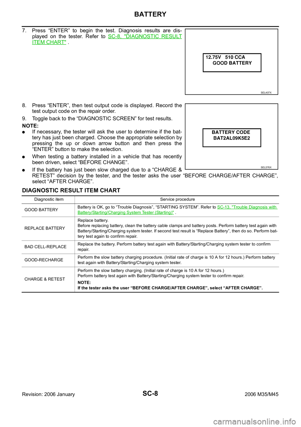
7. Press “ENTER” to begin the test. Diagnosis results are dis-
played on the tester. Refer to SC-8, "
DIAGNOSTIC RESULT
ITEM CHART" .
8. Press “ENTER”, then test output code is displayed. Record the
test output code on the repair order.
9. Toggle back to the “DIAGNOSTIC SCREEN” for test results.
NOTE:
If necessary, the tester will ask the user to determine if the bat-
tery has just been charged. Choose the appropriate selection by
pressing the up or down arrow button and then press the
“ENTER” button to make the selection.
When testing a battery installed in a vehicle that has recently
been driven, select “BEFORE CHANGE”.
If the battery has just been slow charged due to a “CHARGE &
RETEST” decision by the tester, and the tester asks the user “BEFORE CHARGE/AFTER CHARGE”,
select “AFTER CHARGE”.
DIAGNOSTIC RESULT ITEM CHART
SEL407X
SEL576X
Diagnostic item Service procedure
GOOD BATTERYBattery is OK, go to “Trouble Diagnosis”, “STARTING SYSTEM”. Refer to SC-13, "
Trouble Diagnosis with
Battery/Starting/Charging System Tester (Starting)" .
REPLACE BATTERYReplace battery.
Before replacing battery, clean the battery cable clamps and battery posts. Perform battery test again with
Battery/Starting/Charging system tester. If second test result is “Replace Battery”, then do so. Perform bat-
tery test again to confirm repair.
BAD CELL-REPLACEReplace the battery. Perform battery test again with Battery/Starting/Charging system tester to confirm
repair.
GOOD-RECHARGEPerform the slow battery charging procedure. (Initial rate of charge is 10 A for 12 hours.) Perform battery
test again with Battery/Starting/Charging system tester.
CHARGE & RETESTPerform the slow battery charging. (Initial rate of charge is 10 A for 12 hours.)
Perform battery test again with Battery/Starting/Charging system tester to confirm repair.
NOTE:
If the tester asks the user “BEFORE CHARGE/AFTER CHARGE”, select “AFTER CHARGE”.
Page 5146 of 5621
BATTERY
SC-9
C
D
E
F
G
H
I
J
L
MA
B
SC
Revision: 2006 January2006 M35/M45
Removal and Installation NKS003NH
REMOVAL
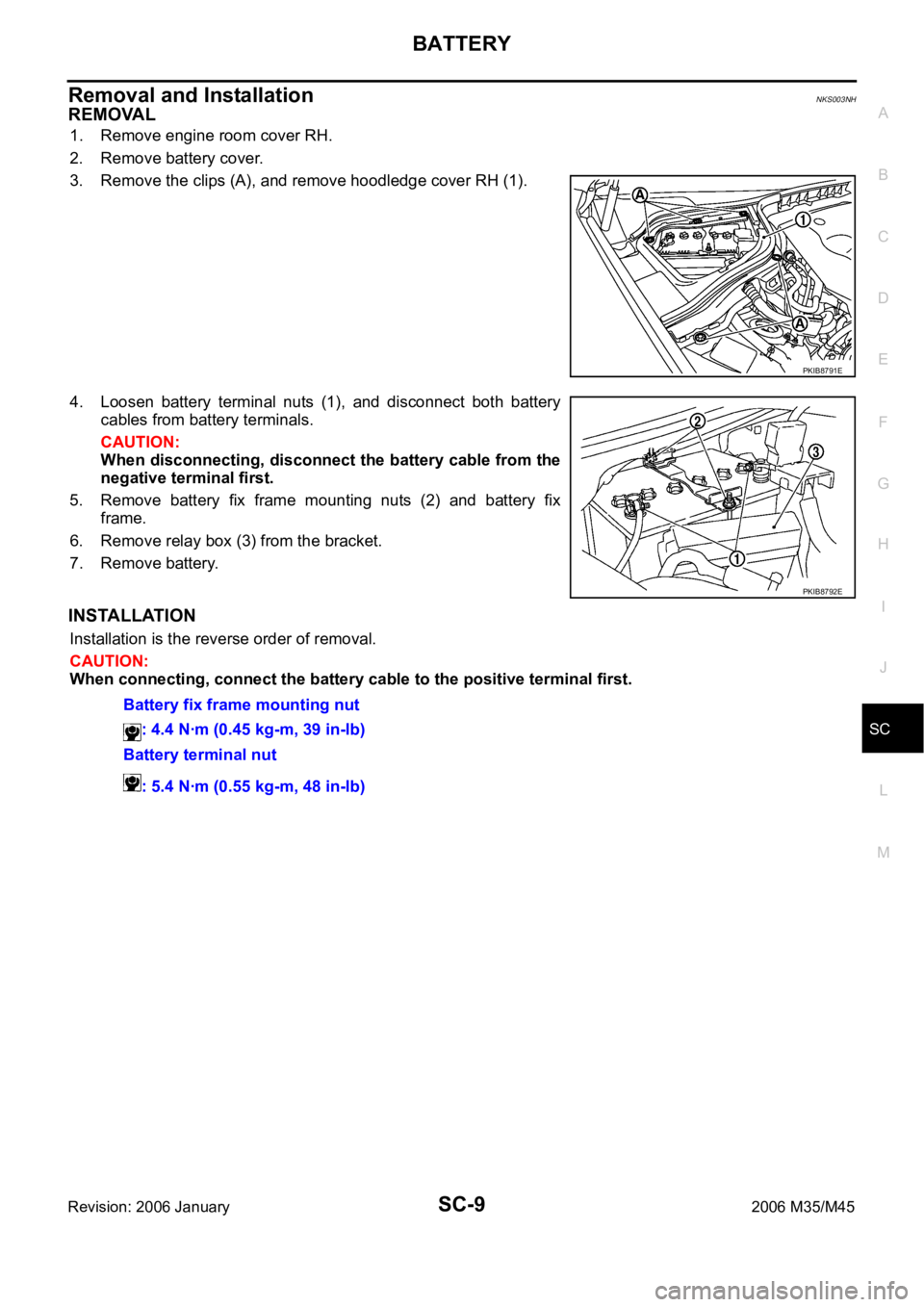
1. Remove engine room cover RH.
2. Remove battery cover.
3. Remove the clips (A), and remove hoodledge cover RH (1).
4. Loosen battery terminal nuts (1), and disconnect both battery
cables from battery terminals.
CAUTION:
When disconnecting, disconnect the battery cable from the
negative terminal first.
5. Remove battery fix frame mounting nuts (2) and battery fix
frame.
6. Remove relay box (3) from the bracket.
7. Remove battery.
INSTALLATION
Installation is the reverse order of removal.
CAUTION:
When connecting, connect the battery cable to the positive terminal first.
PKIB8791E
PKIB8792E
Battery fix frame mounting nut
: 4.4 Nꞏm (0.45 kg-m, 39 in-lb)
Battery terminal nut
: 5.4 Nꞏm (0.55 kg-m, 48 in-lb)
Page 5154 of 5621
STARTING SYSTEM
SC-17
C
D
E
F
G
H
I
J
L
MA
B
SC
Revision: 2006 January2006 M35/M45
Removal and Installation NKS003NL
VQ35DE ENGINE MODELS (2WD)
Removal
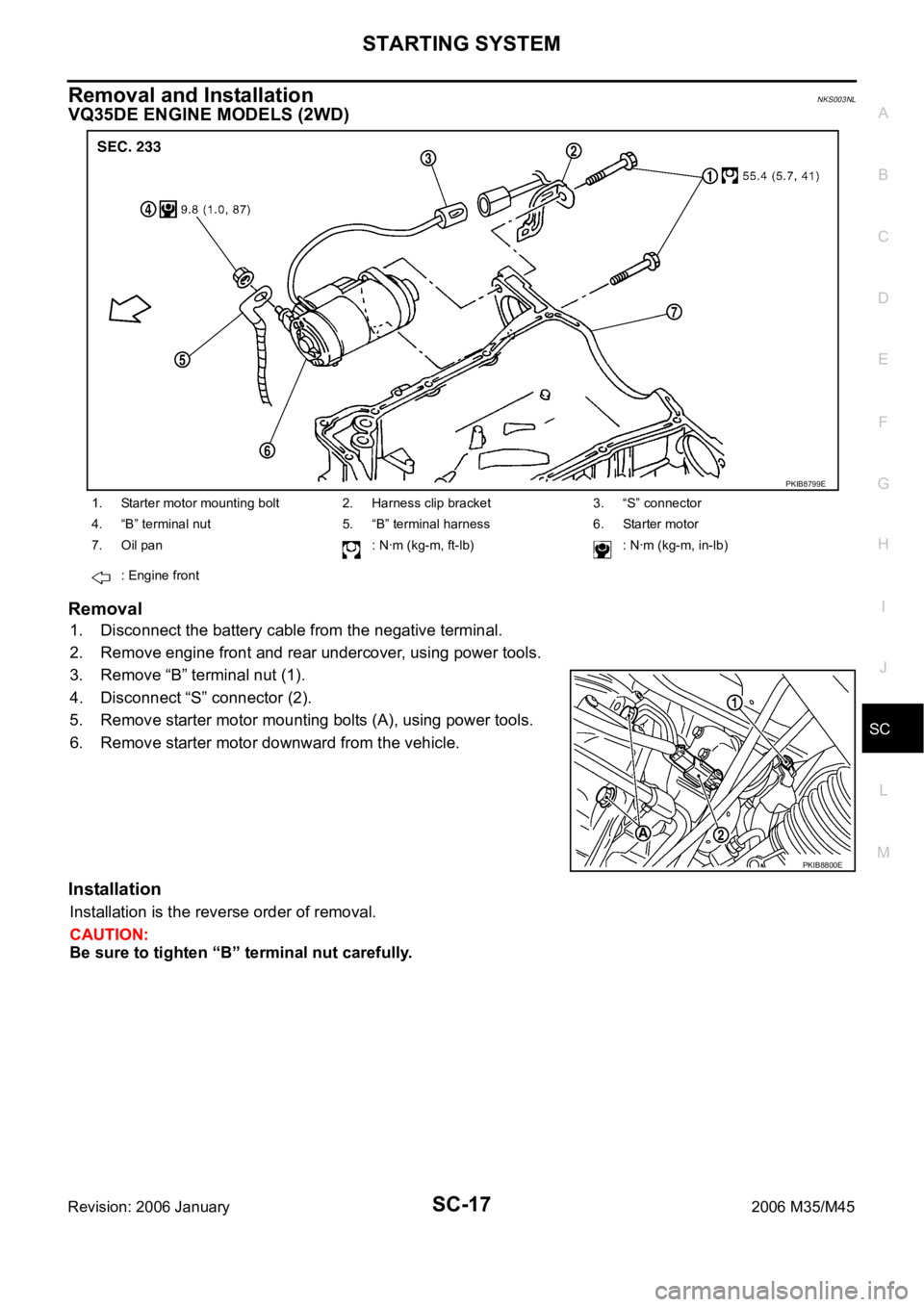
1. Disconnect the battery cable from the negative terminal.
2. Remove engine front and rear undercover, using power tools.
3. Remove “B” terminal nut (1).
4. Disconnect “S” connector (2).
5. Remove starter motor mounting bolts (A), using power tools.
6. Remove starter motor downward from the vehicle.
Installation
Installation is the reverse order of removal.
CAUTION:
Be sure to tighten “B” terminal nut carefully.
1. Starter motor mounting bolt 2. Harness clip bracket 3. “S” connector
4. “B” terminal nut 5. “B” terminal harness 6. Starter motor
7. Oil pan : Nꞏm (kg-m, ft-lb) : Nꞏm (kg-m, in-lb)
: Engine front
PKIB8799E
PKIB8800E
Page 5155 of 5621
SC-18
STARTING SYSTEM
Revision: 2006 January2006 M35/M45
VQ35DE ENGINE MODELS (AWD)
Removal
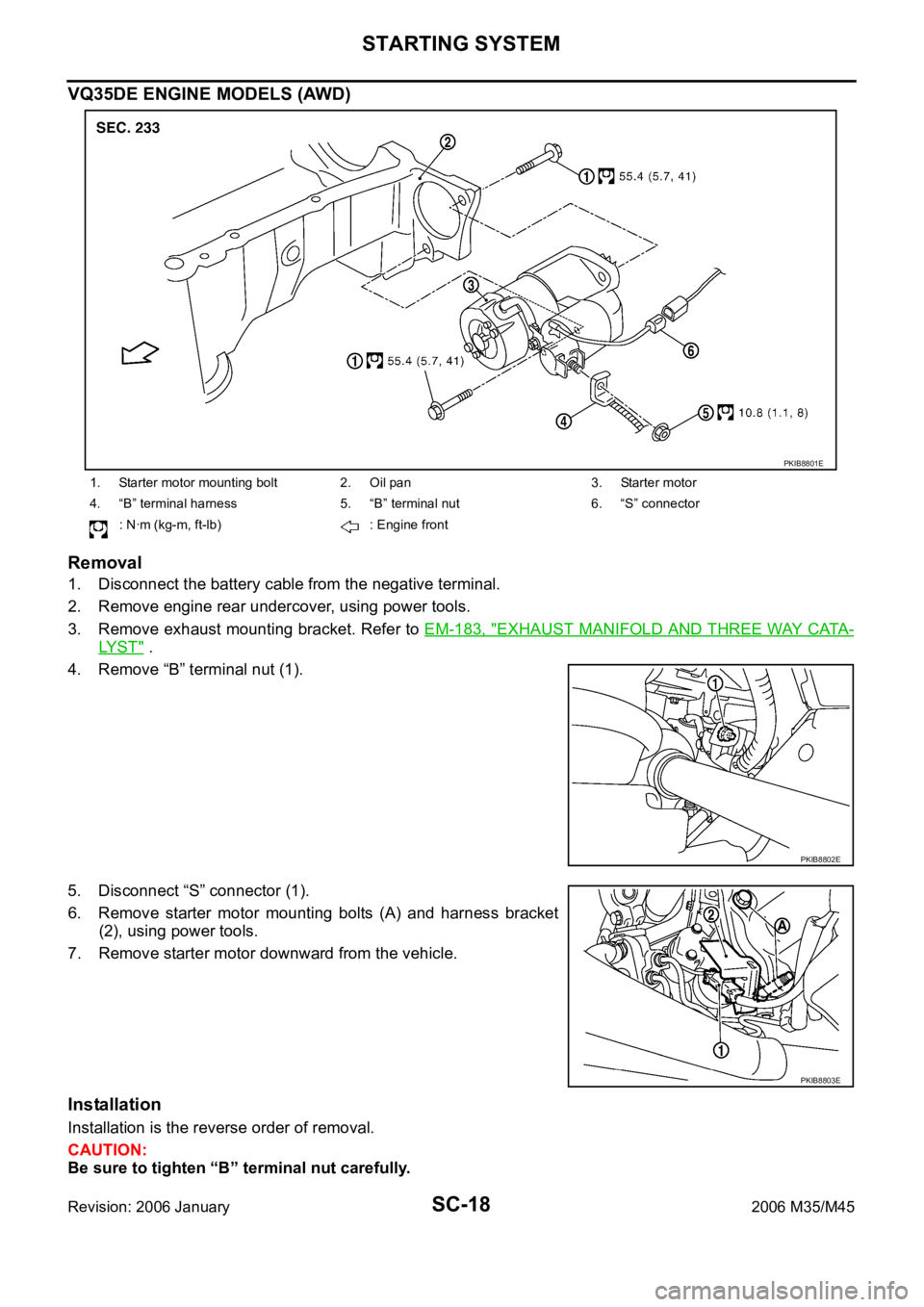
1. Disconnect the battery cable from the negative terminal.
2. Remove engine rear undercover, using power tools.
3. Remove exhaust mounting bracket. Refer to EM-183, "
EXHAUST MANIFOLD AND THREE WAY CATA-
LY S T" .
4. Remove “B” terminal nut (1).
5. Disconnect “S” connector (1).
6. Remove starter motor mounting bolts (A) and harness bracket
(2), using power tools.
7. Remove starter motor downward from the vehicle.
Installation
Installation is the reverse order of removal.
CAUTION:
Be sure to tighten “B” terminal nut carefully.
1. Starter motor mounting bolt 2. Oil pan 3. Starter motor
4. “B” terminal harness 5. “B” terminal nut 6. “S” connector
: Nꞏm (kg-m, ft-lb) : Engine front
PKIB8801E
PKIB8802E
PKIB8803E
Page 5156 of 5621
STARTING SYSTEM
SC-19
C
D
E
F
G
H
I
J
L
MA
B
SC
Revision: 2006 January2006 M35/M45
VK45DE ENGINE MODELS
Removal
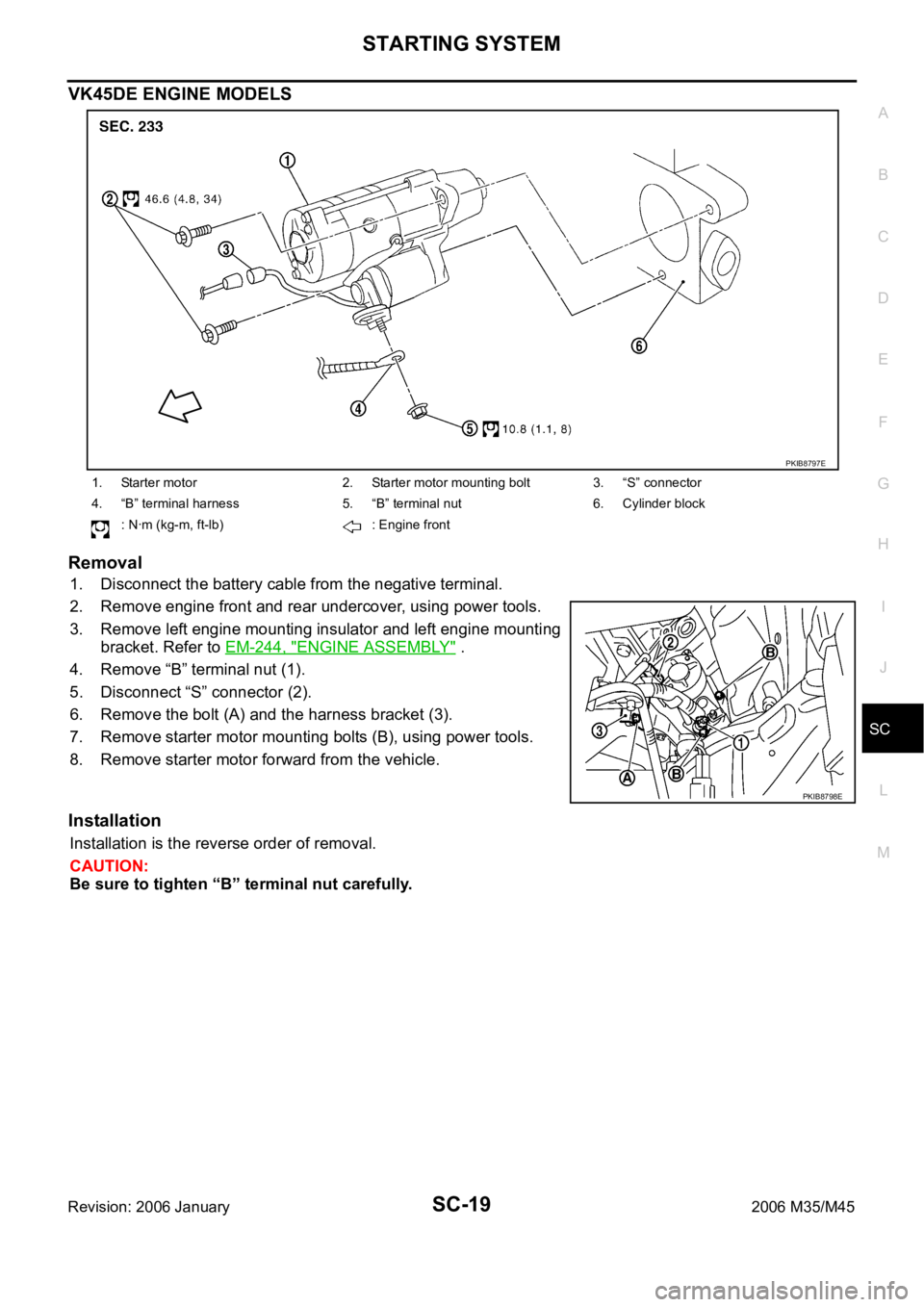
1. Disconnect the battery cable from the negative terminal.
2. Remove engine front and rear undercover, using power tools.
3. Remove left engine mounting insulator and left engine mounting
bracket. Refer to EM-244, "
ENGINE ASSEMBLY" .
4. Remove “B” terminal nut (1).
5. Disconnect “S” connector (2).
6. Remove the bolt (A) and the harness bracket (3).
7. Remove starter motor mounting bolts (B), using power tools.
8. Remove starter motor forward from the vehicle.
Installation
Installation is the reverse order of removal.
CAUTION:
Be sure to tighten “B” terminal nut carefully.
1. Starter motor 2. Starter motor mounting bolt 3. “S” connector
4. “B” terminal harness 5. “B” terminal nut 6. Cylinder block
: Nꞏm (kg-m, ft-lb) : Engine front
PKIB8797E
PKIB8798E