Page 5284 of 5621
POWER SEAT(REAR)
SE-103
C
D
E
F
G
H
J
K
L
MA
B
SE
Revision: 2006 January2006 M35/M45
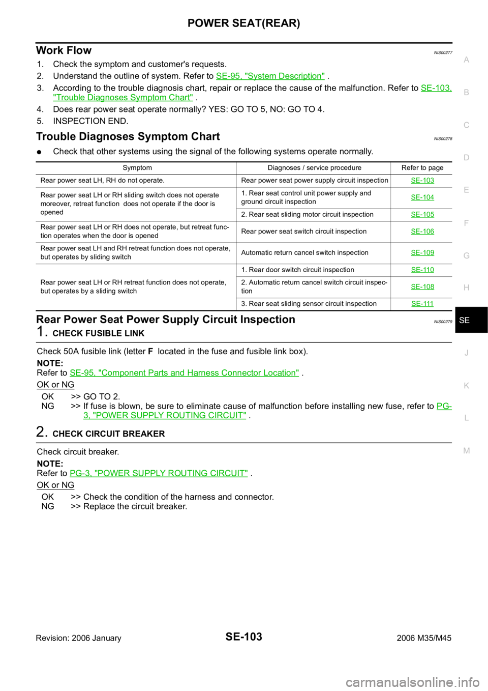
Work FlowNIS00277
1. Check the symptom and customer's requests.
2. Understand the outline of system. Refer to SE-95, "
System Description" .
3. According to the trouble diagnosis chart, repair or replace the cause of the malfunction. Refer to SE-103,
"Trouble Diagnoses Symptom Chart" .
4. Does rear power seat operate normally? YES: GO TO 5, NO: GO TO 4.
5. INSPECTION END.
Trouble Diagnoses Symptom ChartNIS00278
Check that other systems using the signal of the following systems operate normally.
Rear Power Seat Power Supply Circuit InspectionNIS00279
1. CHECK FUSIBLE LINK
Check 50A fusible link (letter F located in the fuse and fusible link box).
NOTE:
Refer to SE-95, "
Component Parts and Harness Connector Location" .
OK or NG
OK >> GO TO 2.
NG >> If fuse is blown, be sure to eliminate cause of malfunction before installing new fuse, refer to PG-
3, "POWER SUPPLY ROUTING CIRCUIT" .
2. CHECK CIRCUIT BREAKER
Check circuit breaker.
NOTE:
Refer to PG-3, "
POWER SUPPLY ROUTING CIRCUIT" .
OK or NG
OK >> Check the condition of the harness and connector.
NG >> Replace the circuit breaker.
Symptom Diagnoses / service procedure Refer to page
Rear power seat LH, RH do not operate. Rear power seat power supply circuit inspectionSE-103
Rear power seat LH or RH sliding switch does not operate
moreover, retreat function does not operate if the door is
opened1. Rear seat control unit power supply and
ground circuit inspectionSE-104
2. Rear seat sliding motor circuit inspectionSE-105
Rear power seat LH or RH does not operate, but retreat func-
tion operates when the door is openedRear power seat switch circuit inspectionSE-106
Rear power seat LH and RH retreat function does not operate,
but operates by sliding switchAutomatic return cancel switch inspectionSE-109
Rear power seat LH or RH retreat function does not operate,
but operates by a sliding switch1. Rear door switch circuit inspectionSE-1102. Automatic return cancel switch circuit inspec-
tionSE-108
3. Rear seat sliding sensor circuit inspectionSE-111
Page 5307 of 5621
SE-126
CLIMATE CONTROLLED SEAT
Revision: 2006 January2006 M35/M45
Climate Controlled Seat Control Unit Power Supply Circuit CheckNIS0027P
1. CHECK FUSE
Check 10A fuse [No. 12, located in fuse block (J/B)]
NOTE:
Refer to SE-113, "
Component Parts and Harness Connector Location" .
OK or NG
OK >> GO TO 2.
NG >> If fuse is blown, be sure to eliminate cause of malfunction before installing new fuse, refer to PG-
3, "POWER SUPPLY ROUTING CIRCUIT" .
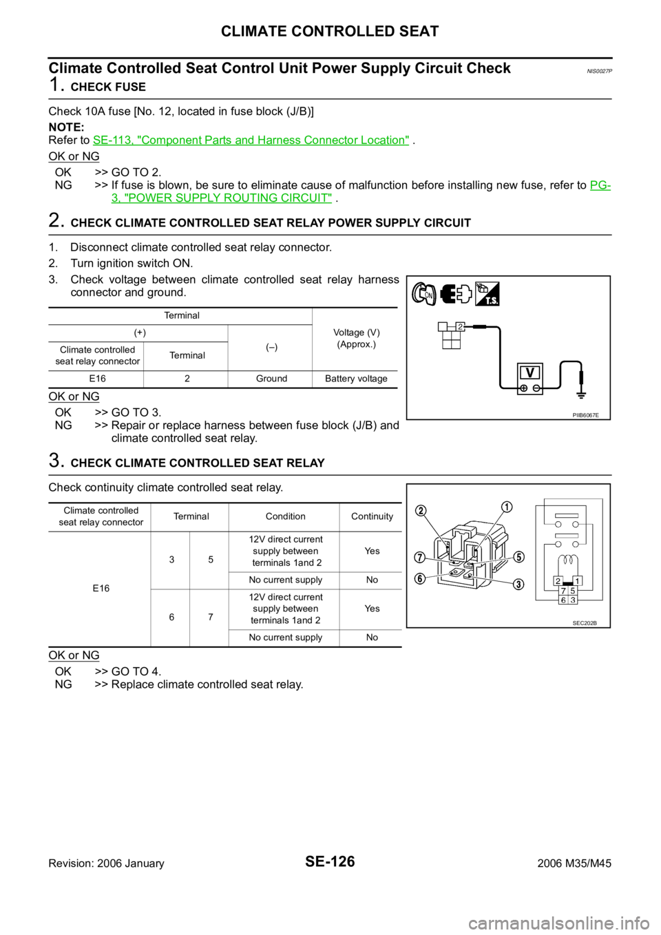
2. CHECK CLIMATE CONTROLLED SEAT RELAY POWER SUPPLY CIRCUIT
1. Disconnect climate controlled seat relay connector.
2. Turn ignition switch ON.
3. Check voltage between climate controlled seat relay harness
connector and ground.
OK or NG
OK >> GO TO 3.
NG >> Repair or replace harness between fuse block (J/B) and
climate controlled seat relay.
3. CHECK CLIMATE CONTROLLED SEAT RELAY
Check continuity climate controlled seat relay.
OK or NG
OK >> GO TO 4.
NG >> Replace climate controlled seat relay.
Terminal
Voltage (V)
(Approx.) (+)
(–)
Climate controlled
seat relay connectorTerminal
E16 2 Ground Battery voltage
PIIB6067E
Climate controlled
seat relay connectorTerminal Condition Continuity
E163512V direct current
supply between
terminals 1and 2Ye s
No current supply No
6712V direct current
supply between
terminals 1and 2Ye s
No current supply No
SEC202B
Page 5308 of 5621
CLIMATE CONTROLLED SEAT
SE-127
C
D
E
F
G
H
J
K
L
MA
B
SE
Revision: 2006 January2006 M35/M45
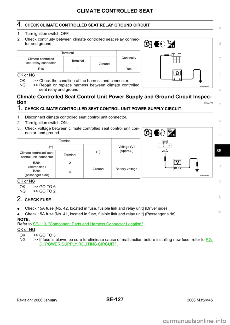
4. CHECK CLIMATE CONTROLLED SEAT RELAY GROUND CIRCUIT
1. Turn ignition switch OFF.
2. Check continuity between climate controlled seat relay connec-
tor and ground.
OK or NG
OK >> Check the condition of the harness and connector.
NG >> Repair or replace harness between climate controlled
seat relay and ground.
Climate Controlled Seat Control Unit Power Supply and Ground Circuit Inspec-
tion
NIS0027Q
1. CHECK CLIMATE CONTROLLED SEAT CONTROL UNIT POWER SUPPLY CIRCUIT
1. Disconnect climate controlled seat control unit connector.
2. Turn ignition switch ON.
3. Check voltage between climate controlled seat control unit con-
nector and ground.
OK or NG
OK >> GO TO 6.
NG >> GO TO 2.
2. CHECK FUSE
Check 15A fuse [No. 42, located in fuse, fusible link and relay unit] (Driver side)
Check 15A fuse [No. 41, located in fuse, fusible link and relay unit] (Passenger side)
NOTE:
Refer to SE-113, "
Component Parts and Harness Connector Location" .
OK or NG
OK >> GO TO 3.
NG >> If fuse is blown, be sure to eliminate cause of malfunction before installing new fuse, refer to PG-
3, "POWER SUPPLY ROUTING CIRCUIT" .
Terminal
Continuity
Climate controlled
seat relay connectorTerminal
Ground
E16 1 Yes
PIIB6068E
Terminal
Voltage (V)
(Approx.) (+)
(–)
Climate controlled seat
control unit connectorTerminal
B284
(driver side)
B294
(passenger side)2
Ground Battery voltage
4
PIIB6069E
Page 5333 of 5621
SE-152
HEATED SEAT
Revision: 2006 January2006 M35/M45
Rear Heated Seat Power Supply and Ground Circuit InspectionNIS00287
1. CHECK FUSIBLE LINK AND FUSE
Check 50A fusible link (letter F located in the fuse and fusible link box).
Check 15A fuse (No.38, located in fuse block).
Check circuit breaker.
NOTE:
Refer to SE-143, "
Component Parts and Harness Connector Location" .
OK or NG
OK >> GO TO 2.
NG >> If fuse or circuit breaker is blown, be sure to eliminate cause of malfunction before installing new
fuse or new circuit breaker, refer to PG-3, "
POWER SUPPLY ROUTING CIRCUIT" .
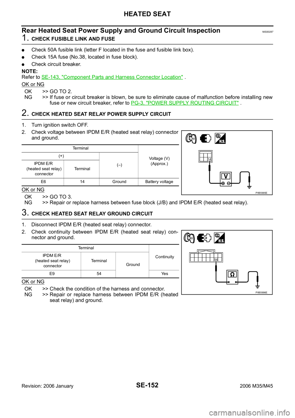
2. CHECK HEATED SEAT RELAY POWER SUPPLY CIRCUIT
1. Turn ignition switch OFF.
2. Check voltage between IPDM E/R (heated seat relay) connector
and ground.
OK or NG
OK >> GO TO 3.
NG >> Repair or replace harness between fuse block (J/B) and IPDM E/R (heated seat relay).
3. CHECK HEATED SEAT RELAY GROUND CIRCUIT
1. Disconnect IPDM E/R (heated seat relay) connector.
2. Check continuity between IPDM E/R (heated seat relay) con-
nector and ground.
OK or NG
OK >> Check the condition of the harness and connector.
NG >> Repair or replace harness between IPDM E/R (heated
seat relay) and ground.
Terminal
Voltage (V)
(Approx.) (+)
(–) IPDM E/R
(heated seat relay)
connectorTerminal
E6 14 Ground Battery voltage
PIIB5995E
Te r m i n a l
Continuity IPDM E/R
(heated seat relay)
connectorTerminal
Ground
E9 54 Yes
PIIB5996E
Page 5348 of 5621
FRONT SEAT
SE-167
C
D
E
F
G
H
J
K
L
MA
B
SE
Revision: 2006 January2006 M35/M45
Removal and InstallationNIS0028G
CAUTION:
When removing and installing, use shop cloths to protect parts from damage.
REMOVAL
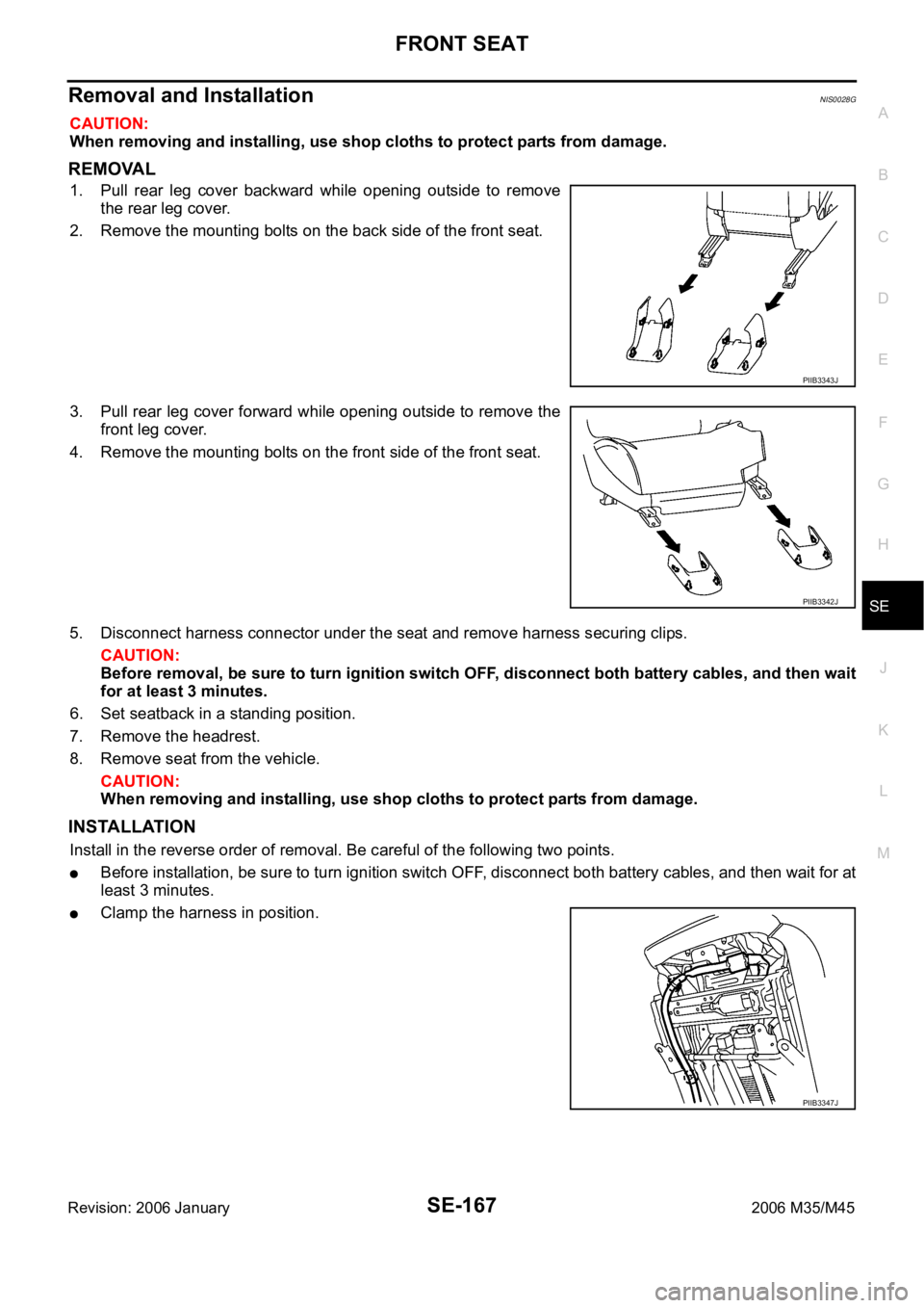
1. Pull rear leg cover backward while opening outside to remove
the rear leg cover.
2. Remove the mounting bolts on the back side of the front seat.
3. Pull rear leg cover forward while opening outside to remove the
front leg cover.
4. Remove the mounting bolts on the front side of the front seat.
5. Disconnect harness connector under the seat and remove harness securing clips.
CAUTION:
Before removal, be sure to turn ignition switch OFF, disconnect both battery cables, and then wait
for at least 3 minutes.
6. Set seatback in a standing position.
7. Remove the headrest.
8. Remove seat from the vehicle.
CAUTION:
When removing and installing, use shop cloths to protect parts from damage.
INSTALLATION
Install in the reverse order of removal. Be careful of the following two points.
Before installation, be sure to turn ignition switch OFF, disconnect both battery cables, and then wait for at
least 3 minutes.
Clamp the harness in position.
PIIB3343J
PIIB3342J
PIIB3347J
Page 5349 of 5621
SE-168
FRONT SEAT
Revision: 2006 January2006 M35/M45
Disassembly and AssemblyNIS0028H
SEATBACK
Disassembly
1. Remove seatback trim and seatback pad.
NOTE:
Seatback trim and seatback pad can be removed without removing seatback assembly from seat body.
Remove the retainer from the lower side of seatback board.
Disconnect the clips and pawls, and then remove the seatback
board.
: Pawl
: Clip
Remove the seatback hinge mounting bolts.
Remove the retainer on the back side of the seatback.
Remove the seat speaker grills. (Applied 5.1 ch BOSE studio surround® system models.) Refer to AV-
287, "Seat Speaker" .
Remove the headrest holder.
CAUTION:
Before installing headrest holder, check its orientation
(front/rear and right/left).
Disconnect the clip, and then remove the reclining device cover.
Remove the screws, and then remove the seatback upper fin-
isher.
PIIB3344J
PIIB3353J
PIIB4084J
PIIB3355J
Page 5350 of 5621
FRONT SEAT
SE-169
C
D
E
F
G
H
J
K
L
MA
B
SE
Revision: 2006 January2006 M35/M45
Remove the bracket mounting nuts.
Remove seatback trim and pad from seatback frame.
Remove the hog rings to separate the trim and pad.
2. Remove seatback frame.
Remove seat speaker. (Applied 5.1 ch BOSE studio surround® system models) Refer to AV-287, "Seat
Speaker" .
Remove the bands, and then remove seatback thermal electrical device (TED) assembly.
Remove the seat harness assembly from seatback assembly.
Remove the bolts, and then remove seatback frame from seat cushion frame.
Assembly
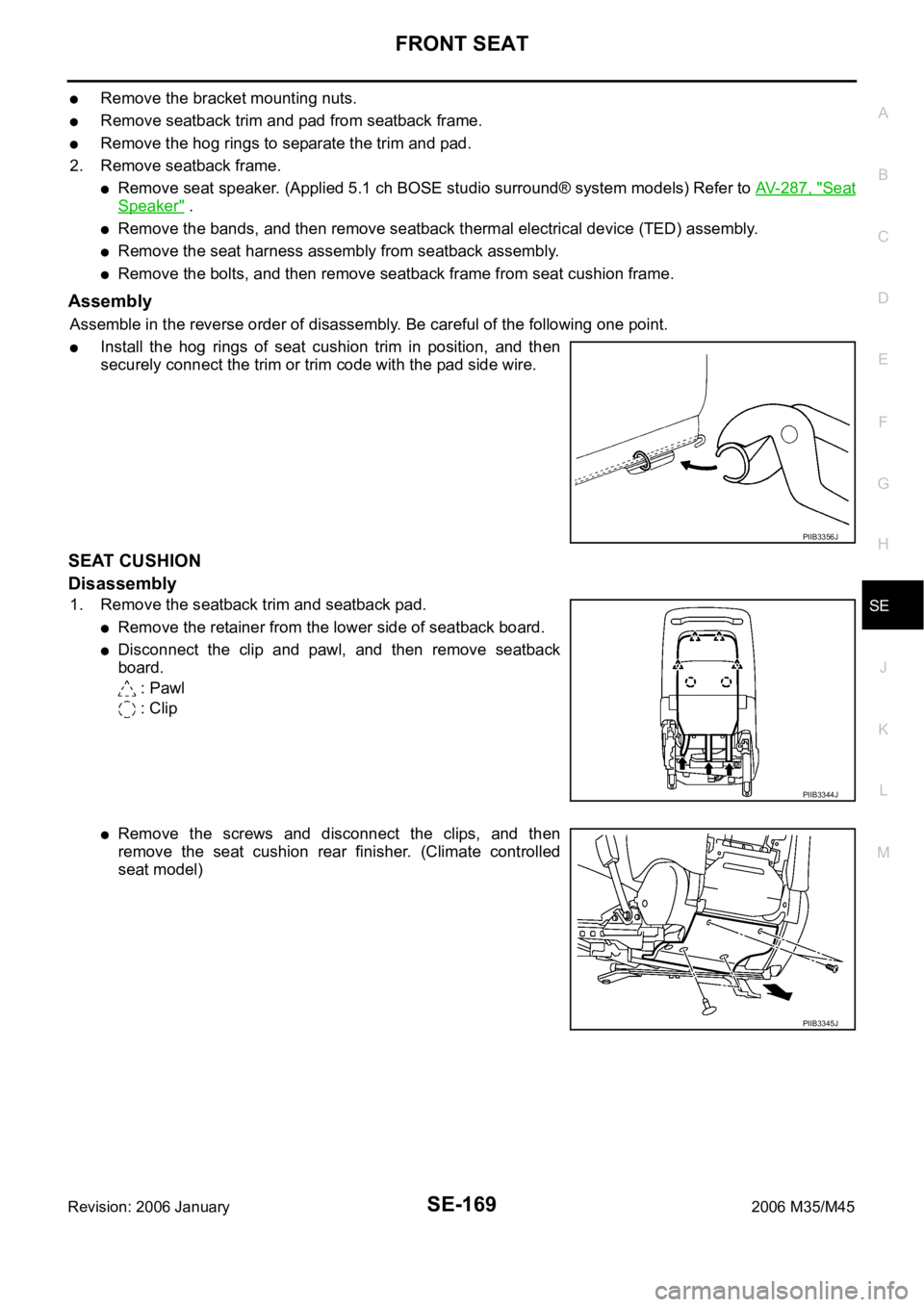
Assemble in the reverse order of disassembly. Be careful of the following one point.
Install the hog rings of seat cushion trim in position, and then
securely connect the trim or trim code with the pad side wire.
SEAT CUSHION
Disassembly
1. Remove the seatback trim and seatback pad.
Remove the retainer from the lower side of seatback board.
Disconnect the clip and pawl, and then remove seatback
board.
: Pawl
: Clip
Remove the screws and disconnect the clips, and then
remove the seat cushion rear finisher. (Climate controlled
seat model)
PIIB3356J
PIIB3344J
PIIB3345J
Page 5352 of 5621
FRONT SEAT
SE-171
C
D
E
F
G
H
J
K
L
MA
B
SE
Revision: 2006 January2006 M35/M45
Remove driver's seat control unit. (Driver's seat only)
Remove the driver seat control switch.
Remove seat cushion finisher B and seat cushion finisher C.
Remove seat harnesses.
Assembly
Assemble in the reverse order of disassembly. Be careful of the following two points.
Install the hog rings of seat cushion trim in position, and then
securely connect the trim or trim code with the pad side wire.
Clamp the harness in position.
CLIMATE CONTROLLED SEAT
Blower Filter Replacement
Put your hand behind front seat cushion, pull filter downward and
remove it. Replace filter with a new one.
NOTE:
When replacing, be sure to set the front seat lifter to the top
position.
When installing, do not confuse up-down direction of the filter.
PIIB3357J
PIIB3356J
PIIB6502E