2006 INFINITI M35 sensor
[x] Cancel search: sensorPage 3322 of 5621
![INFINITI M35 2006 Factory Service Manual CYLINDER BLOCK
EM-259
[VK45DE]
C
D
E
F
G
H
I
J
K
L
MA
EM
Revision: 2006 January2006 M35/M45
16. Install knock sensor.
Install it with its connector facing the rear of engine.
Install the sub-harness INFINITI M35 2006 Factory Service Manual CYLINDER BLOCK
EM-259
[VK45DE]
C
D
E
F
G
H
I
J
K
L
MA
EM
Revision: 2006 January2006 M35/M45
16. Install knock sensor.
Install it with its connector facing the rear of engine.
Install the sub-harness](/manual-img/42/57023/w960_57023-3321.png)
CYLINDER BLOCK
EM-259
[VK45DE]
C
D
E
F
G
H
I
J
K
L
MA
EM
Revision: 2006 January2006 M35/M45
16. Install knock sensor.
Install it with its connector facing the rear of engine.
Install the sub-harness with its shorter branch line to the right
bank.
CAUTION:
Do not tighten mounting bolts while holding connector.
If any impact by dropping is applied to knock sensor,
replace it with new one.
NOTE:
Make sure that there is no foreign material on the cylinder
block mating surface and the back surface of knock sensor.
Make sure that knock sensor does not interfere with other parts.
17. Note the following, and assemble in the reverse order of disassembly after this step.
Drive plate
When installing drive plate to crankshaft, be sure to correctly
align crankshaft side guide pin and drive plate side guide pin
hole.
CAUTION:
If these are not aligned correctly, engine runs roughly
and “MIL” turns on.
Install drive plate, reinforcement plate and pilot converter (if
not installed in step 4) as shown in the figure.
Face chamfered or rounded edge side to crankshaft.
Holding ring gear with ring gear stopper [SST: J-45476].
Tighten mounting bolts crosswise over several times.
When install pilot converter, using drift [outer diameter:
approx. 35 mm (1.38 in)]. Press-fit as far as it will go.
How to Select Piston and Bearing NBS004PO
DESCRIPTION
PBIC0105E
PBIC0106E
PBIC1965E
Selection points Selection parts Selection items Selection methods
Between cylinder block and
crankshaftMain bearingMain bearing grade
(bearing thickness)Determined by match of cylin-
der block bearing housing
grade (inner diameter of hous-
ing) and crankshaft journal
grade (outer diameter of jour-
nal)
Between crankshaft and con-
necting rodConnecting rod bearingConnecting rod bearing grade
(bearing thickness)Combining service grades for
connecting rod big end diame-
ter and crankshaft pin outer
diameter determine connecting
rod bearing selection.
Between cylinder block and pis-
tonPiston and piston pin assembly
(Piston is available together
with piston pin as assembly.)Piston grade
(piston skirt diameter)Piston grade = cylinder bore
grade (inner diameter of bore)
Between piston and connecting
rod*———
Page 3353 of 5621
EX-2
PREPARATION
Revision: 2006 January2006 M35/M45
PREPARATIONPFP:00002
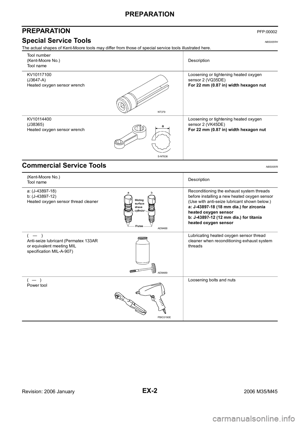
Special Service ToolsNBS005RH
The actual shapes of Kent-Moore tools may differ from those of special service tools illustrated here.
Commercial Service ToolsNBS005RI
Tool number
(Kent-Moore No.)
Tool nameDescription
KV10117100
(J3647-A)
Heated oxygen sensor wrenchLoosening or tightening heated oxygen
sensor 2 (VQ35DE)
For 22 mm (0.87 in) width hexagon nut
KV10114400
(J38365)
Heated oxygen sensor wrenchLoosening or tightening heated oxygen
sensor 2 (VK45DE)
For 22 mm (0.87 in) width hexagon nut
NT379
S-NT636
(Kent-Moore No.)
Tool nameDescription
a: (J-43897-18)
b: (J-43897-12)
Heated oxygen sensor thread cleanerReconditioning the exhaust system threads
before installing a new heated oxygen sensor
(Use with anti-seize lubricant shown below.)
a: J-43897-18 (18 mm dia.) for zirconia
heated oxygen sensor
b: J-43897-12 (12 mm dia.) for titania
heated oxygen sensor
(—)
Anti-seize lubricant (Permatex 133AR
or equivalent meeting MIL
specification MIL-A-907)Lubricating heated oxygen sensor thread
cleaner when reconditioning exhaust system
threads
( — )
Power toolLoosening bolts and nuts
AEM488
AEM489
PBIC0190E
Page 3355 of 5621
EX-4
EXHAUST SYSTEM
Revision: 2006 January2006 M35/M45
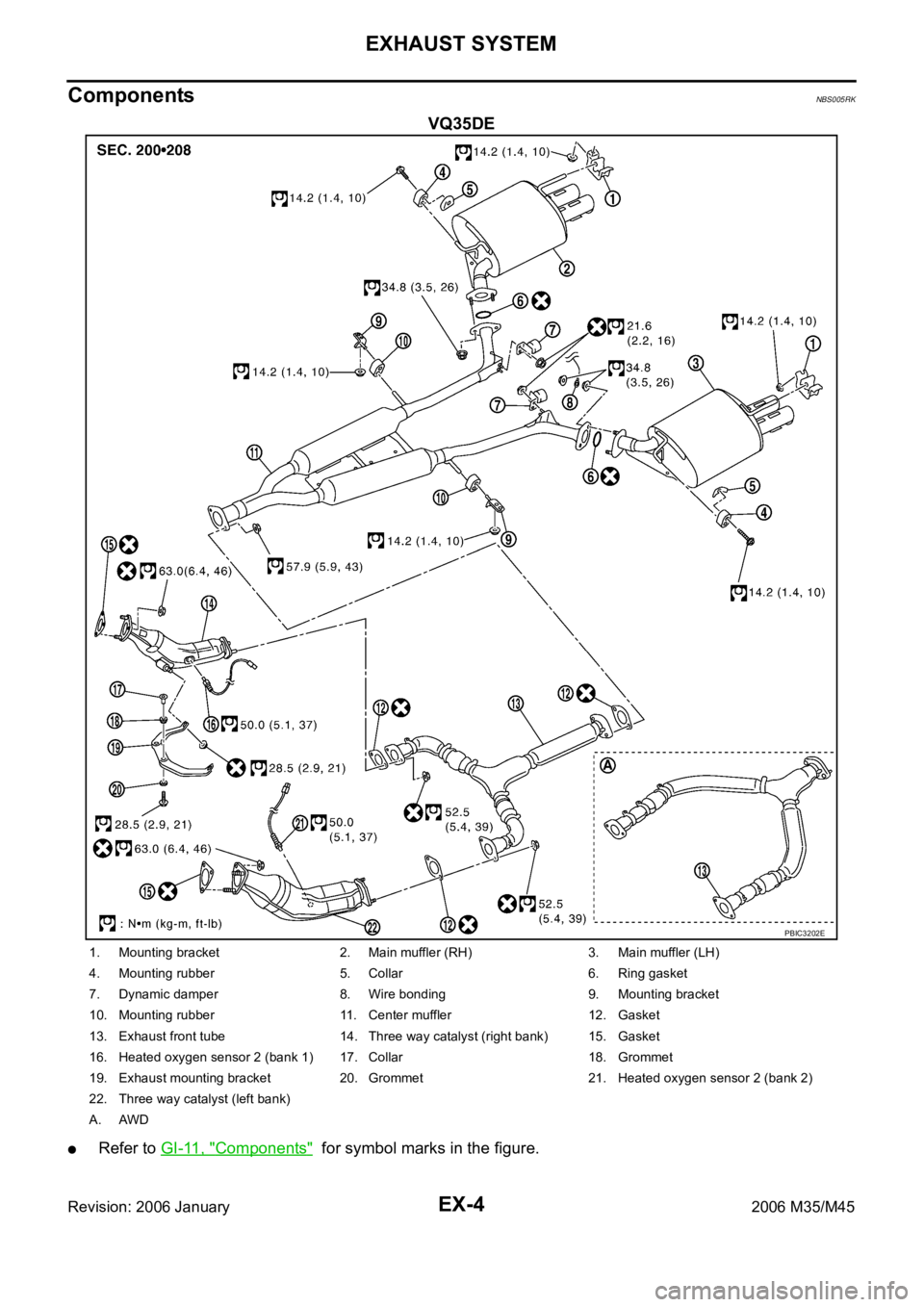
ComponentsNBS005RK
VQ35DE
Refer to GI-11, "Components" for symbol marks in the figure.
PBIC3202E
1. Mounting bracket 2. Main muffler (RH) 3. Main muffler (LH)
4. Mounting rubber 5. Collar 6. Ring gasket
7. Dynamic damper 8. Wire bonding 9. Mounting bracket
10. Mounting rubber 11. Center muffler 12. Gasket
13. Exhaust front tube 14. Three way catalyst (right bank) 15. Gasket
16. Heated oxygen sensor 2 (bank 1) 17. Collar 18. Grommet
19. Exhaust mounting bracket 20. Grommet 21. Heated oxygen sensor 2 (bank 2)
22. Three way catalyst (left bank)
A. AWD
Page 3356 of 5621
EXHAUST SYSTEM
EX-5
C
D
E
F
G
H
I
J
K
L
MA
EX
Revision: 2006 January2006 M35/M45
Removal and InstallationNBS005RL
CAUTION:
Be sure to use genuine exhaust system parts or equivalents which are specially designed for heat
resistance, corrosion resistance, and shape.
Perform the operation with the exhaust system fully cooled down because the system will be hot
just after engine stops.
Be careful not to cut your hand on the heat insulator edge.
REMOVAL
Disconnect each joint and mounting using power tool.
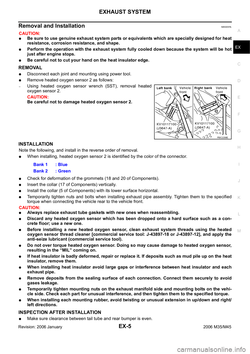
Remove heated oxygen sensor 2 as follows:
–Using heated oxygen sensor wrench (SST), removal heated
oxygen sensor 2.
CAUTION:
Be careful not to damage heated oxygen sensor 2.
INSTALLATION
Note the following, and install in the reverse order of removal.
When installing, heated oxygen sensor 2 is identified by the color of the connector.
Check for deformation of the grommets (18 and 20 of Components).
Insert the collar (17 of Components) vertically.
Install the collar (5 of Components) with its lower surface horizontal.
Temporarily tighten nuts and bolts when installing exhaust pipe assembly. Tighten them to the specified
torque when connecting the vehicle rear to the vehicle front.
CAUTION:
Always replace exhaust tube gaskets with new ones when reassembling.
Discard any heated oxygen sensor which has been dropped onto a hard surface such as a con-
crete floor; use a new one.
Before installing a new heated oxygen sensor, clean exhaust system threads using the heated
oxygen sensor thread cleaner [commercial service tool: J-43897-18 or J-43897-12], and apply the
anti-seize lubricant (commercial service tool).
Do not over torque heated oxygen sensor. Doing so may cause damage to heated oxygen sensor,
resulting in the “MIL” coming on.
If heat insulator is badly deformed, repair or replace it. If deposits such as mud pile up on the heat
insulator, remove them.
When installing heat insulator avoid large gaps or interference between heat insulator and each
exhaust pipe.
Remove deposits from the sealing surface of each connection. Connect them securely to avoid
gases leakage.
Temporarily tighten mounting nuts on the exhaust manifold side and mounting bolts on the vehi-
cle side. Check each part for unusual interference, and then tighten them to the specified torque.
When installing each mounting rubber, avoid twisting or unusual extension in up/down and right/
left directions.
INSPECTION AFTER INSTALLATION
Make sure clearance between tail tube and rear bumper is even.
PBIC2298E
Bank 1 : Blue
Bank 2 : Green
Page 3357 of 5621
EX-6
EXHAUST SYSTEM
Revision: 2006 January2006 M35/M45
With engine running, check exhaust tube joints for gas leakage and unusual noises.
Check to ensure that mounting brackets and mounting rubbers are installed properly and free from undue
stress. Improper installation could result in excessive noise and vibration.
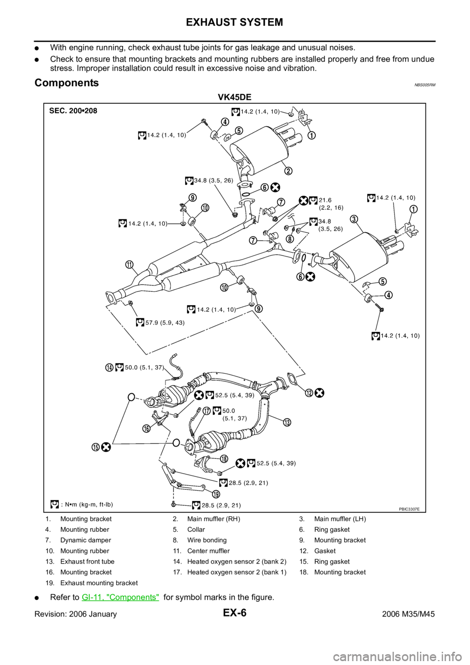
ComponentsNBS005RM
VK45DE
Refer to GI-11, "Components" for symbol marks in the figure.
PBIC3307E
1. Mounting bracket 2. Main muffler (RH) 3. Main muffler (LH)
4. Mounting rubber 5. Collar 6. Ring gasket
7. Dynamic damper 8. Wire bonding 9. Mounting bracket
10. Mounting rubber 11. Center muffler 12. Gasket
13. Exhaust front tube 14. Heated oxygen sensor 2 (bank 2) 15. Ring gasket
16. Mounting bracket 17. Heated oxygen sensor 2 (bank 1) 18. Mounting bracket
19. Exhaust mounting bracket
Page 3358 of 5621
EXHAUST SYSTEM
EX-7
C
D
E
F
G
H
I
J
K
L
MA
EX
Revision: 2006 January2006 M35/M45
Removal and installationNBS005RN
CAUTION:
Be sure to use genuine exhaust system parts or equivalents which are specially designed for heat
resistance, corrosion resistance, and shape.
Perform the operation with the exhaust system fully cooled down because the system will be hot
just after engine stops.
Be careful not to cut your hand on the heat insulator edge.
REMOVAL
Disconnect each joint and mounting using power tool.
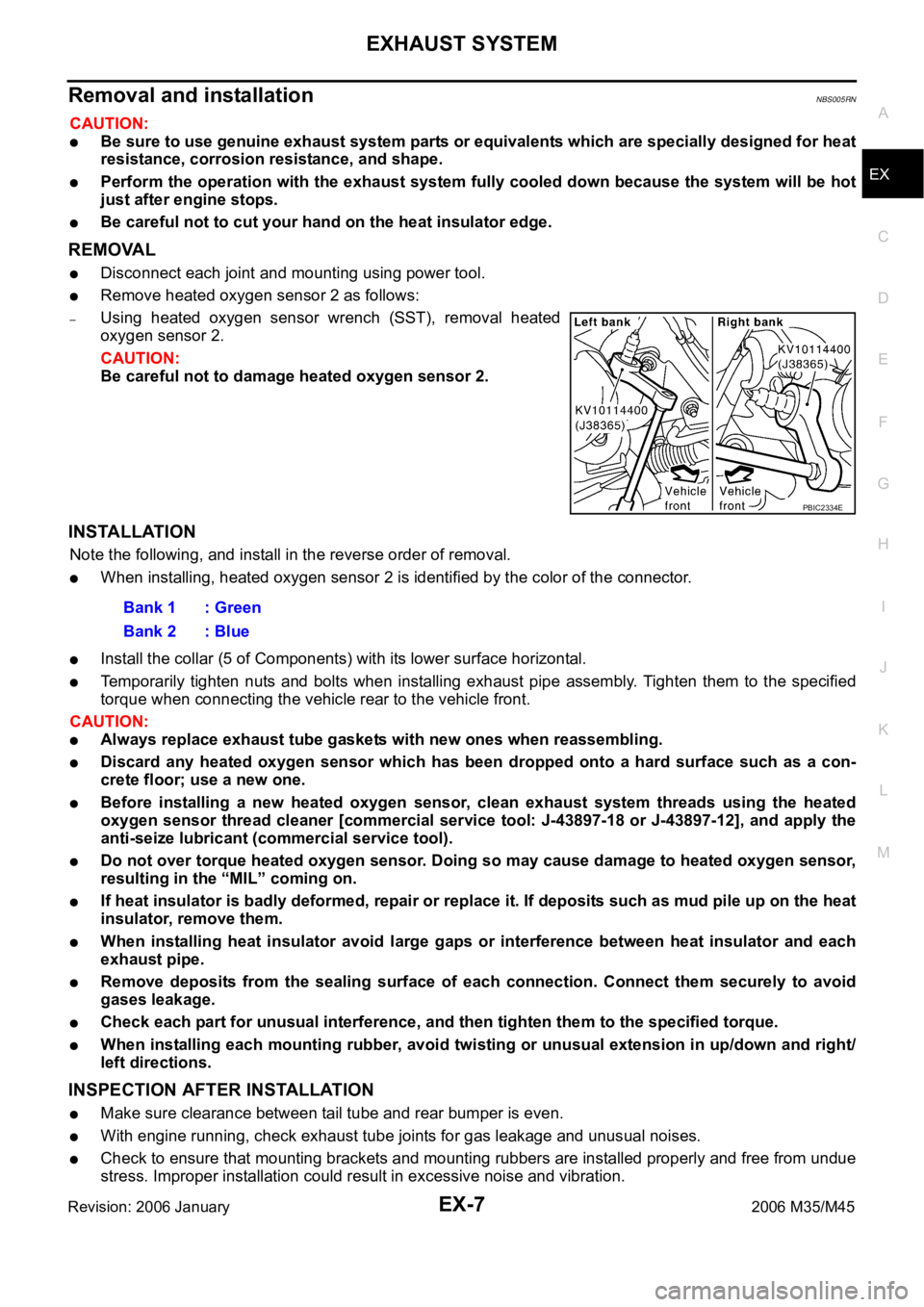
Remove heated oxygen sensor 2 as follows:
–Using heated oxygen sensor wrench (SST), removal heated
oxygen sensor 2.
CAUTION:
Be careful not to damage heated oxygen sensor 2.
INSTALLATION
Note the following, and install in the reverse order of removal.
When installing, heated oxygen sensor 2 is identified by the color of the connector.
Install the collar (5 of Components) with its lower surface horizontal.
Temporarily tighten nuts and bolts when installing exhaust pipe assembly. Tighten them to the specified
torque when connecting the vehicle rear to the vehicle front.
CAUTION:
Always replace exhaust tube gaskets with new ones when reassembling.
Discard any heated oxygen sensor which has been dropped onto a hard surface such as a con-
crete floor; use a new one.
Before installing a new heated oxygen sensor, clean exhaust system threads using the heated
oxygen sensor thread cleaner [commercial service tool: J-43897-18 or J-43897-12], and apply the
anti-seize lubricant (commercial service tool).
Do not over torque heated oxygen sensor. Doing so may cause damage to heated oxygen sensor,
resulting in the “MIL” coming on.
If heat insulator is badly deformed, repair or replace it. If deposits such as mud pile up on the heat
insulator, remove them.
When installing heat insulator avoid large gaps or interference between heat insulator and each
exhaust pipe.
Remove deposits from the sealing surface of each connection. Connect them securely to avoid
gases leakage.
Check each part for unusual interference, and then tighten them to the specified torque.
When installing each mounting rubber, avoid twisting or unusual extension in up/down and right/
left directions.
INSPECTION AFTER INSTALLATION
Make sure clearance between tail tube and rear bumper is even.
With engine running, check exhaust tube joints for gas leakage and unusual noises.
Check to ensure that mounting brackets and mounting rubbers are installed properly and free from undue
stress. Improper installation could result in excessive noise and vibration.
PBIC2334E
Bank 1 : Green
Bank 2 : Blue
Page 3364 of 5621
FRONT WHEEL HUB AND KNUCKLE
FAX-5
C
E
F
G
H
I
J
K
L
MA
B
FA X
Revision: 2006 January2006 M35/M45
FRONT WHEEL HUB AND KNUCKLEPFP:40202
On-Vehicle Inspection and ServiceNDS000FF
Make sure that the mounting conditions (looseness, backlash) of each component and component conditions
(wear, damage) are normal.
WHEEL BEARING INSPECTION
Move wheel hub and bearing assembly in the axial direction by hand. Make sure there is no looseness of
wheel bearing.
Rotate wheel hub and make sure that is no unusual noise or other irregular conditions. If there is any of
irregular conditions, replace wheel hub and bearing assembly
Removal and InstallationNDS000FG
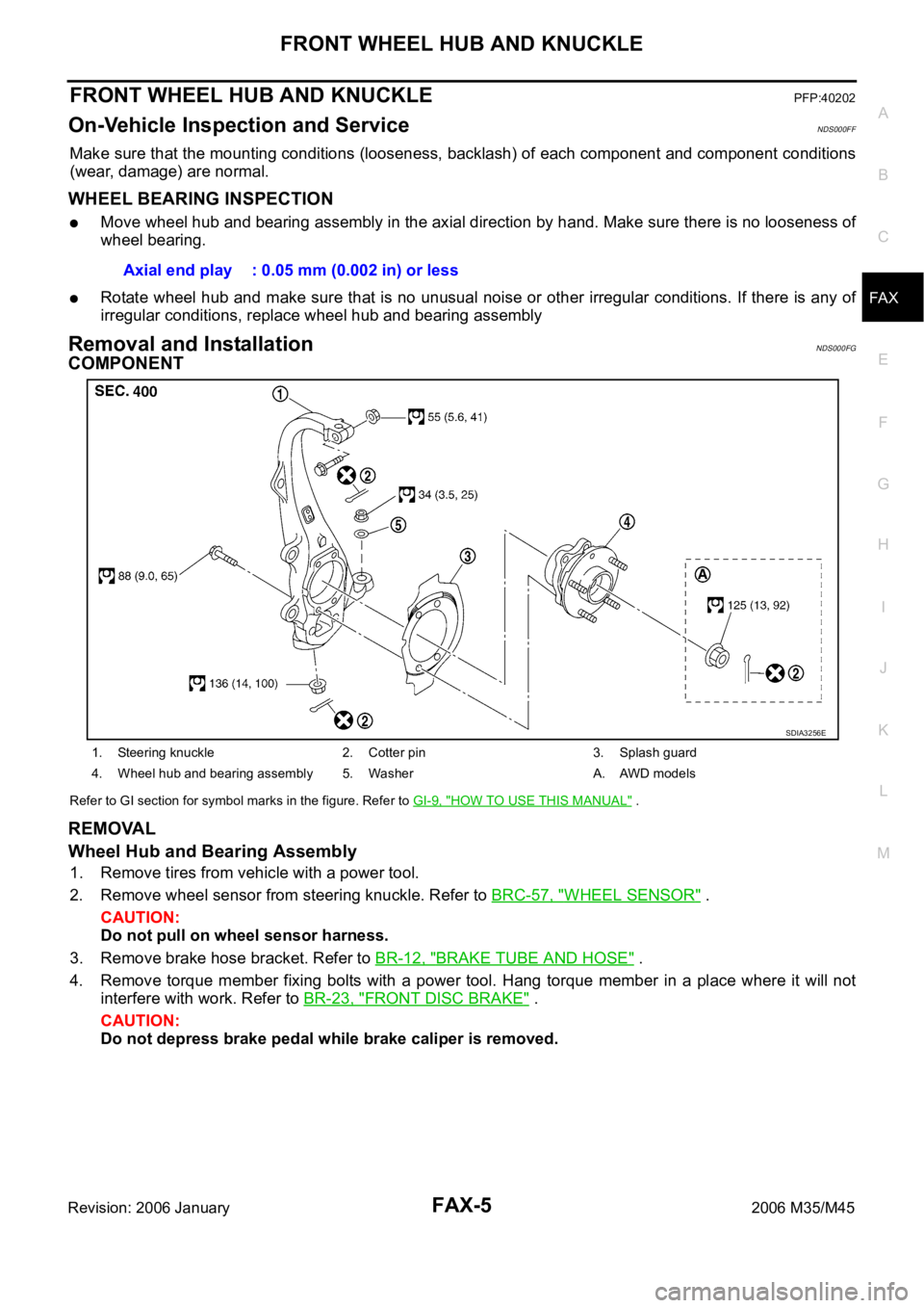
COMPONENT
Refer to GI section for symbol marks in the figure. Refer to GI-9, "HOW TO USE THIS MANUAL" .
REMOVAL
Wheel Hub and Bearing Assembly
1. Remove tires from vehicle with a power tool.
2. Remove wheel sensor from steering knuckle. Refer to BRC-57, "
WHEEL SENSOR" .
CAUTION:
Do not pull on wheel sensor harness.
3. Remove brake hose bracket. Refer to BR-12, "
BRAKE TUBE AND HOSE" .
4. Remove torque member fixing bolts with a power tool. Hang torque member in a place where it will not
interfere with work. Refer to BR-23, "
FRONT DISC BRAKE" .
CAUTION:
Do not depress brake pedal while brake caliper is removed.Axial end play : 0.05 mm (0.002 in) or less
1. Steering knuckle 2. Cotter pin 3. Splash guard
4. Wheel hub and bearing assembly 5. Washer A. AWD models
SDIA3256E
Page 3366 of 5621
FRONT WHEEL HUB AND KNUCKLE
FAX-7
C
E
F
G
H
I
J
K
L
MA
B
FA X
Revision: 2006 January2006 M35/M45
INSTALLATION
Installation is the reverse order of the removal. For tightening torque, refer to FAX-5, "COMPONENT" .
Perform the final tightening of each of parts under unladen conditions, which were removed when remov-
ing wheel hub and bearing assembly and steering knuckle. Check the wheel alignment. Refer to FSU-6,
"Wheel Alignment Inspection" (2WD), FSU-23, "Wheel Alignment Inspection" (AWD).
Adjust neutral position of steering angle sensor after checking the wheel alignment. Refer to BRC-6,
"Adjustment of Steering Angle Sensor Neutral Position" .
Check wheel sensor harness for proper connection. Refer to BRC-57, "WHEEL SENSOR" .
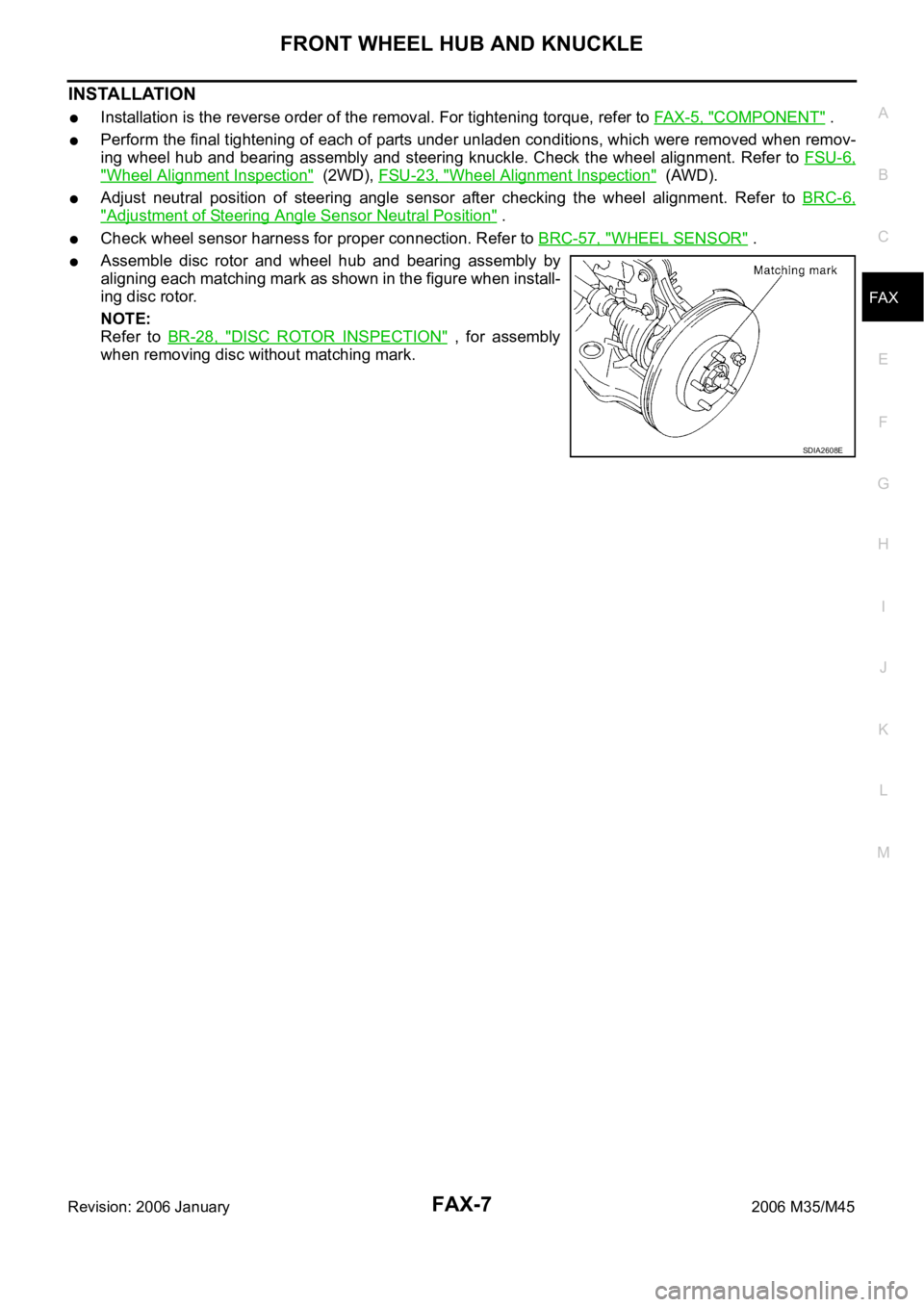
Assemble disc rotor and wheel hub and bearing assembly by
aligning each matching mark as shown in the figure when install-
ing disc rotor.
NOTE:
Refer to BR-28, "
DISC ROTOR INSPECTION" , for assembly
when removing disc without matching mark.
SDIA2608E