Page 4461 of 5621
LT-34
HEADLAMP (FOR USA) - CONVENTIONAL TYPE -
Revision: 2006 January2006 M35/M45
6. CHECK CIRCUIT BETWEEN IPDM E/R AND FRONT COMBINATION LAMP
1. Turn ignition switch OFF.
2. Disconnect IPDM E/R connector.
3. Check continuity between IPDM E/R harness connector (A) and
front combination lamp (RH and LH) harness connector (B).
4. Check continuity between IPDM E/R harness connector (A) and
ground.
OK or NG
OK >> Replace IPDM E/R. Refer to PG-31, "Removal and Installation of IPDM E/R" .
NG >> Repair harness or connector.
CircuitAB
Continuity
Connector Terminal Connector Terminal
RH
E720 E47 8
Ye s
LH 30 E54 8
A
GroundContinuity
Connector Terminal
RH
E720
No
LH 30
SKIB4760E
Page 4463 of 5621
LT-36
HEADLAMP (FOR USA) - CONVENTIONAL TYPE -
Revision: 2006 January2006 M35/M45
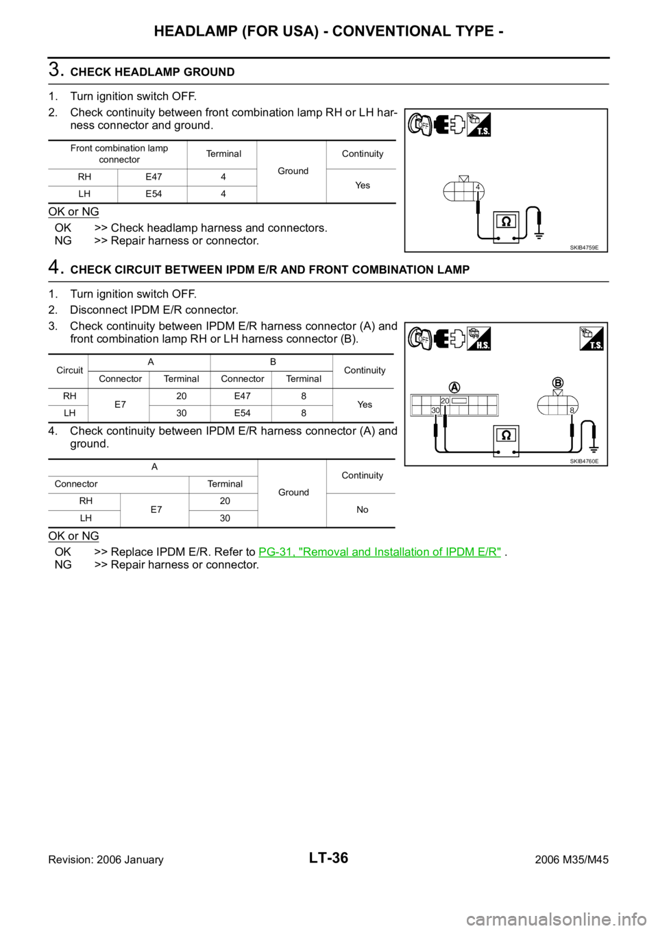
3. CHECK HEADLAMP GROUND
1. Turn ignition switch OFF.
2. Check continuity between front combination lamp RH or LH har-
ness connector and ground.
OK or NG
OK >> Check headlamp harness and connectors.
NG >> Repair harness or connector.
4. CHECK CIRCUIT BETWEEN IPDM E/R AND FRONT COMBINATION LAMP
1. Turn ignition switch OFF.
2. Disconnect IPDM E/R connector.
3. Check continuity between IPDM E/R harness connector (A) and
front combination lamp RH or LH harness connector (B).
4. Check continuity between IPDM E/R harness connector (A) and
ground.
OK or NG
OK >> Replace IPDM E/R. Refer to PG-31, "Removal and Installation of IPDM E/R" .
NG >> Repair harness or connector.
Front combination lamp
connectorTerminal
GroundContinuity
RH E47 4
Ye s
LH E54 4
SKIB4759E
CircuitAB
Continuity
Connector Terminal Connector Terminal
RH
E720 E47 8
Ye s
LH 30 E54 8
A
GroundContinuity
Connector Terminal
RH
E720
No
LH 30
SKIB4760E
Page 4464 of 5621
HEADLAMP (FOR USA) - CONVENTIONAL TYPE -
LT-37
C
D
E
F
G
H
I
J
L
MA
B
LT
Revision: 2006 January2006 M35/M45
Headlamps Do Not Turn OFFNKS003OF
1. CHECK HEADLAMP TURN OFF
Make sure that lighting switch is OFF. And make sure headlamp turns off when ignition switch is turned OFF.
OK or NG
OK >> GO TO 3.
NG >> GO TO 2.
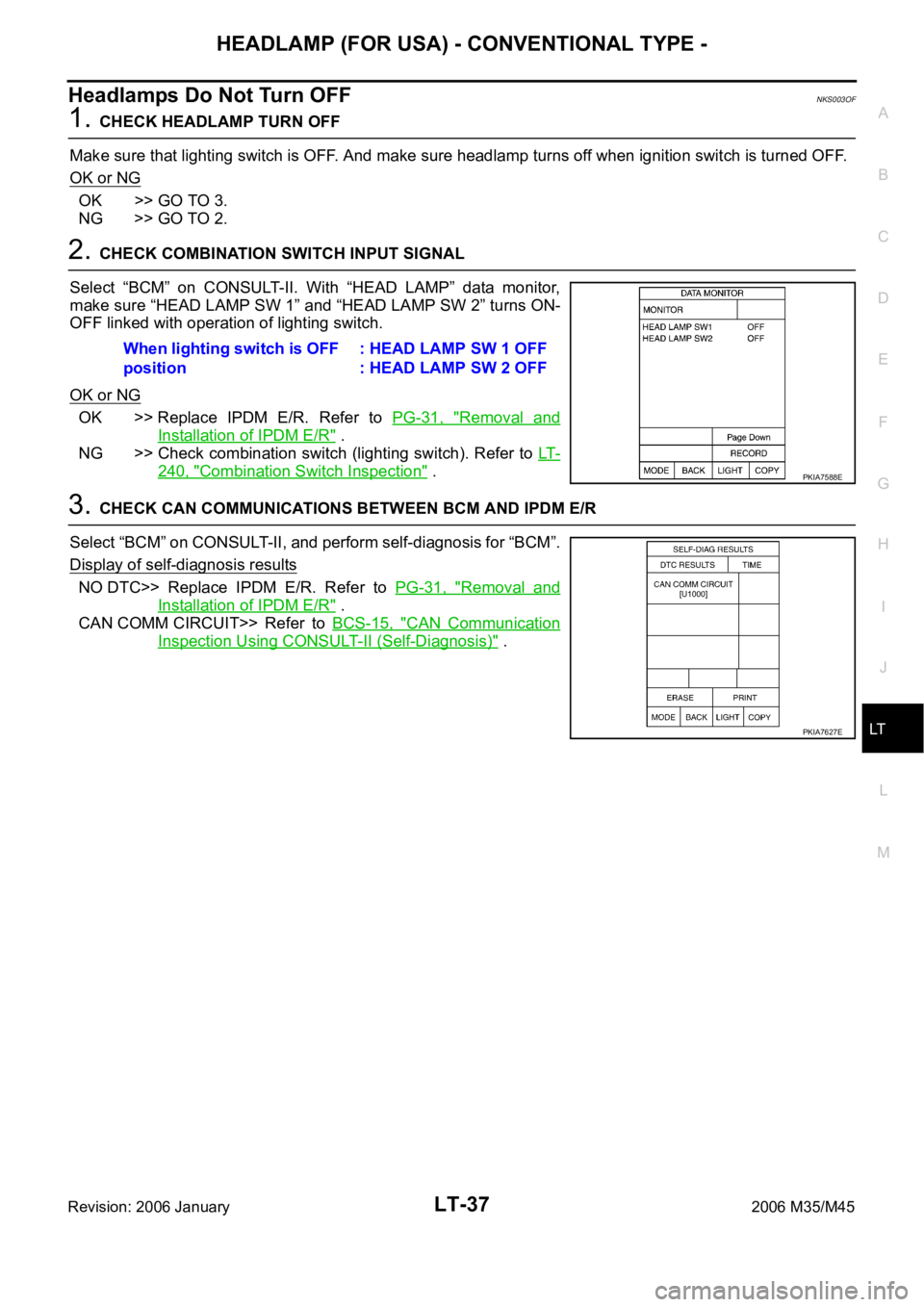
2. CHECK COMBINATION SWITCH INPUT SIGNAL
Select “BCM” on CONSULT-II. With “HEAD LAMP” data monitor,
make sure “HEAD LAMP SW 1” and “HEAD LAMP SW 2” turns ON-
OFF linked with operation of lighting switch.
OK or NG
OK >> Replace IPDM E/R. Refer to PG-31, "Removal and
Installation of IPDM E/R" .
NG >> Check combination switch (lighting switch). Refer to LT-
240, "Combination Switch Inspection" .
3. CHECK CAN COMMUNICATIONS BETWEEN BCM AND IPDM E/R
Select “BCM” on CONSULT-II, and perform self-diagnosis for “BCM”.
Display of self-diagnosis results
NO DTC>> Replace IPDM E/R. Refer to PG-31, "Removal and
Installation of IPDM E/R" .
CAN COMM CIRCUIT>> Refer to BCS-15, "
CAN Communication
Inspection Using CONSULT-II (Self-Diagnosis)" . When lighting switch is OFF
position: HEAD LAMP SW 1 OFF
: HEAD LAMP SW 2 OFF
PKIA7588E
PKIA7627E
Page 4466 of 5621
HEADLAMP (FOR USA) - CONVENTIONAL TYPE -
LT-39
C
D
E
F
G
H
I
J
L
MA
B
LT
Revision: 2006 January2006 M35/M45
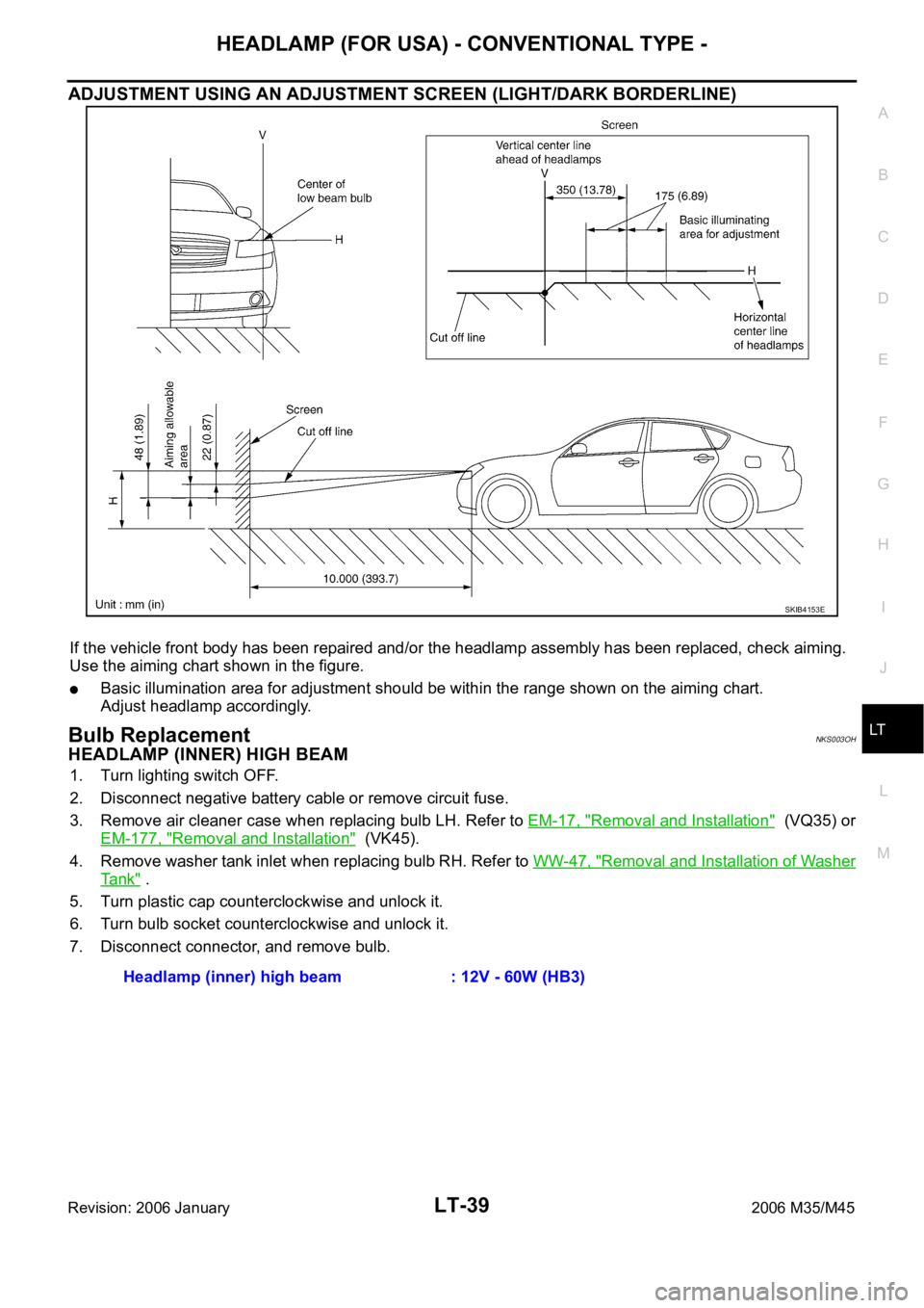
ADJUSTMENT USING AN ADJUSTMENT SCREEN (LIGHT/DARK BORDERLINE)
If the vehicle front body has been repaired and/or the headlamp assembly has been replaced, check aiming.
Use the aiming chart shown in the figure.
Basic illumination area for adjustment should be within the range shown on the aiming chart.
Adjust headlamp accordingly.
Bulb ReplacementNKS003OH
HEADLAMP (INNER) HIGH BEAM
1. Turn lighting switch OFF.
2. Disconnect negative battery cable or remove circuit fuse.
3. Remove air cleaner case when replacing bulb LH. Refer to EM-17, "
Removal and Installation" (VQ35) or
EM-177, "
Removal and Installation" (VK45).
4. Remove washer tank inlet when replacing bulb RH. Refer to WW-47, "
Removal and Installation of Washer
Ta n k" .
5. Turn plastic cap counterclockwise and unlock it.
6. Turn bulb socket counterclockwise and unlock it.
7. Disconnect connector, and remove bulb.
SKIB4153E
Headlamp (inner) high beam : 12V - 60W (HB3)
Page 4467 of 5621
LT-40
HEADLAMP (FOR USA) - CONVENTIONAL TYPE -
Revision: 2006 January2006 M35/M45
HEADLAMP (OUTER) LOW BEAM
1. Turn lighting switch OFF.
2. Disconnect negative battery cable or remove circuit fuse.
3. Remove fender protector (front). Refer to EI-20, "
Removal and Installation" .
4. Turn plastic cap counterclockwise and unlock it.
5. Unlock retaining spring and remove bulb from headlamp.
6. Remove the socket connected the bulb.
PARKING LAMP (CLEARANCE) LAMP
1. Turn bulb socket counterclockwise and unlock it.
2. Remove bulb from its socket.
FRONT TURN SIGNAL LAMP
1. Remove washer tank inlet when replaced bulb RH. Refer to WW-47, "Removal and Installation of Washer
Ta n k" .
Remove air cleaner case when replacing bulb LH. Refer to EM-17, "
Removal and Installation" (VQ35) or
EM-177, "
Removal and Installation" (VK45).
2. Turn bulb socket counterclockwise and unlock it.
3. Remove bulb from its socket.
FRONT SIDE MARKER LAMP
1. Remove fender protector (front) to obtain work space between the fender protector and fender.
2. Turn bulb socket counterclockwise and unlock it.
3. Remove bulb from its socket.
CAUTION:
After installing bulb, be sure to install plastic cap and socket securely to insure watertightness. Headlamp (outer) low beam : 12V - 55W (H1)
Parking lamp (Clearance lamps) : 12V - 5W
Front turn signal lamp : 12V - 21W
Front side marker lamp : 12V - 5W
Page 4468 of 5621
HEADLAMP (FOR USA) - CONVENTIONAL TYPE -
LT-41
C
D
E
F
G
H
I
J
L
MA
B
LT
Revision: 2006 January2006 M35/M45
Removal and InstallationNKS003OI
REMOVAL
1. Disconnect the battery cable from the negative terminal.
2. Remove front bumper. Refer to EI-11, "
Removal and Installation" .
3. Remove front bumper retainer (upper). Refer to EI-11, "
Removal and Installation" .
4. Remove front bumper clips. Refer to EI-11, "
Removal and Installation" .
5. Remove headlamp mounting bolts (5) and nuts (1).
6. Remove plastic bumper bracket, then pull headlamp toward vehicle front, disconnect connector, and
remove headlamp.
INSTALLATION
Note the following, and installation is the reverse order of removal.
NOTE:
After installation, perform aiming adjustment. Refer to LT- 3 8 , "
Aiming Adjustment" .
1. Nut 2. Bolt 3. Headlamp assembly
4. Bolt
: Nꞏm (kg-m, in-lb)
SKIB4155E
Headlamp mounting bolt : 5.5 Nꞏm (0.56 kg-m, 49 in-lb)
Headlamp mounting nut : 5.5 Nꞏm (0.56 kg-m, 49 in-lb)
Page 4469 of 5621

LT-42
HEADLAMP (FOR USA) - CONVENTIONAL TYPE -
Revision: 2006 January2006 M35/M45
Disassembly and AssemblyNKS003OJ
DISASSEMBLY
1. Turn plastic cap counterclockwise and unlock it.
2. Unlock retaining spring and remove halogen bulb (low).
3. Disconnect the socket connected to the bulb (low).
4. Turn bulb (high) counterclockwise and unlock it.
5. Remove bulb (high) and disconnect connector it.
6. Turn front turn signal lamp bulb socket counterclockwise and unlock it.
7. Remove front turn signal lamp bulb from its socket.
8. Turn parking lamp (Clearance lamp) bulb socket counterclockwise and unlock it.
9. Remove parking lamp (Clearance lamp) bulb from its socket.
10. Turn front side marker lamp bulb socket counterclockwise and unlock it.
11. Remove front side marker lamp bulb from its socket.
ASSEMBLY
Note the following, and installation is the reverse order of removal.
CAUTION:
After installing bulb, be sure to install plastic cap and bulb socket securely to insure watertightness.
1. Bulb socket (low) 2. Retaining spring 3. Bulb (low)
4. Seal packing 5. Plastic cap 6. Side marker lamp bulb socket
7. Side marker lamp bulb 8. Plastic cap 9. Seal packing
10. Bulb (high) 11. Front turn signal lamp bulb socket 12. Front turn signal lamp bulb
13. Headlamp housing assembly 14. Parking lamp (Clearance lamp) bulb 15. Parking lamp (Clearance lamp) bulb
socket
SKIB4158E
Page 4482 of 5621
HEADLAMP (FOR USA) - XENON TYPE -
LT-55
C
D
E
F
G
H
I
J
L
MA
B
LT
Revision: 2006 January2006 M35/M45
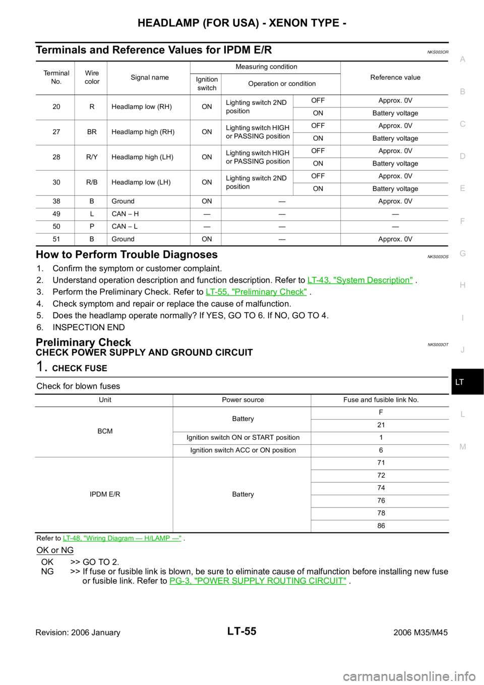
Terminals and Reference Values for IPDM E/RNKS003OR
How to Perform Trouble DiagnosesNKS003OS
1. Confirm the symptom or customer complaint.
2. Understand operation description and function description. Refer to LT- 4 3 , "
System Description" .
3. Perform the Preliminary Check. Refer to LT-55, "
Preliminary Check" .
4. Check symptom and repair or replace the cause of malfunction.
5. Does the headlamp operate normally? If YES, GO TO 6. If NO, GO TO 4.
6. INSPECTION END
Preliminary CheckNKS003OT
CHECK POWER SUPPLY AND GROUND CIRCUIT
1. CHECK FUSE
Check for blown fuses
Refer to LT-48, "Wiring Diagram — H/LAMP —" .
OK or NG
OK >> GO TO 2.
NG >> If fuse or fusible link is blown, be sure to eliminate cause of malfunction before installing new fuse
or fusible link. Refer to PG-3, "
POWER SUPPLY ROUTING CIRCUIT" .
Terminal
No.Wire
colorSignal nameMeasuring condition
Reference value
Ignition
switchOperation or condition
20 R Headlamp low (RH) ONLighting switch 2ND
positionOFF Approx. 0V
ON Battery voltage
27 BR Headlamp high (RH) ONLighting switch HIGH
or PASSING positionOFF Approx. 0V
ON Battery voltage
28 R/Y Headlamp high (LH) ONLighting switch HIGH
or PASSING positionOFF Approx. 0V
ON Battery voltage
30 R/B Headlamp low (LH) ONLighting switch 2ND
positionOFF Approx. 0V
ON Battery voltage
38 B Ground ON — Approx. 0V
49 L CAN
H — — —
50 P CAN
L — — —
51 B Ground ON — Approx. 0V
Unit Power source Fuse and fusible link No.
BCMBatteryF
21
Ignition switch ON or START position 1
Ignition switch ACC or ON position 6
IPDM E/R Battery71
72
74
76
78
86