Page 4533 of 5621
LT-106
HEADLAMP (FOR CANADA) - DAYTIME LIGHT SYSTEM -
Revision: 2006 January2006 M35/M45
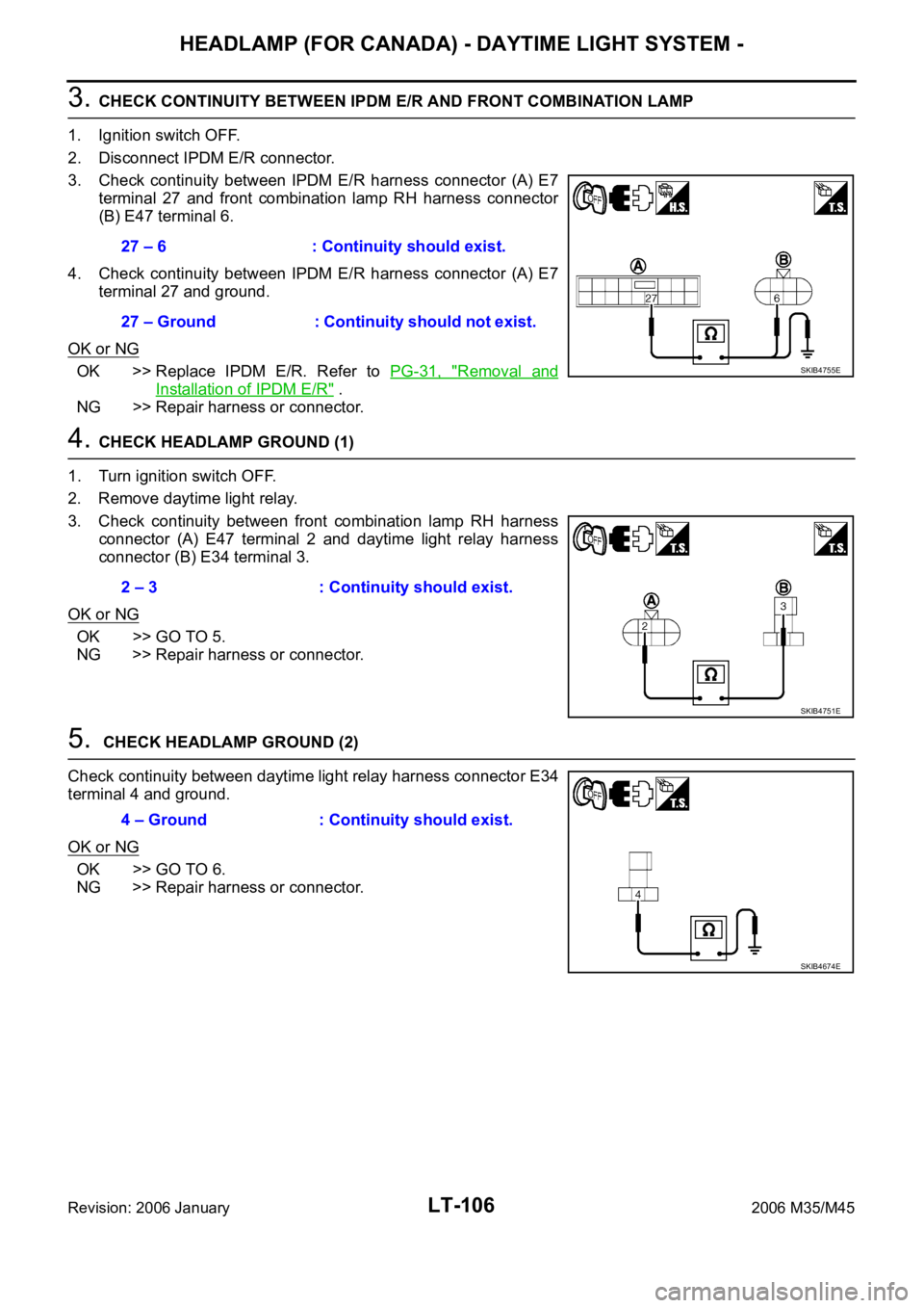
3. CHECK CONTINUITY BETWEEN IPDM E/R AND FRONT COMBINATION LAMP
1. Ignition switch OFF.
2. Disconnect IPDM E/R connector.
3. Check continuity between IPDM E/R harness connector (A) E7
terminal 27 and front combination lamp RH harness connector
(B) E47 terminal 6.
4. Check continuity between IPDM E/R harness connector (A) E7
terminal 27 and ground.
OK or NG
OK >> Replace IPDM E/R. Refer to PG-31, "Removal and
Installation of IPDM E/R" .
NG >> Repair harness or connector.
4. CHECK HEADLAMP GROUND (1)
1. Turn ignition switch OFF.
2. Remove daytime light relay.
3. Check continuity between front combination lamp RH harness
connector (A) E47 terminal 2 and daytime light relay harness
connector (B) E34 terminal 3.
OK or NG
OK >> GO TO 5.
NG >> Repair harness or connector.
5. CHECK HEADLAMP GROUND (2)
Check continuity between daytime light relay harness connector E34
terminal 4 and ground.
OK or NG
OK >> GO TO 6.
NG >> Repair harness or connector.27 – 6 : Continuity should exist.
27 – Ground : Continuity should not exist.
SKIB4755E
2 – 3 : Continuity should exist.
SKIB4751E
4 – Ground : Continuity should exist.
SKIB4674E
Page 4535 of 5621
LT-108
HEADLAMP (FOR CANADA) - DAYTIME LIGHT SYSTEM -
Revision: 2006 January2006 M35/M45
3. CHECK HEADLAMP GROUND
1. Turn ignition switch OFF.
2. Check continuity headlamp harness connector E54 terminal 2
and ground.
OK or NG
OK >> Check connecting condition front headlamp LH connec-
tor harness.
NG >> Repair harness or connector.
4. CHECK CIRCUIT BETWEEN IPDM E/R AND FRONT COMBINATION LAMP
1. Turn ignition switch OFF.
2. Disconnect IPDM E/R connector and front combination lamp LH connector.
3. Check continuity between IPDM E/R harness connector (A) E7
terminal 28 and front combination lamp LH harness connector
(B) E54 terminal 6.
4. Check continuity between IPDM E/R harness connector (A) E7
terminal 28 and ground.
OK or NG
OK >> Replace IPDM E/R. Refer to PG-31, "Removal and
Installation of IPDM E/R" .
NG >> Repair harness or connector.2 – Ground : Continuity should exist.
SKIB4750E
28 – 6 : Continuity should exist.
28 – Ground : Continuity should not exist.
SKIB4757E
Page 4536 of 5621
HEADLAMP (FOR CANADA) - DAYTIME LIGHT SYSTEM -
LT-109
C
D
E
F
G
H
I
J
L
MA
B
LT
Revision: 2006 January2006 M35/M45
Headlamp Low Beam Does Not Illuminate (Both Sides)NKS003PO
1. CHECK COMBINATION SWITCH INPUT SIGNAL
With CONSULT-II
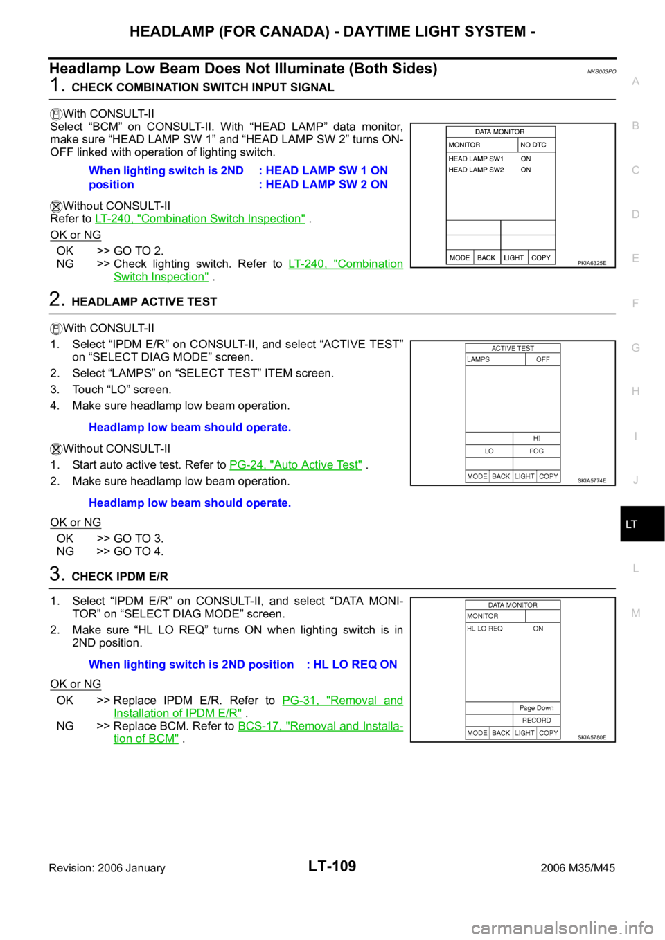
Select “BCM” on CONSULT-II. With “HEAD LAMP” data monitor,
make sure “HEAD LAMP SW 1” and “HEAD LAMP SW 2” turns ON-
OFF linked with operation of lighting switch.
Without CONSULT-II
Refer to LT-240, "
Combination Switch Inspection" .
OK or NG
OK >> GO TO 2.
NG >> Check lighting switch. Refer to LT- 2 4 0 , "
Combination
Switch Inspection" .
2. HEADLAMP ACTIVE TEST
With CONSULT-II
1. Select “IPDM E/R” on CONSULT-II, and select “ACTIVE TEST”
on “SELECT DIAG MODE” screen.
2. Select “LAMPS” on “SELECT TEST” ITEM screen.
3. Touch “LO” screen.
4. Make sure headlamp low beam operation.
Without CONSULT-II
1. Start auto active test. Refer to PG-24, "
Auto Active Test" .
2. Make sure headlamp low beam operation.
OK or NG
OK >> GO TO 3.
NG >> GO TO 4.
3. CHECK IPDM E/R
1. Select “IPDM E/R” on CONSULT-II, and select “DATA MONI-
TOR” on “SELECT DIAG MODE” screen.
2. Make sure “HL LO REQ” turns ON when lighting switch is in
2ND position.
OK or NG
OK >> Replace IPDM E/R. Refer to PG-31, "Removal and
Installation of IPDM E/R" .
NG >> Replace BCM. Refer to BCS-17, "
Removal and Installa-
tion of BCM" . When lighting switch is 2ND
position: HEAD LAMP SW 1 ON
: HEAD LAMP SW 2 ON
PKIA6325E
Headlamp low beam should operate.
Headlamp low beam should operate.
SKIA5774E
When lighting switch is 2ND position : HL LO REQ ON
SKIA5780E
Page 4538 of 5621
HEADLAMP (FOR CANADA) - DAYTIME LIGHT SYSTEM -
LT-111
C
D
E
F
G
H
I
J
L
MA
B
LT
Revision: 2006 January2006 M35/M45
6. CHECK CIRCUIT BETWEEN IPDM E/R AND FRONT COMBINATION LAMP
1. Turn ignition switch OFF.
2. Disconnect IPDM E/R connector.
3. Check continuity between IPDM E/R harness connector (A) ter-
minal and front combination lamp (RH and LH) harness connec-
tor (B) terminal.
4. Check continuity between IPDM E/R harness connector (A) ter-
minal and ground.
OK or NG
OK >> Replace IPDM E/R. Refer to PG-31, "Removal and Installation of IPDM E/R" .
NG >> Repair harness or connector.
CircuitAB
Continuity
Connector Terminal Connector Terminal
RH
E720 E47 8
Ye s
LH 30 E54 8
A
GroundContinuity
Connector Terminal
RH
E720
No
LH 30
SKIB4760E
Page 4540 of 5621
HEADLAMP (FOR CANADA) - DAYTIME LIGHT SYSTEM -
LT-113
C
D
E
F
G
H
I
J
L
MA
B
LT
Revision: 2006 January2006 M35/M45
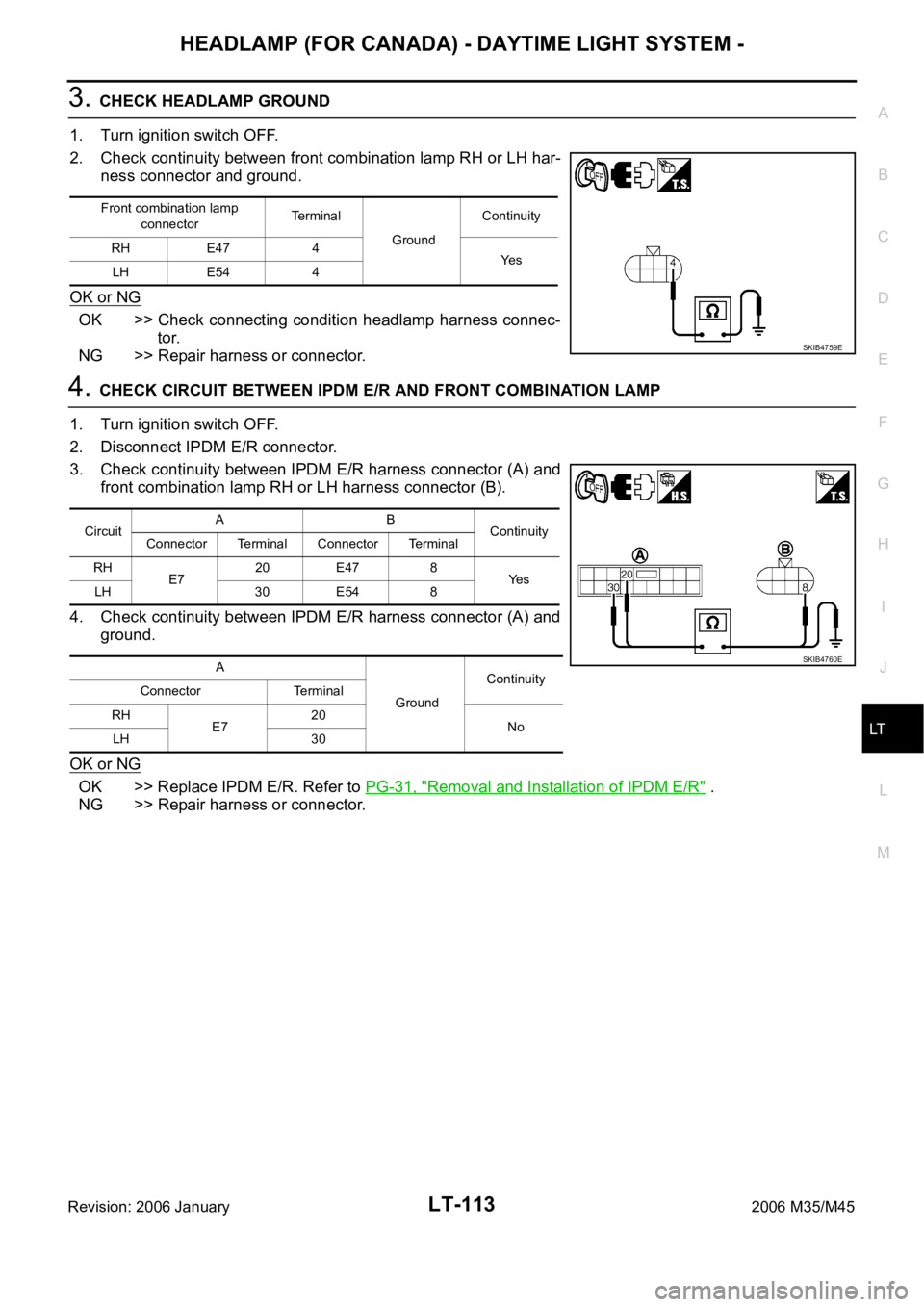
3. CHECK HEADLAMP GROUND
1. Turn ignition switch OFF.
2. Check continuity between front combination lamp RH or LH har-
ness connector and ground.
OK or NG
OK >> Check connecting condition headlamp harness connec-
tor.
NG >> Repair harness or connector.
4. CHECK CIRCUIT BETWEEN IPDM E/R AND FRONT COMBINATION LAMP
1. Turn ignition switch OFF.
2. Disconnect IPDM E/R connector.
3. Check continuity between IPDM E/R harness connector (A) and
front combination lamp RH or LH harness connector (B).
4. Check continuity between IPDM E/R harness connector (A) and
ground.
OK or NG
OK >> Replace IPDM E/R. Refer to PG-31, "Removal and Installation of IPDM E/R" .
NG >> Repair harness or connector.
Front combination lamp
connectorTe r m i n a l
GroundContinuity
RH E47 4
Ye s
LH E54 4
SKIB4759E
CircuitAB
Continuity
Connector Terminal Connector Terminal
RH
E720 E47 8
Ye s
LH 30 E54 8
A
GroundContinuity
Connector Terminal
RH
E720
No
LH 30
SKIB4760E
Page 4541 of 5621
LT-114
HEADLAMP (FOR CANADA) - DAYTIME LIGHT SYSTEM -
Revision: 2006 January2006 M35/M45
Headlamps Do Not Turn OFFNKS003PQ
1. CHECK HEADLAMP TURN OFF
Make sure that lighting switch is OFF. And make sure is headlamp turns off when ignition switch is turned OFF.
OK or NG
OK >> GO TO 3.
NG >> GO TO 2.
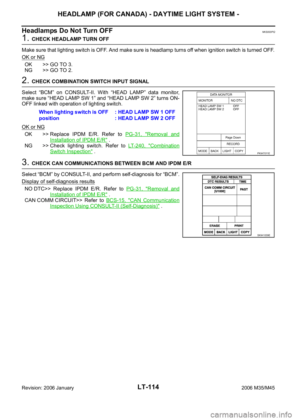
2. CHECK COMBINATION SWITCH INPUT SIGNAL
Select “BCM” on CONSULT-II. With “HEAD LAMP” data monitor,
make sure “HEAD LAMP SW 1” and “HEAD LAMP SW 2” turns ON-
OFF linked with operation of lighting switch.
OK or NG
OK >> Replace IPDM E/R. Refer to PG-31, "Removal and
Installation of IPDM E/R" .
NG >> Check lighting switch. Refer to LT- 2 4 0 , "
Combination
Switch Inspection" .
3. CHECK CAN COMMUNICATIONS BETWEEN BCM AND IPDM E/R
Select “BCM” by CONSULT-II, and perform self-diagnosis for “BCM”.
Display of self-diagnosis results
NO DTC>> Replace IPDM E/R. Refer to PG-31, "Removal and
Installation of IPDM E/R" .
CAN COMM CIRCUIT>> Refer to BCS-15, "
CAN Communication
Inspection Using CONSULT-II (Self-Diagnosis)" . When lighting switch is OFF
position: HEAD LAMP SW 1 OFF
: HEAD LAMP SW 2 OFF
PKIA7011E
SKIA1039E
Page 4542 of 5621

HEADLAMP (FOR CANADA) - DAYTIME LIGHT SYSTEM -
LT-115
C
D
E
F
G
H
I
J
L
MA
B
LT
Revision: 2006 January2006 M35/M45
General Information for Xenon Headlamp Trouble DiagnosisNKS003PR
In most cases, malfunction of xenon headlamp - "does not illuminate", "flickers" or "dark" - is caused by a mal-
functioning xenon bulb. A HID control unit or lamp housing, however, may be a cause of malfunction. Be sure
to perform trouble diagnosis following the steps described below.
CAUTION:NKS003PS
Installation or removal of connector must be done with lighting switch OFF.
When lamp is illuminated (when lighting switch is ON), do not touch harness, HID control unit, inside of
lamp, or lamp metal parts.
To check illumination, temporarily install lamp in the vehicle. Be sure to connect power at the vehicle-side
connector.
If the error can be traced directly to the electrical system, first check for items such as burned-out fuses
and fusible links, broken wires or loose connectors, pulled-out terminals, and improper connections.
Do not work with wet hands.
Using a tester for HID control unit circuit trouble diagnosis is prohibited.
Disassembling the HID control unit or harnesses (bulb socket harness, ECM harness) is prohibited.
Immediately after illumination, the light intensity and color will fluctuate, but there is nothing wrong.
When the bulb has reached the end of its lifetime, the brightness may drop significantly, it may flash
repeatedly, or the light may turn a reddish color.
Xenon Headlamp Trouble DiagnosisNKS003PT
1. CHECK 1: XENON HEADLAMP LIGHTING
Install normal xenon bulb to corresponding xenon bulb headlamp, and check if lamp lights up.
OK or NG
OK >> Replace xenon bulb.
NG >> GO TO 2.
2. CHECK 2: XENON HEADLAMP LIGHTING
Install normal HID control unit to corresponding xenon headlamp, and check if lamp lights up.
OK or NG
OK >> Replace HID control unit.
NG >> GO TO 3.
3. CHECK 3: XENON HEADLAMP LIGHTING
Install normal xenon lamp housing assembly to corresponding xenon headlamp, and check if lamp lights up.
OK or NG
OK >> Replace xenon headlamp housing assembly. [Malfunction in starter (boosting circuit) in xenon
headlamp housing]
NG >> INSPECTION END
Aiming AdjustmentNKS003PU
Refer to LT- 7 4 , "Aiming Adjustment" .
Bulb ReplacementNKS003PV
Refer to LT- 7 5 , "Bulb Replacement" .
Removal and InstallationNKS003PW
Refer to LT- 4 1 , "Removal and Installation" .
Disassembly and AssemblyNKS003PX
Refer to LT- 7 7 , "Disassembly and Assembly" .
Page 4553 of 5621
LT-126
AUTO LIGHT SYSTEM
Revision: 2006 January2006 M35/M45
Preliminary CheckNKS003Q8
SETTING CHANGE FUNCTIONS
Sensitivity of auto light system can be adjusted using CONSULT-II. Refer to LT-128, "WORK SUPPORT" .
CHECK POWER SUPPLY AND GROUND CIRCUIT
1. CHECK FUSE AND FUSIBLE LINK
Check for blown fuses.
Refer to LT-119, "Wiring Diagram — AUTO/L —" .
OK or NG
OK >> GO TO 2.
NG >> If fuse or fusible link is blown, be sure to eliminate cause of malfunction before installing new fuse
or fusible link. Refer to PG-3, "
POWER SUPPLY ROUTING CIRCUIT" .
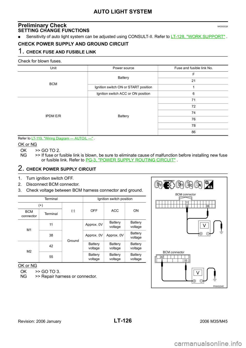
2. CHECK POWER SUPPLY CIRCUIT
1. Turn ignition switch OFF.
2. Disconnect BCM connector.
3. Check voltage between BCM harness connector and ground.
OK or NG
OK >> GO TO 3.
NG >> Repair harness or connector.
Unit Power source Fuse and fusible link No.
BCMBatteryF
21
Ignition switch ON or START position 1
Ignition switch ACC or ON position 6
IPDM E/R Battery71
72
74
76
78
86
Terminal Ignition switch position
(+)
(-) OFF ACC ON
BCM
connectorTerminal
M111
GroundApprox. 0VBattery
voltageBattery
voltage
38 Approx. 0V Approx. 0VBattery
voltage
M242Battery
voltageBattery
voltageBattery
voltage
55Battery
voltageBattery
voltageBattery
voltage
PKIA5204E