2006 INFINITI M35 stall
[x] Cancel search: stallPage 4560 of 5621
AUTO LIGHT SYSTEM
LT-133
C
D
E
F
G
H
I
J
L
MA
B
LT
Revision: 2006 January2006 M35/M45
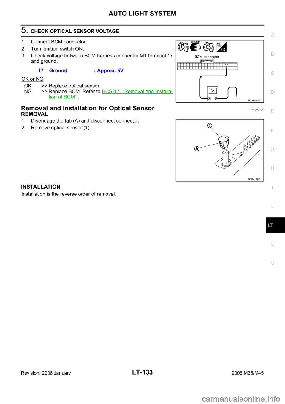
5. CHECK OPTICAL SENSOR VOLTAGE
1. Connect BCM connector.
2. Turn ignition switch ON.
3. Check voltage between BCM harness connector M1 terminal 17
and ground.
OK or NG
OK >> Replace optical sensor.
NG >> Replace BCM. Refer to BCS-17, "
Removal and Installa-
tion of BCM" .
Removal and Installation for Optical SensorNKS003QD
REMOVAL
1. Disengage the tab (A) and disconnect connector.
2. Remove optical sensor (1).
INSTALLATION
Installation is the reverse order of removal.17 – Ground : Approx. 5V
SKIA5894E
SKIB4159E
Page 4567 of 5621
LT-140
ACTIVE AFS
Revision: 2006 January2006 M35/M45
Component Parts DescriptionNKS003QG
AFS CONTROL UNIT
AFS control unit determines current vehicle conditions by received signals and controls AFS and headlamp
auto aiming.
SWIVEL ACTUATOR
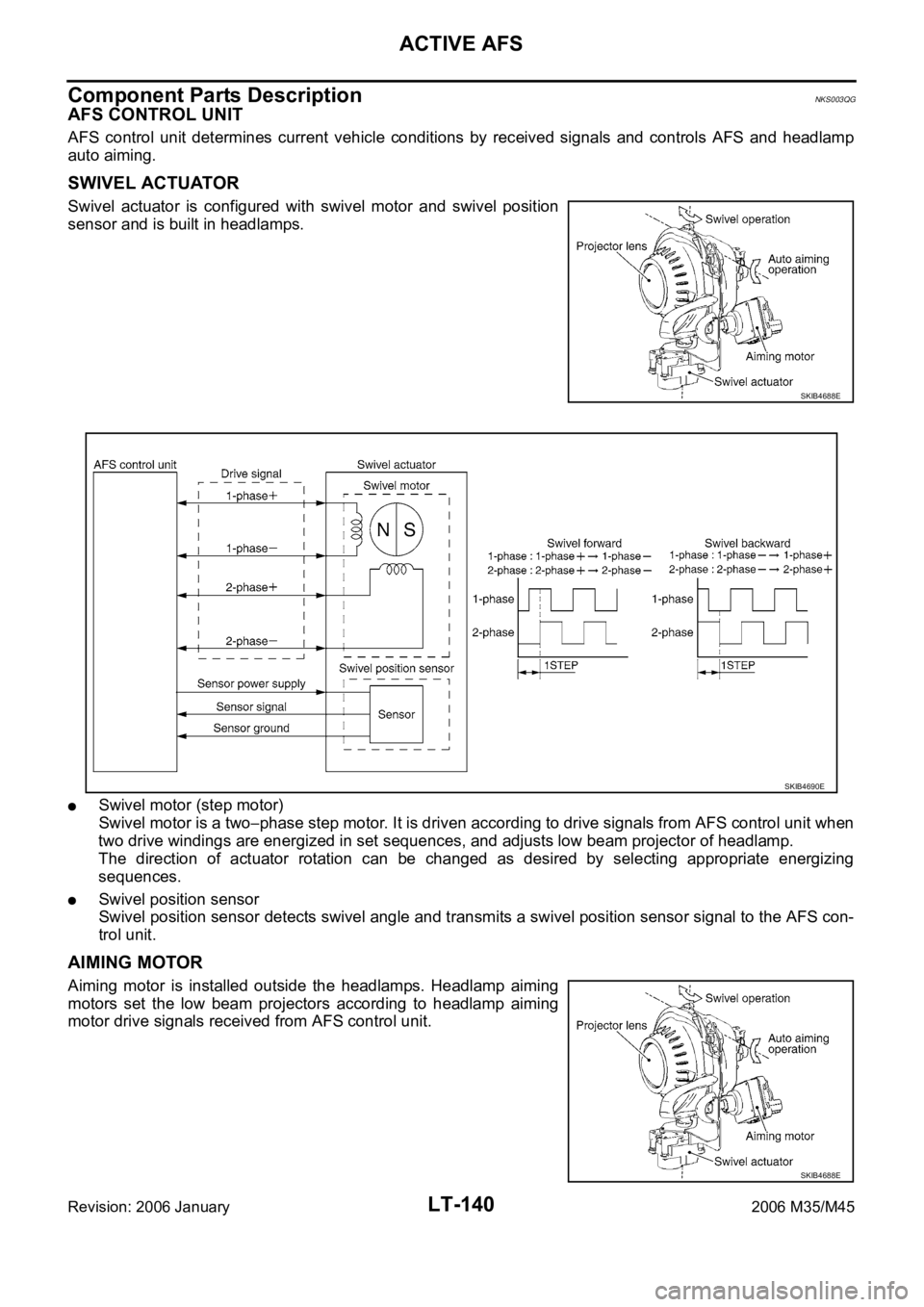
Swivel actuator is configured with swivel motor and swivel position
sensor and is built in headlamps.
Swivel motor (step motor)
Swivel motor is a two
phase step motor. It is driven according to drive signals from AFS control unit when
two drive windings are energized in set sequences, and adjusts low beam projector of headlamp.
The direction of actuator rotation can be changed as desired by selecting appropriate energizing
sequences.
Swivel position sensor
Swivel position sensor detects swivel angle and transmits a swivel position sensor signal to the AFS con-
trol unit.
AIMING MOTOR
Aiming motor is installed outside the headlamps. Headlamp aiming
motors set the low beam projectors according to headlamp aiming
motor drive signals received from AFS control unit.
SKIB4688E
SKIB4690E
SKIB4688E
Page 4578 of 5621
ACTIVE AFS
LT-151
C
D
E
F
G
H
I
J
L
MA
B
LT
Revision: 2006 January2006 M35/M45
How to Proceed with Trouble DiagnosisNKS003QK
1. Confirm the symptom or customer complaint.
2. Understand operation description and function description. Refer to LT-135, "
System Description" .
3. Perform the preliminary check. Refer to LT- 1 5 1 , "
Preliminary Check" .
4. Perform self-diagnosis by CONSULT-II. Refer to LT-154, "
SELF-DIAG RESULTS" .
5. Check symptom and repair or replace the cause of malfunction.
6. Does the swivel control operate normally? If YES: GO TO 7. If NO: GO TO 4.
7. INSPECTION END
Preliminary CheckNKS003QL
1. CHECK FUSE
Check for blown fuses.
Refer to LT-143, "Wiring Diagram — AFS —" .
OK or NG
OK >> GO TO 2.
NG >> If the fuse is brown be sure to eliminate cause of malfunction before installing new fuse. Refer to
PG-3, "
POWER SUPPLY ROUTING CIRCUIT" .
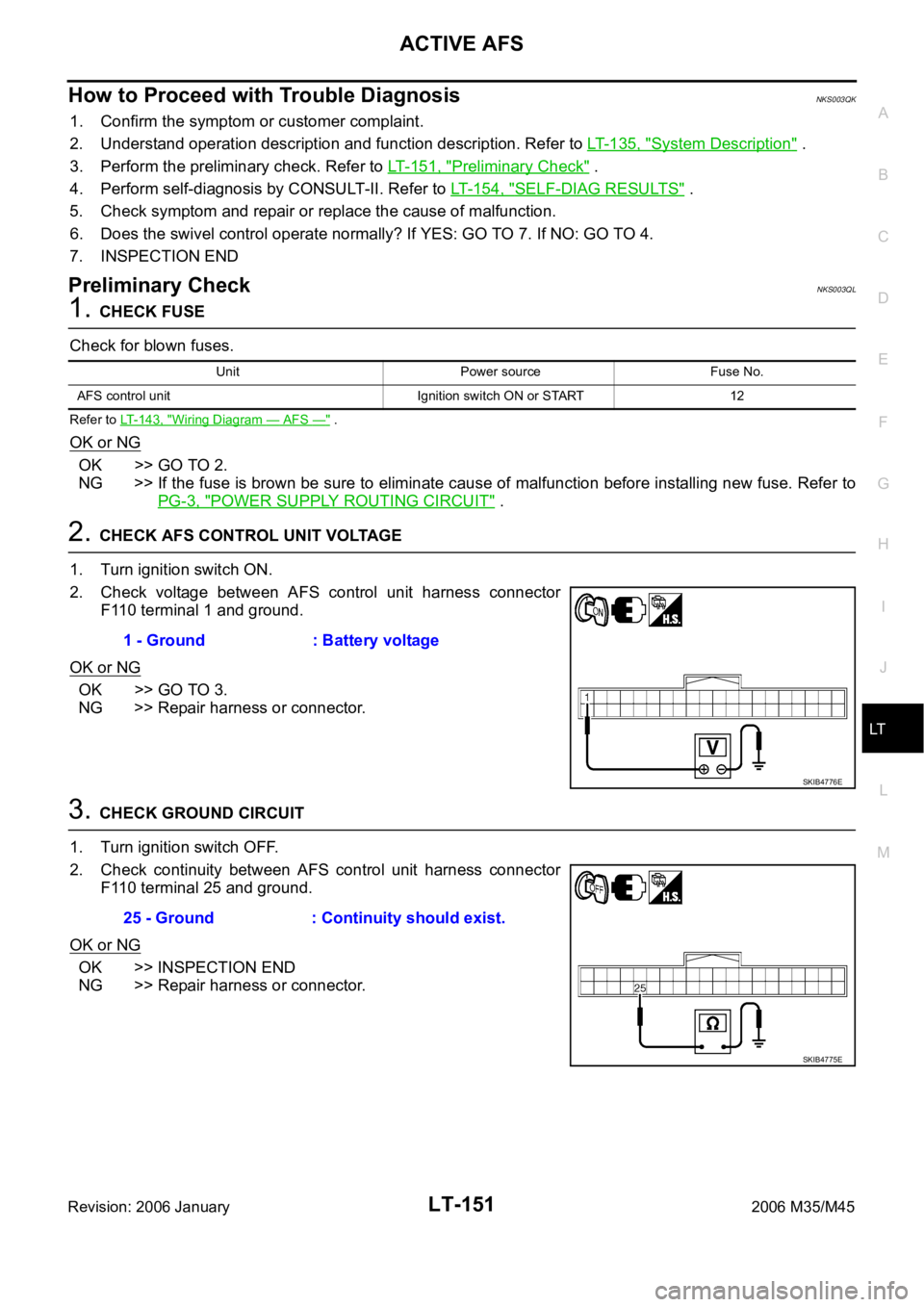
2. CHECK AFS CONTROL UNIT VOLTAGE
1. Turn ignition switch ON.
2. Check voltage between AFS control unit harness connector
F110 terminal 1 and ground.
OK or NG
OK >> GO TO 3.
NG >> Repair harness or connector.
3. CHECK GROUND CIRCUIT
1. Turn ignition switch OFF.
2. Check continuity between AFS control unit harness connector
F110 terminal 25 and ground.
OK or NG
OK >> INSPECTION END
NG >> Repair harness or connector.
Unit Power source Fuse No.
AFS control unit Ignition switch ON or START 12
1 - Ground : Battery voltage
SKIB4776E
25 - Ground : Continuity should exist.
SKIB4775E
Page 4580 of 5621
ACTIVE AFS
LT-153
C
D
E
F
G
H
I
J
L
MA
B
LT
Revision: 2006 January2006 M35/M45
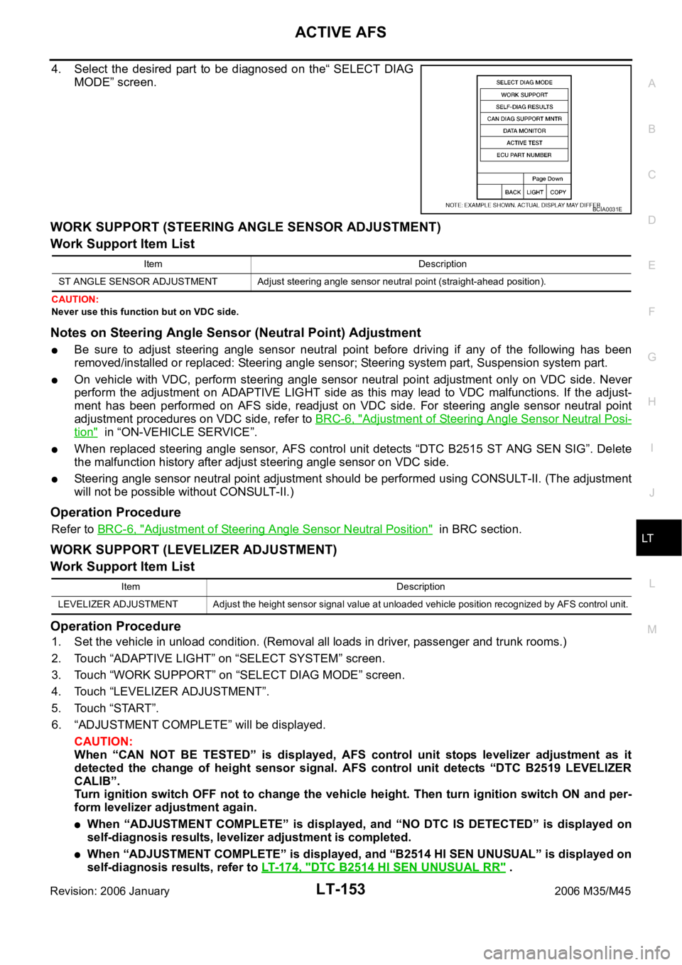
4. Select the desired part to be diagnosed on the“ SELECT DIAG
MODE” screen.
WORK SUPPORT (STEERING ANGLE SENSOR ADJUSTMENT)
Work Support Item List
CAUTION:
Never use this function but on VDC side.
Notes on Steering Angle Sensor (Neutral Point) Adjustment
Be sure to adjust steering angle sensor neutral point before driving if any of the following has been
removed/installed or replaced: Steering angle sensor; Steering system part, Suspension system part.
On vehicle with VDC, perform steering angle sensor neutral point adjustment only on VDC side. Never
perform the adjustment on ADAPTIVE LIGHT side as this may lead to VDC malfunctions. If the adjust-
ment has been performed on AFS side, readjust on VDC side. For steering angle sensor neutral point
adjustment procedures on VDC side, refer to BRC-6, "
Adjustment of Steering Angle Sensor Neutral Posi-
tion" in “ON-VEHICLE SERVICE”.
When replaced steering angle sensor, AFS control unit detects “DTC B2515 ST ANG SEN SIG”. Delete
the malfunction history after adjust steering angle sensor on VDC side.
Steering angle sensor neutral point adjustment should be performed using CONSULT-II. (The adjustment
will not be possible without CONSULT-II.)
Operation Procedure
Refer to BRC-6, "Adjustment of Steering Angle Sensor Neutral Position" in BRC section.
WORK SUPPORT (LEVELIZER ADJUSTMENT)
Work Support Item List
Operation Procedure
1. Set the vehicle in unload condition. (Removal all loads in driver, passenger and trunk rooms.)
2. Touch “ADAPTIVE LIGHT” on “SELECT SYSTEM” screen.
3. Touch “WORK SUPPORT” on “SELECT DIAG MODE” screen.
4. Touch “LEVELIZER ADJUSTMENT”.
5. Touch “START”.
6. “ADJUSTMENT COMPLETE” will be displayed.
CAUTION:
When “CAN NOT BE TESTED” is displayed, AFS control unit stops levelizer adjustment as it
detected the change of height sensor signal. AFS control unit detects “DTC B2519 LEVELIZER
CALIB”.
Turn ignition switch OFF not to change the vehicle height. Then turn ignition switch ON and per-
form levelizer adjustment again.
When “ADJUSTMENT COMPLETE” is displayed, and “NO DTC IS DETECTED” is displayed on
self-diagnosis results, levelizer adjustment is completed.
When “ADJUSTMENT COMPLETE” is displayed, and “B2514 HI SEN UNUSUAL” is displayed on
self-diagnosis results, refer to LT-174, "
DTC B2514 HI SEN UNUSUAL RR" .
BCIA0031E
Item Description
ST ANGLE SENSOR ADJUSTMENT Adjust steering angle sensor neutral point (straight-ahead position).
Item Description
LEVELIZER ADJUSTMENT Adjust the height sensor signal value at unloaded vehicle position recognized by AFS control unit.
Page 4588 of 5621

ACTIVE AFS
LT-161
C
D
E
F
G
H
I
J
L
MA
B
LT
Revision: 2006 January2006 M35/M45
Symptom ChartNKS003QN
CAUTION:
The low beam headlamps performs small movements when AFS control unit detects the engine start.
This is normal with initialization of swivel actuator by AFS control unit.
SymptomAFS OFF
indicatorCausal system Reference
AFS operates, but cannot judge normal/
abnormal.
(AFS function test)NormalCheck swivel operation.LT-181, "AFS
Operation
Check (Func-
tion Test)"
Check steering angle sensor neutral point (straight-ahead
position).
Auto aiming operates, but cannot judge
normal/abnormal.
(Auto aiming function test)NormalCheck auto aiming operation.LT-183, "Auto
Aiming Opera-
tion Check
(Function
Te s t )"
Check height sensor signal value recognized by AFS con-
trol unit at unloaded vehicle position.
Check height sensor signal and aiming motor drive signal.
Neither AFS operates nor auto aiming
operates.BlinkingCheck AFS control unit self-diagnostic results. LT-154,
"SELF-DIAG
RESULTS"
Check AFS control unit power supply and ground circuit.
NOTE:
Check only when “ADAPTIVE LIGHT” is not displayed on
CONSULT-II “SELECT SYSTEM” screen.LT-151, "Pre-
liminary
Check"
AFS does not operate.
(Auto aiming operation is normal.)Blinking Check AFS control unit self-diagnostic results. LT-154,
"SELF-DIAG
RESULTS"
Illuminated Check AFS switch system circuit.LT-185, "
AFS
Switch Does
Not Operate"
Auto aiming does not operate.
(AFS operation is normal.)NormalCheck AFS control unit self-diagnostic results. LT-154,
"SELF-DIAG
RESULTS"
Check aiming motor system circuit.LT-187, "
Auto
Aiming Does
Not Operate
(Check Aiming
Motor System
Circuit)"
Auto aiming operates in the reverse way.
(Lowering vehicle height angles light
axis up.)Normal Replace AFS control unit.LT-191, "Removal and
Installation of
AFS Control
Unit"
AFS OFF indicator does not illuminate.
(AFS operation and auto aiming opera-
tion are normal.)Not
illuminatedCheck circuit between unified meter and A/C amp. and
combination meter.LT-190, "
AFS
OFF Indicator
Does Not
Operate"AFS OFF indicator blinks.
(AFS operation and auto aiming opera-
tion are normal.)BlinkingCheck receive state of AFS off indicator signal from uni-
fied meter and A/C amp.
AFS cannot be cancelled.
(AFS switch does not operate.)Normal Check AFS switch system circuit.LT-185, "AFS
Switch Does
Not Operate"
Page 4589 of 5621
LT-162
ACTIVE AFS
Revision: 2006 January2006 M35/M45
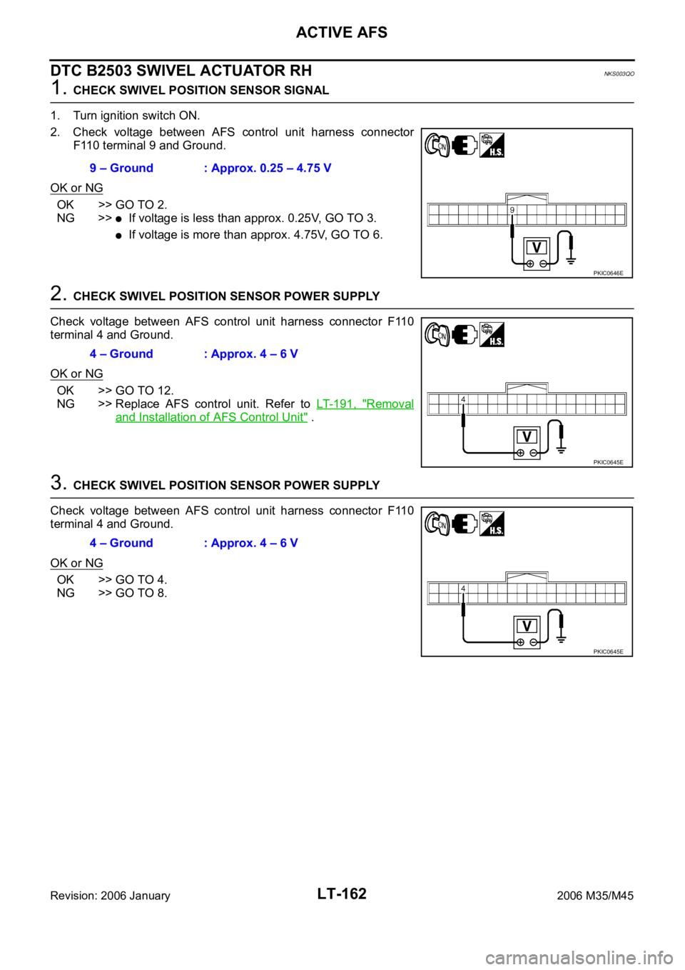
DTC B2503 SWIVEL ACTUATOR RHNKS003QO
1. CHECK SWIVEL POSITION SENSOR SIGNAL
1. Turn ignition switch ON.
2. Check voltage between AFS control unit harness connector
F110 terminal 9 and Ground.
OK or NG
OK >> GO TO 2.
NG >>
If voltage is less than approx. 0.25V, GO TO 3.
If voltage is more than approx. 4.75V, GO TO 6.
2. CHECK SWIVEL POSITION SENSOR POWER SUPPLY
Check voltage between AFS control unit harness connector F110
terminal 4 and Ground.
OK or NG
OK >> GO TO 12.
NG >> Replace AFS control unit. Refer to LT- 1 9 1 , "
Removal
and Installation of AFS Control Unit" .
3. CHECK SWIVEL POSITION SENSOR POWER SUPPLY
Check voltage between AFS control unit harness connector F110
terminal 4 and Ground.
OK or NG
OK >> GO TO 4.
NG >> GO TO 8.9 – Ground : Approx. 0.25 – 4.75 V
PKIC0646E
4 – Ground : Approx. 4 – 6 V
PKIC0645E
4 – Ground : Approx. 4 – 6 V
PKIC0645E
Page 4590 of 5621
ACTIVE AFS
LT-163
C
D
E
F
G
H
I
J
L
MA
B
LT
Revision: 2006 January2006 M35/M45
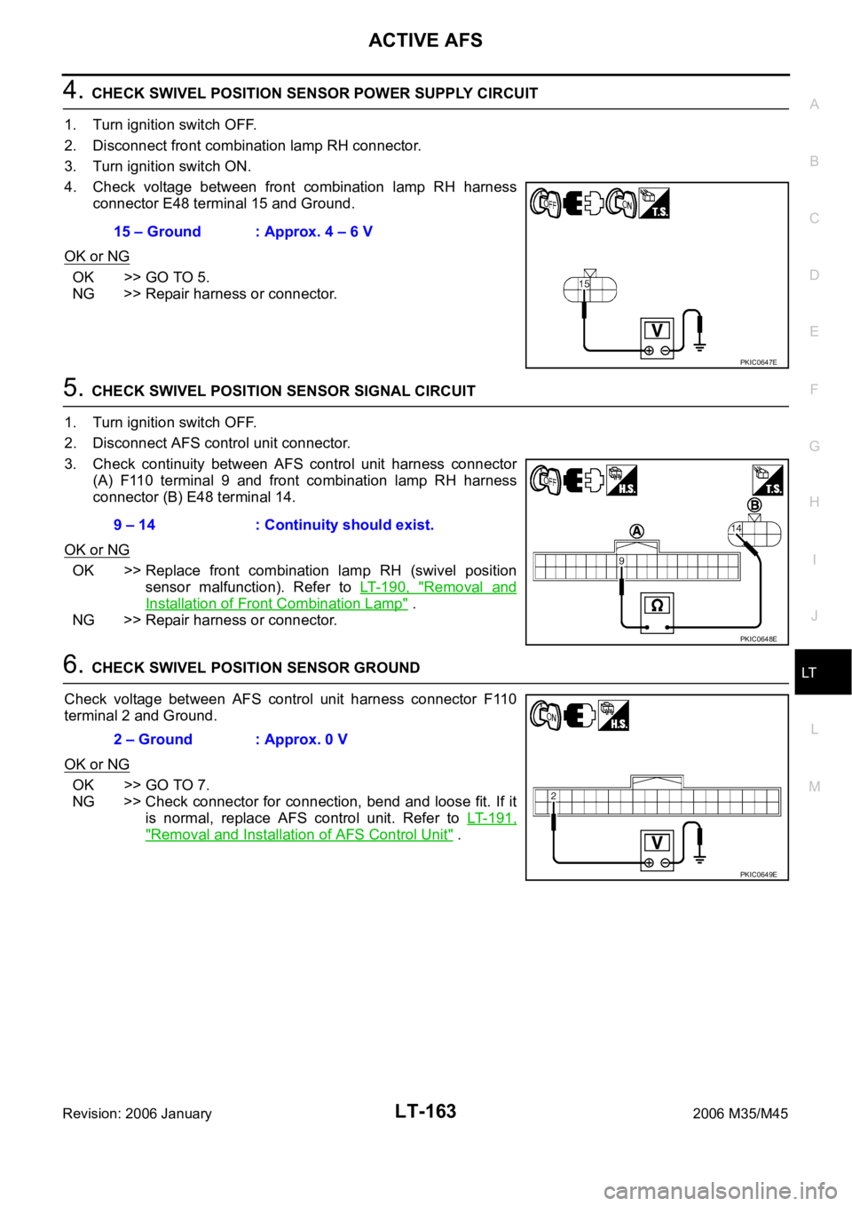
4. CHECK SWIVEL POSITION SENSOR POWER SUPPLY CIRCUIT
1. Turn ignition switch OFF.
2. Disconnect front combination lamp RH connector.
3. Turn ignition switch ON.
4. Check voltage between front combination lamp RH harness
connector E48 terminal 15 and Ground.
OK or NG
OK >> GO TO 5.
NG >> Repair harness or connector.
5. CHECK SWIVEL POSITION SENSOR SIGNAL CIRCUIT
1. Turn ignition switch OFF.
2. Disconnect AFS control unit connector.
3. Check continuity between AFS control unit harness connector
(A) F110 terminal 9 and front combination lamp RH harness
connector (B) E48 terminal 14.
OK or NG
OK >> Replace front combination lamp RH (swivel position
sensor malfunction). Refer to LT- 1 9 0 , "
Removal and
Installation of Front Combination Lamp" .
NG >> Repair harness or connector.
6. CHECK SWIVEL POSITION SENSOR GROUND
Check voltage between AFS control unit harness connector F110
terminal 2 and Ground.
OK or NG
OK >> GO TO 7.
NG >> Check connector for connection, bend and loose fit. If it
is normal, replace AFS control unit. Refer to LT- 1 9 1 ,
"Removal and Installation of AFS Control Unit" . 15 – Ground : Approx. 4 – 6 V
PKIC0647E
9 – 14 : Continuity should exist.
PKIC0648E
2 – Ground : Approx. 0 V
PKIC0649E
Page 4591 of 5621
LT-164
ACTIVE AFS
Revision: 2006 January2006 M35/M45
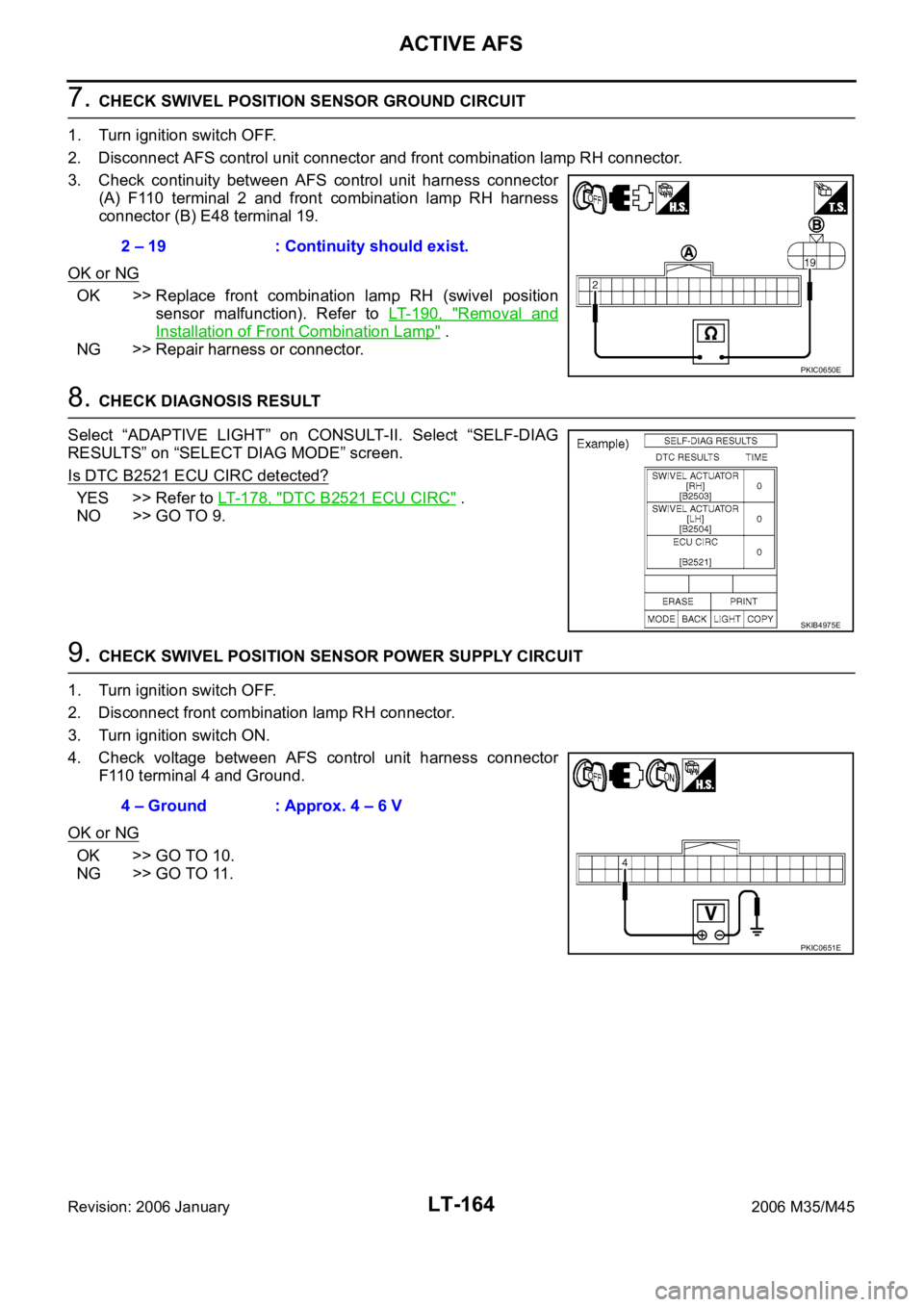
7. CHECK SWIVEL POSITION SENSOR GROUND CIRCUIT
1. Turn ignition switch OFF.
2. Disconnect AFS control unit connector and front combination lamp RH connector.
3. Check continuity between AFS control unit harness connector
(A) F110 terminal 2 and front combination lamp RH harness
connector (B) E48 terminal 19.
OK or NG
OK >> Replace front combination lamp RH (swivel position
sensor malfunction). Refer to LT- 1 9 0 , "
Removal and
Installation of Front Combination Lamp" .
NG >> Repair harness or connector.
8. CHECK DIAGNOSIS RESULT
Select “ADAPTIVE LIGHT” on CONSULT-II. Select “SELF-DIAG
RESULTS” on “SELECT DIAG MODE” screen.
Is DTC B2521 ECU CIRC detected?
YES >> Refer to LT- 1 7 8 , "DTC B2521 ECU CIRC" .
NO >> GO TO 9.
9. CHECK SWIVEL POSITION SENSOR POWER SUPPLY CIRCUIT
1. Turn ignition switch OFF.
2. Disconnect front combination lamp RH connector.
3. Turn ignition switch ON.
4. Check voltage between AFS control unit harness connector
F110 terminal 4 and Ground.
OK or NG
OK >> GO TO 10.
NG >> GO TO 11.2 – 19 : Continuity should exist.
PKIC0650E
SKIB4975E
4 – Ground : Approx. 4 – 6 V
PKIC0651E