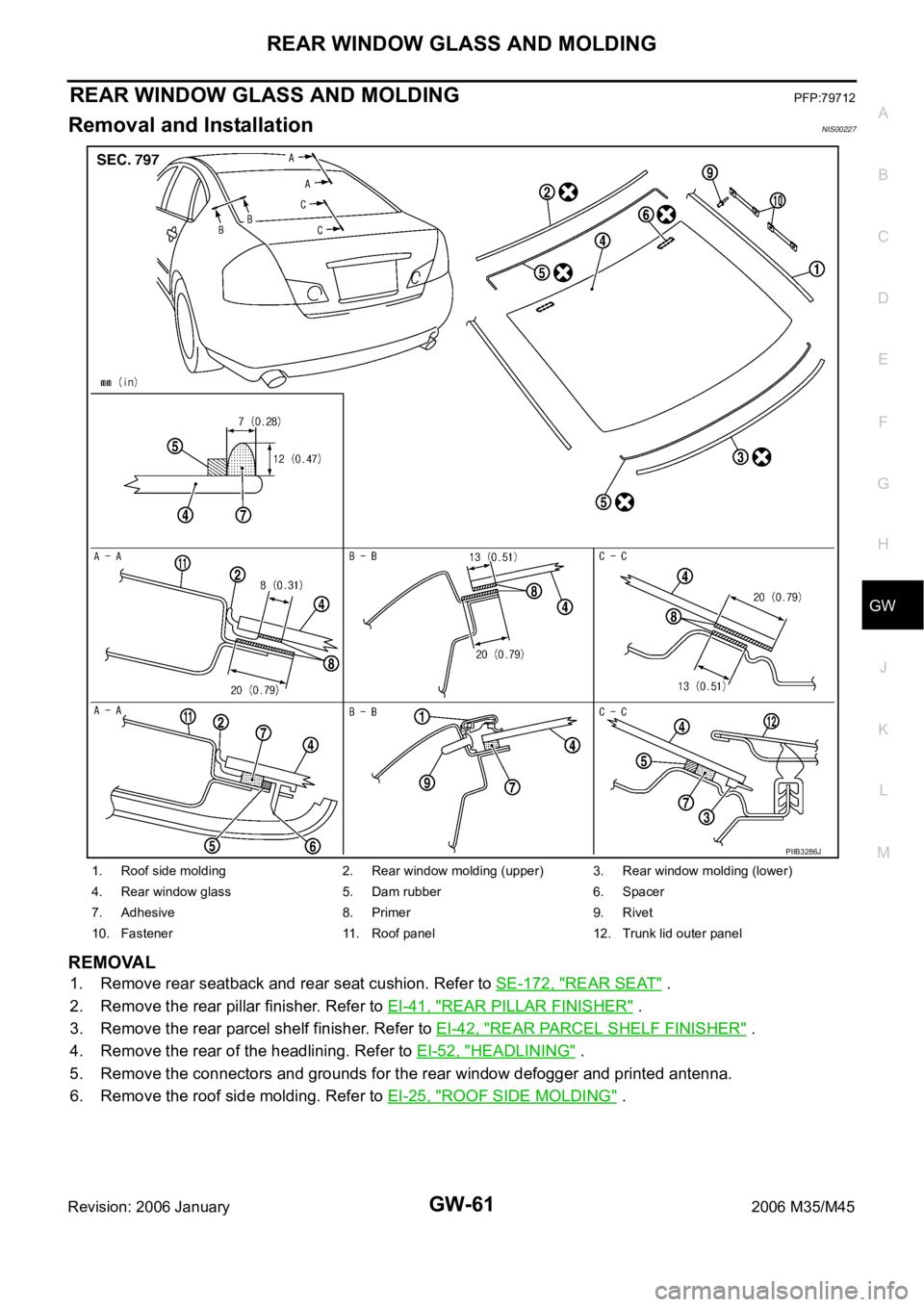
2006 INFINITI M35 trunk
[x] Cancel search: trunkPage 3527 of 5621

GW-8
SQUEAK AND RATTLE TROUBLE DIAGNOSES
Revision: 2006 January2006 M35/M45
TRUNK
Trunk noises are often caused by a loose jack or loose items put into the trunk by the owner.
In addition look for:
1. Trunk lid dumpers out of adjustment
2. Trunk lid striker out of adjustment
3. The trunk lid torsion bars knocking together
4. A loose license plate or bracket
Most of these incidents can be repaired by adjusting, securing or insulating the item(s) or component(s) caus-
ing the noise.
SUNROOF/HEADLINING
Noises in the sunroof/headlining area can often be traced to one of the following:
1. Sunroof lid, rail, linkage or seals making a rattle or light knocking noise
2. Sunvisor shaft shaking in the holder
3. Front or rear windshield touching headlining and squeaking
Again, pressing on the components to stop the noise while duplicating the conditions can isolate most of these
incidents. Repairs usually consist of insulating with felt cloth tape.
SEATS
When isolating seat noise it's important to note the position the seat is in and the load placed on the seat when
the noise is present. These conditions should be duplicated when verifying and isolating the cause of the
noise.
Cause of seat noise include:
1. Headrest rods and holder
2. A squeak between the seat pad cushion and frame
3. The rear seatback lock and bracket
These noises can be isolated by moving or pressing on the suspected components while duplicating the con-
ditions under which the noise occurs. Most of these incidents can be repaired by repositioning the component
or applying urethane tape to the contact area.
UNDERHOOD
Some interior noise may be caused by components under the hood or on the engine wall. The noise is then
transmitted into the passenger compartment.
Causes of transmitted underhood noise include:
1. Any component mounted to the engine wall
2. Components that pass through the engine wall
3. Engine wall mounts and connectors
4. Loose radiator mounting pins
5. Hood bumpers out of adjustment
6. Hood striker out of adjustment
These noises can be difficult to isolate since they cannot be reached from the interior of the vehicle. The best
method is to secure, move or insulate one component at a time and test drive the vehicle. Also, engine RPM
or load can be changed to isolate the noise. Repairs can usually be made by moving, adjusting, securing, or
insulating the component causing the noise.
Page 3580 of 5621

REAR WINDOW GLASS AND MOLDING
GW-61
C
D
E
F
G
H
J
K
L
MA
B
GW
Revision: 2006 January2006 M35/M45
REAR WINDOW GLASS AND MOLDINGPFP:79712
Removal and InstallationNIS00227
REMOVAL
1. Remove rear seatback and rear seat cushion. Refer to SE-172, "REAR SEAT" .
2. Remove the rear pillar finisher. Refer to EI-41, "
REAR PILLAR FINISHER" .
3. Remove the rear parcel shelf finisher. Refer to EI-42, "
REAR PARCEL SHELF FINISHER" .
4. Remove the rear of the headlining. Refer to EI-52, "
HEADLINING" .
5. Remove the connectors and grounds for the rear window defogger and printed antenna.
6. Remove the roof side molding. Refer to EI-25, "
ROOF SIDE MOLDING" .
1. Roof side molding 2. Rear window molding (upper) 3. Rear window molding (lower)
4. Rear window glass 5. Dam rubber 6. Spacer
7. Adhesive 8. Primer 9. Rivet
10. Fastener 11. Roof panel 12. Trunk lid outer panel
PIIB3286J
Page 3648 of 5621

IDX-7
A
C
D
E
F
G
H
I
J
K
L B
IDX
ALPHABETICAL INDEX
LT-266
Rear disc brake ................................................. BR-29
Rear door ............................................ BL-190, GW-67
Rear parcel shelf finisher ..................................... EI-42
Rear seat ......................................................... SE-172
Rear seat belt .................................................... SB-32
Rear suspension ............................................... RSU-5
Rear window ..................................................... GW-61
Rear window defogger ...................................... GW-73
Refrigerant connection precaution ..................... ATC-7
Refrigerant discharging evacuating charging ATC-151
Refrigerant general precaution .......................... ATC-7
Refrigerant lines ............................................ ATC-151
Refrigerant pressure sensor ........... EC-692, EC-1434,
ATC-98
, ATC-167
Refrigeration cycle ........................................... ATC-20
Removal and installation (A/T) ........... AT-271, AT-275
Removal and installation (Transfer) .................... TF-44
Reverse interlock door mirror ........................... GW-96
Revolution sensor (A/T) ...................... AT-119, AT-261
Rocker cover(VK45DE) ................................... EM-199
Rocker cover(VQ35DE) ..................................... EM-51
Room lamp - See Interior lamp ......................... LT-267
ROOM/L - Wiring diagram ................................ LT-274
RP/SEN - Wiring diagram ................ EC-693, EC-1435
S
SAE J1979 - Service $01 - 09 ............. EC-54
, EC-764
SEAT - Wiring diagram ...................................... SE-98
Seat belt inspection ........................................... SB-33
Seat belt, front ................................................... SB-30
Seat belt, rear .................................................... SB-32
Seat, rear ......................................................... SE-172
Self-diagnosis (Transfer) .................................... TF-22
SEN/PW - Wiring diagram ............... EC-500, EC-1219
SHIFT - Wiring diagram ................................... AT-230
Shift lock system .............................................. AT-229
Shock absorber (rear) ..................................... RSU-10
Side air bag (satellite) sensor .......................... SRS-46
Side curtain air bag .......................................... SRS-43
Side trim .............................................................. EI-37
SMJ (super multiple junction) .......................... PG-106
Spark plug replacement ..................................... MA-27
Spark plug replacement(VQ35DE) .................... MA-20
Spark plug(VK45DE) ....................................... EM-191
Spark plug(VQ35DE) ......................................... EM-43
Specification value ............................. EC-155, EC-868
Speedometer ........................................................ DI-5
Spiral cable ...................................................... SRS-40
SROOF - Wiring diagram .................................. RF-13
SRS - See Supplemental Restraint System ...... SRS-5
SRS - Wiring diagram ...................................... SRS-12
SRS Trouble diagnoses ..................................... SRS-8
Stabilizer bar (rear) ......................................... RSU-17
Stall test (A/T) .................................................... AT-53
Standardized relay ........................................... PG-109
START - Wiring diagram ................................... SC-11
Starter ................................................................ SC-10
Starting system .................................................. SC-10
Steering gear and linkage inspection ................ MA-36
Steering linkage ................................................. PS-18
Steering wheel and column ................... PS-10, PS-13
Steering wheel turning force .............................. PS-10
Stop lamp .......................................................... LT-243
Stop lamp switch .............................. EC-598, EC-1329
STSIG - Wiring diagram ................................... AT-109
Sun roof, electric ................................................ RF-10
Sunload sensor ............................. ATC-119, ATC-128
Sunroof .................................................. RF-25, RF-28
Sunshade ............................................................ EI-44
Supplemental Restraint System ....................... SRS-5
Supplemental restraint system - Wiring diagram ..........
SRS-12
Suspension ....................................................... MA-37
Symbols and abbreviations ...................... GI-11, GI-24
System readiness test (SRT) code ...... EC-60, EC-770
T
Tachometer ........................................................... DI-5
Tail lamp ........................................................... LT-249
TCM circuit diagram ........................................... AT-52
TCM inspection table ......................................... AT-89
Thermostat(VK45DE) ....................................... CO-55
Thermostat(VQ35DE) ....................................... CO-29
Three way catalyst function (Bank 1) EC-392, EC-1113
Three way catalyst function (Bank 2) EC-392, EC-1113
Three way catalyst precautions ............................ GI-6
Three way catalyst(VK45DE) .......................... EM-183
Throttle control motor ....................... EC-619, EC-1351
Throttle control motor relay .............. EC-607, EC-1338
Throttle position sensor (TPS) .......... EC-231, EC-354,
EC-533
, EC-535, EC-640, EC-954, EC-1077, EC-1259,
EC-1261
, EC-1372
Throttle valve closed position learning . EC-95, EC-806
Tie-rod ............................................................... PS-18
Timing chain(VK45DE) ................................... EM-203
Timing chain(VQ35DE) ..................................... EM-64
Tire rotation ....................................................... MA-35
TLID - Wiring diagram ...................................... BL-211
Top tether strap child restraint ........................... SB-37
Torque converter installation ............. AT-274, AT-277
Torque convertor clutch solenoid valve AT-126, AT-128
TPS1 - Wiring diagram .................... EC-356, EC-1079
TPS2 - Wiring diagram ...................... EC-233, EC-956
TPS3 - Wiring diagram .................... EC-642, EC-1374
Transfer control unit inspection table ................. TF-20
TRNSCV - Wiring diagram ............................... BL-281
Trouble diagnoses .............................................. GI-12
Trunk lid ........................................................... BL-203
Trunk lid opener - See Trunk lid ...................... BL-209
TURN - Wiring diagram .................................... LT-215
Turn signal lamp ............................................... LT-211
Two trip detection logic ........................ EC-54, EC-764
Tyre pressure monitoring system - trouble diagnoses ..
WT-13
Page 3650 of 5621

IP-1
INSTRUMENT PANEL
I BODY
CONTENTS
C
D
E
F
G
H
J
K
L
M
SECTION IP
A
B
IP
Revision: 2006 January2006 M35/M45
INSTRUMENT PANEL
PRECAUTIONS .......................................................... 2
Precautions for Supplemental Restraint System
(SRS) “AIR BAG” and “SEAT BELT PRE-TEN-
SIONER” .................................................................. 2
Precautions .............................................................. 2
PREPARATION ........................................................... 3
Special Service Tools ............................................... 3
Commercial Service Tools ........................................ 3
SQUEAK AND RATTLE TROUBLE DIAGNOSES ..... 4
Work Flow ................................................................ 4
CUSTOMER INTERVIEW ..................................... 4
DUPLICATE THE NOISE AND TEST DRIVE ....... 5
CHECK RELATED SERVICE BULLETINS ........... 5
LOCATE THE NOISE AND IDENTIFY THE
ROOT CAUSE ...................................................... 5
REPAIR THE CAUSE ........................................... 5
CONFIRM THE REPAIR ....................................... 6
Generic Squeak and Rattle Troubleshooting ........... 6
INSTRUMENT PANEL .......................................... 6
CENTER CONSOLE ............................................. 6
DOORS ................................................................. 6TRUNK .................................................................. 7
SUNROOF/HEADLINING ..................................... 7
SEATS ................................................................... 7
UNDERHOOD ....................................................... 7
Diagnostic Worksheet ............................................... 8
INSTRUMENT PANEL ASSEMBLY ......................... 10
Component Parts Drawing ..................................... 10
Removal and Installation of Instrument Panel & Pad ... 11
REMOVAL ........................................................
... 11
INSTALLATION ................................................... 14
Removal and Installation of Cluster Lid A ............... 15
REMOVAL ........................................................
... 15
INSTALLATION ................................................... 16
Removal and Installation of Cluster Lid C .............. 17
REMOVAL ........................................................
... 17
INSTALLATION ................................................... 18
Removal and Installation of Glove Box Assembly ... 18
REMOVAL ........................................................
... 18
INSTALLATION ................................................... 18
Disassembly and Assembly .................................... 19
CENTER CONSOLE ASSEMBLY ....................... 19
Page 3656 of 5621

SQUEAK AND RATTLE TROUBLE DIAGNOSES
IP-7
C
D
E
F
G
H
J
K
L
MA
B
IP
Revision: 2006 January2006 M35/M45
TRUNK
Trunk noises are often caused by a loose jack or loose items put into the trunk by the owner.
In addition look for:
1. Trunk lid dumpers out of adjustment
2. Trunk lid striker out of adjustment
3. The trunk lid torsion bars knocking together
4. A loose license plate or bracket
Most of these incidents can be repaired by adjusting, securing or insulating the item(s) or component(s) caus-
ing the noise.
SUNROOF/HEADLINING
Noises in the sunroof/headlining area can often be traced to one of the following:
1. Sunroof lid, rail, linkage or seals making a rattle or light knocking noise
2. Sunvisor shaft shaking in the holder
3. Front or rear windshield touching headlining and squeaking
Again, pressing on the components to stop the noise while duplicating the conditions can isolate most of these
incidents. Repairs usually consist of insulating with felt cloth tape.
SEATS
When isolating seat noise it's important to note the position the seat is in and the load placed on the seat when
the noise is present. These conditions should be duplicated when verifying and isolating the cause of the
noise.
Cause of seat noise include:
1. Headrest rods and holder
2. A squeak between the seat pad cushion and frame
3. The rear seatback lock and bracket
These noises can be isolated by moving or pressing on the suspected components while duplicating the con-
ditions under which the noise occurs. Most of these incidents can be repaired by repositioning the component
or applying urethane tape to the contact area.
UNDERHOOD
Some interior noise may be caused by components under the hood or on the engine wall. The noise is then
transmitted into the passenger compartment.
Causes of transmitted underhood noise include:
1. Any component mounted to the engine wall
2. Components that pass through the engine wall
3. Engine wall mounts and connectors
4. Loose radiator mounting pins
5. Hood bumpers out of adjustment
6. Hood striker out of adjustment
These noises can be difficult to isolate since they cannot be reached from the interior of the vehicle. The best
method is to secure, move or insulate one component at a time and test drive the vehicle. Also, engine RPM
or load can be changed to isolate the noise. Repairs can usually be made by moving, adjusting, securing, or
insulating the component causing the noise.
Page 3710 of 5621
![INFINITI M35 2006 Factory Service Manual CAN COMMUNICATION
LAN-41
[CAN]
C
D
E
F
G
H
I
J
L
MA
B
LAN
Revision: 2006 January2006 M35/M45
Blower fan motor switch signal R T
Buzzer output signalTR
TR
RT
Day time running light request signal T R
D INFINITI M35 2006 Factory Service Manual CAN COMMUNICATION
LAN-41
[CAN]
C
D
E
F
G
H
I
J
L
MA
B
LAN
Revision: 2006 January2006 M35/M45
Blower fan motor switch signal R T
Buzzer output signalTR
TR
RT
Day time running light request signal T R
D](/manual-img/42/57023/w960_57023-3709.png)
CAN COMMUNICATION
LAN-41
[CAN]
C
D
E
F
G
H
I
J
L
MA
B
LAN
Revision: 2006 January2006 M35/M45
Blower fan motor switch signal R T
Buzzer output signalTR
TR
RT
Day time running light request signal T R
Door lock/unlock status signal T R
Door switch signal T R R R R R
Door unlock signal T R
Front fog light request signal T R R
Front wiper request signal T R R
High beam request signal T R R
Ignition switch ON signal T R R
Ignition switch signal T R R
Key ID signal T R
Key switch signal T R
Low beam request signal T R
Position light request signal T R R
Rear window defogger switch signal T R
Sleep wake up signal T R R R R
Starter request signal T R
Theft warning horn request signal T R
Trunk switch signal T R R
Turn indicator signal T R R
Tire pressure data signal T R
Tire pressure signal T R R
Steering angle sensor signal R T R R
Door lock/unlock trunk open request signal R T
Hazard and horn request signal R T
Key warning signalTR
Meter display signalTR
RT
Panic alarm request signal R T
Power window open request signal R T
A/C evaporator temperature signal R TSignals
ECM
TCM
AFS control unit*1
BCM
LDW camera unit*2
Low tire pressure warning control unit
Steering angle sensor
Intelligent Key unit
Unified meter and A/C amp.
AV (NAVI) control unit
RAS control unit*3
Pre-crash seat belt control unit*4
Driver seat control unit
ABS actuator and electric unit (control unit)
ICC sensor integrated unit*5
IPDM E/R
Page 3714 of 5621
![INFINITI M35 2006 Factory Service Manual CAN COMMUNICATION
LAN-45
[CAN]
C
D
E
F
G
H
I
J
L
MA
B
LAN
Revision: 2006 January2006 M35/M45
ACC signal T R R
Blower fan motor switch signal R T
Buzzer output signalTR
TR
RT
Day time running light req INFINITI M35 2006 Factory Service Manual CAN COMMUNICATION
LAN-45
[CAN]
C
D
E
F
G
H
I
J
L
MA
B
LAN
Revision: 2006 January2006 M35/M45
ACC signal T R R
Blower fan motor switch signal R T
Buzzer output signalTR
TR
RT
Day time running light req](/manual-img/42/57023/w960_57023-3713.png)
CAN COMMUNICATION
LAN-45
[CAN]
C
D
E
F
G
H
I
J
L
MA
B
LAN
Revision: 2006 January2006 M35/M45
ACC signal T R R
Blower fan motor switch signal R T
Buzzer output signalTR
TR
RT
Day time running light request signal T R
Door lock/unlock status signal T R
Door switch signal T R R R R R
Door unlock signal T R
Front fog light request signal T R R
Front wiper request signal T R R
High beam request signal T R R
Ignition switch ON signal T R R
Ignition switch signal T R R
Key ID signal T R
Key switch signal T R
Low beam request signal T R
Position light request signal T R R
Rear window defogger switch signal T R
Sleep wake up signal T R R R R
Starter request signal T R
Theft warning horn request signal T R
Trunk switch signal T R R
Turn indicator signal T R R
Tire pressure data signal T R
Tire pressure signal T R R
Steering angle sensor signal R T R
Door lock/unlock trunk open request signal R T
Hazard and horn request signal R T
Key warning signalTR
Meter display signalTR
RT
Panic alarm request signal R T
Power window open request signal R TSignals
ECM
TCM
AWD control unit
AFS control unit*1
BCM
LDW camera unit*2
Low tire pressure warning control unit
Steering angle sensor
Intelligent Key unit
Unified meter and A/C amp.
AV (NAVI) control unit
Pre-crash seat belt control unit*3
Driver seat control unit
ABS actuator and electric unit (control unit)
ICC sensor integrated unit*4
IPDM E/R
Page 4431 of 5621

LT-4Revision: 2006 January2006 M35/M45 HAZARD SWITCH ..................................................231
Removal and Installation ......................................231
REMOVAL ........................................................
.231
COMBINATION SWITCH ........................................232
Wiring Diagram — COMBSW — ..........................232
Combination Switch Reading Function .................233
Terminals and Reference Values for BCM ............233
CONSULT-II Functions (BCM) ..............................238
CONSULT-II BASIC OPERATION .....................238
DATA MONITOR ................................................239
Combination Switch Inspection ............................240
Removal and Installation ......................................242
STOP LAMP ............................................................243
Wiring Diagram — STOP LAMP — ......................243
High-Mounted Stop Lamp .....................................245
BULB REPLACEMENT, REMOVAL AND
INSTALLATION ..................................................245
Stop Lamp ............................................................245
BULB REPLACEMENT .....................................245
BULB REPLACEMENT .....................................245
BACK-UP LAMP .....................................................246
Wiring Diagram — B/LAMP — .............................246
Bulb Replacement ...............................................
.247
Removal and Installation ......................................248
REMOVAL ........................................................
.248
INSTALLATION ..................................................248
PARKING, LICENSE PLATE AND TAIL LAMPS ....249
Component Parts and Harness Connector Location .249
System Description ...............................................249
OUTLINE ...........................................................249
OPERATION BY LIGHTING SWITCH ...............250
COMBINATION SWITCH READING FUNCTION .250
EXTERIOR LAMP BATTERY SAVER CONTROL .250
CAN Communication System Description ............250
CAN Communication Unit .....................................250
Schematic .............................................................251
Wiring Diagram — TAIL/L — ................................252
Terminals and Reference Values for BCM ............257
Terminals and Reference Values for IPDM E/R ....258
How to Perform Trouble Diagnoses ......................258
Preliminary Check ................................................258
CHECK POWER SUPPLY AND GROUND CIR-
CUIT ..................................................................258
CONSULT-II Functions (BCM) ..............................259
CONSULT-II Functions (IPDM E/R) ......................259
Parking, License Plate and Tail Lamps Do Not Illu-
minate ...................................................................260
Parking, License Plate and Tail Lamps Do Not Turn
OFF (After Approx. 10 Minutes) ...........................264
License Plate Lamp ..............................................265
BULB REPLACEMENT .....................................265
Removal and Installation ......................................265
REMOVAL ........................................................
.265
INSTALLATION ..................................................265
Front Parking (Clearance) Lamp ..........................265
BULB REPLACEMENT .....................................265
REMOVAL AND INSTALLATION .......................265
REAR COMBINATION LAMP .................................266
Bulb Replacement ...............................................
.266REAR TURN SIGNAL LAMP BULB, STOP/TAIL
LAMP BULB ...................................................... .266
Removal and Installation .......................................266
REMOVAL ..........................................................266
INSTALLATION ..................................................266
INTERIOR ROOM LAMP ........................................267
Component Parts and Harness Connector Location .267
System Description ...............................................267
ROOM LAMP TIMER BASIC OPERATION .......267
POWER SUPPLY AND GROUND .....................268
SWITCH OPERATION .......................................269
ROOM LAMP TIMER OPERATION ...................270
CONDITIONS FOR CANCELING TIMER ..........271
ROOM LAMP TIMER INAPPLICABLE LAMPS
OPERATION ......................................................271
INTERIOR ROOM LAMP BATTERY SAVER
FUNCTION .......................................................
.271
Schematic .............................................................272
Wiring Diagram — ROOM/L — .............................274
Terminals and Reference Values for BCM ............281
How to Perform Trouble Diagnoses ......................282
Preliminary Check .................................................283
CHECK POWER SUPPLY AND GROUND CIR-
CUIT ...................................................................283
CONSULT-II Functions (BCM) ..............................284
CONSULT-II BASIC OPERATION .....................284
WORK SUPPORT (INT LAMP) .........................285
DATA MONITOR (INT LAMP) ............................286
ACTIVE TEST (INT LAMP) ................................287
WORK SUPPORT (BATTERY SAVER) .............287
DATA MONITOR (BATTERY SAVER) ...............287
ACTIVE TEST (BATTERY SAVER) ...................288
Interior Room Lamp Control Does Not Operate ....289
Map Lamp .............................................................291
BULB REPLACEMENT ......................................291
REMOVAL AND INSTALLATION .......................291
Personal Lamp ......................................................291
BULB REPLACEMENT ......................................291
REMOVAL AND INSTALLATION .......................291
Foot Lamp (Driver Side) .......................................
.292
BULB REPLACEMENT ......................................292
REMOVAL AND INSTALLATION .......................292
Foot Lamp (Passenger Side) ................................293
BULB REPLACEMENT ......................................293
REMOVAL AND INSTALLATION .......................293
Vanity Mirror Lamp ................................................293
BULB REPLACEMENT ......................................293
Step Lamp .............................................................294
BULB REPLACEMENT ......................................294
REMOVAL AND INSTALLATION .......................294
Kicking Plate Illumination .....................................
.294
BULB REPLACEMENT ......................................294
REMOVAL AND INSTALLATION .......................294
Trunk Room Lamp (Upper/Lower) ........................294
BULB REPLACEMENT ......................................294
REMOVAL AND INSTALLATION .......................294
ILLUMINATION ........................................................295
System Description ...............................................295
OUTLINE ...........................................................295