2006 INFINITI M35 trunk
[x] Cancel search: trunkPage 4580 of 5621
ACTIVE AFS
LT-153
C
D
E
F
G
H
I
J
L
MA
B
LT
Revision: 2006 January2006 M35/M45
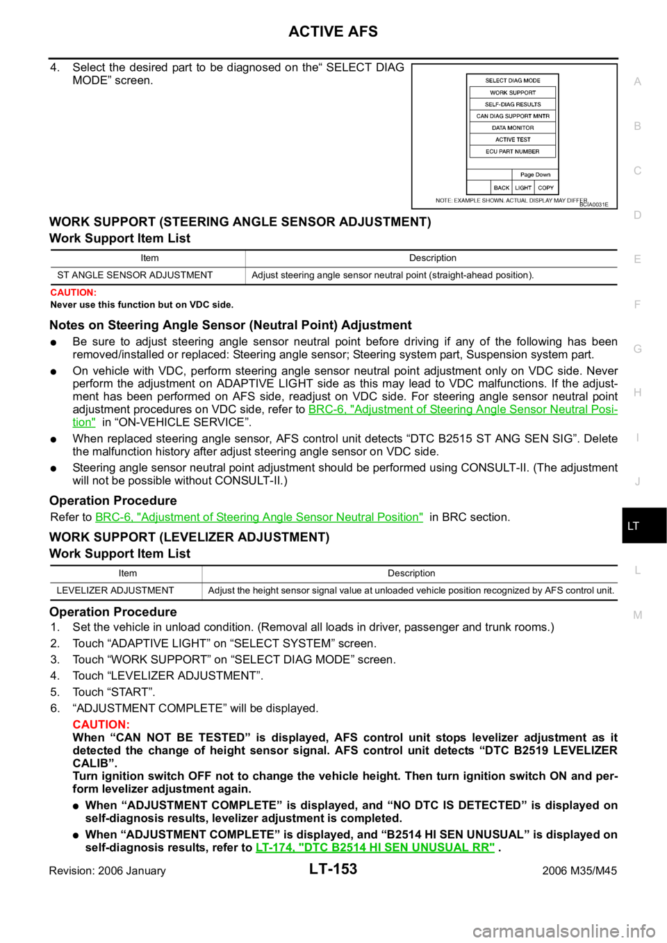
4. Select the desired part to be diagnosed on the“ SELECT DIAG
MODE” screen.
WORK SUPPORT (STEERING ANGLE SENSOR ADJUSTMENT)
Work Support Item List
CAUTION:
Never use this function but on VDC side.
Notes on Steering Angle Sensor (Neutral Point) Adjustment
Be sure to adjust steering angle sensor neutral point before driving if any of the following has been
removed/installed or replaced: Steering angle sensor; Steering system part, Suspension system part.
On vehicle with VDC, perform steering angle sensor neutral point adjustment only on VDC side. Never
perform the adjustment on ADAPTIVE LIGHT side as this may lead to VDC malfunctions. If the adjust-
ment has been performed on AFS side, readjust on VDC side. For steering angle sensor neutral point
adjustment procedures on VDC side, refer to BRC-6, "
Adjustment of Steering Angle Sensor Neutral Posi-
tion" in “ON-VEHICLE SERVICE”.
When replaced steering angle sensor, AFS control unit detects “DTC B2515 ST ANG SEN SIG”. Delete
the malfunction history after adjust steering angle sensor on VDC side.
Steering angle sensor neutral point adjustment should be performed using CONSULT-II. (The adjustment
will not be possible without CONSULT-II.)
Operation Procedure
Refer to BRC-6, "Adjustment of Steering Angle Sensor Neutral Position" in BRC section.
WORK SUPPORT (LEVELIZER ADJUSTMENT)
Work Support Item List
Operation Procedure
1. Set the vehicle in unload condition. (Removal all loads in driver, passenger and trunk rooms.)
2. Touch “ADAPTIVE LIGHT” on “SELECT SYSTEM” screen.
3. Touch “WORK SUPPORT” on “SELECT DIAG MODE” screen.
4. Touch “LEVELIZER ADJUSTMENT”.
5. Touch “START”.
6. “ADJUSTMENT COMPLETE” will be displayed.
CAUTION:
When “CAN NOT BE TESTED” is displayed, AFS control unit stops levelizer adjustment as it
detected the change of height sensor signal. AFS control unit detects “DTC B2519 LEVELIZER
CALIB”.
Turn ignition switch OFF not to change the vehicle height. Then turn ignition switch ON and per-
form levelizer adjustment again.
When “ADJUSTMENT COMPLETE” is displayed, and “NO DTC IS DETECTED” is displayed on
self-diagnosis results, levelizer adjustment is completed.
When “ADJUSTMENT COMPLETE” is displayed, and “B2514 HI SEN UNUSUAL” is displayed on
self-diagnosis results, refer to LT-174, "
DTC B2514 HI SEN UNUSUAL RR" .
BCIA0031E
Item Description
ST ANGLE SENSOR ADJUSTMENT Adjust steering angle sensor neutral point (straight-ahead position).
Item Description
LEVELIZER ADJUSTMENT Adjust the height sensor signal value at unloaded vehicle position recognized by AFS control unit.
Page 4610 of 5621

ACTIVE AFS
LT-183
C
D
E
F
G
H
I
J
L
MA
B
LT
Revision: 2006 January2006 M35/M45
Auto Aiming Operation Check (Function Test)NKS003QT
1. CHECK AIMING MOTOR
1. Start engine and turn lighting switch to 2ND position.
2. Select “ADAPTIVE LIGHT” on CONSULT-II. Select “ACTIVE
TEST” on “SELECT DIAG MODE” screen.
3. Select “LEVELIZER TEST” on “SELECT TEST ITEM” screen.
4. Touch “ORIGIN” and “PEAK” screen.
5. Make sure of auto aiming operation.
OK or NG
OK >> GO TO 2.
NG >>
When interference or poor fitment is found, perform aiming adjustment. Refer to LT- 7 4 , "Aiming
Adjustment" . If it is normal, replace headlamp. Refer to LT- 1 9 0 , "Removal and Installation of
Front Combination Lamp" .
When the operation range is irregular, perform aiming adjustment. Refer to LT- 7 4 , "Aiming
Adjustment" . If it is normal, GO TO 4.
2. PERFORM STATE LEVELIZER ADJUSTMENT 1
Check “LEV ACTR VLTG” in “Data Monitor” with unloaded vehicle
position. (Remove all loads in driver, passenger and trunk rooms.)
OK or NG
OK >> GO TO 3.
NG >> Perform LEVELIZER ADJUSTMENT. Refer to LT- 1 5 3 ,
"WORK SUPPORT (LEVELIZER ADJUSTMENT)" .
3. PERFORM STATE LEVELIZER ADJUSTMENT 2
Check if “LEV ACTR VLTG” changes approx. 3 seconds after lower-
ing vehicle height as low as approx.
0.5V from the value of “HI SEN
OTP RR” in “Data Monitor” at unloaded vehicle position. (Remove all
loads in driver, passenger and trunk rooms.)
OK or NG
OK >> GO TO 4.
NG >> Perform LEVELIZER ADJUSTMENT. Refer to LT- 1 5 3 ,
"WORK SUPPORT (LEVELIZER ADJUSTMENT)" .
SKIB4796E
TEST ITEM ORIGIN PEAK (Reference value)Light axis range at 10 m (394.7 in) off
(Reference value)
LEVELIZER TEST Light axis angle 0
Light axis angle approx. 2.5Approx. 450 mm (17.7 in)
TEST ITEM Unloaded vehicle position
LEV ACTR VLTG Approx. 70%
SKIB4793E
SKIB4793E
Page 4674 of 5621
BACK-UP LAMP
LT-247
C
D
E
F
G
H
I
J
L
MA
B
LT
Revision: 2006 January2006 M35/M45
Bulb ReplacementNKS003SF
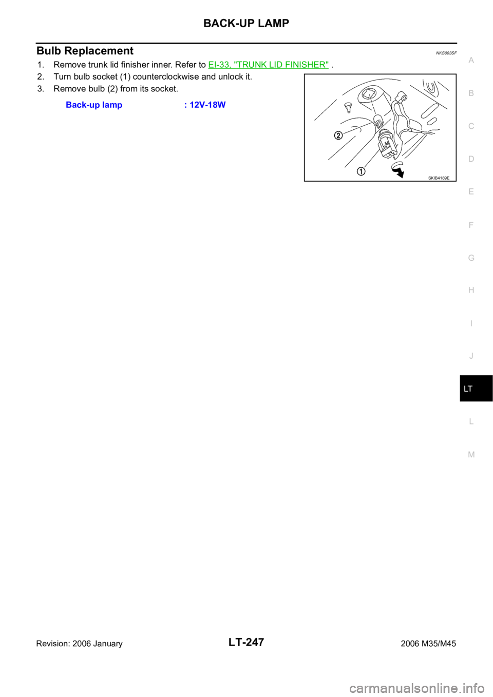
1. Remove trunk lid finisher inner. Refer to EI-33, "TRUNK LID FINISHER" .
2. Turn bulb socket (1) counterclockwise and unlock it.
3. Remove bulb (2) from its socket.
Back-up lamp : 12V-18W
SKIB4189E
Page 4675 of 5621
LT-248
BACK-UP LAMP
Revision: 2006 January2006 M35/M45
Removal and InstallationNKS003SG
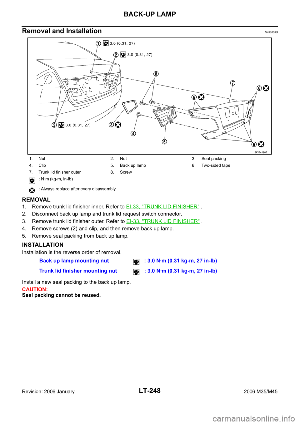
REMOVAL
1. Remove trunk lid finisher inner. Refer to EI-33, "TRUNK LID FINISHER" .
2. Disconnect back up lamp and trunk lid request switch connector.
3. Remove trunk lid finisher outer. Refer to EI-33, "
TRUNK LID FINISHER" .
4. Remove screws (2) and clip, and then remove back up lamp.
5. Remove seal packing from back up lamp.
INSTALLATION
Installation is the reverse order of removal.
Install a new seal packing to the back up lamp.
CAUTION:
Seal packing cannot be reused.
1. Nut 2. Nut 3. Seal packing
4. Clip 5. Back up lamp 6. Two-sided tape
7. Trunk lid finisher outer 8. Screw
: Nꞏm (kg-m, in-lb)
: Always replace after every disassembly.
SKIB4190E
Back up lamp mounting nut : 3.0 Nꞏm (0.31 kg-m, 27 in-lb)
Trunk lid finisher mounting nut : 3.0 Nꞏm (0.31 kg-m, 27 in-lb)
Page 4692 of 5621
PARKING, LICENSE PLATE AND TAIL LAMPS
LT-265
C
D
E
F
G
H
I
J
L
MA
B
LT
Revision: 2006 January2006 M35/M45
License Plate LampNKS003SV
BULB REPLACEMENT
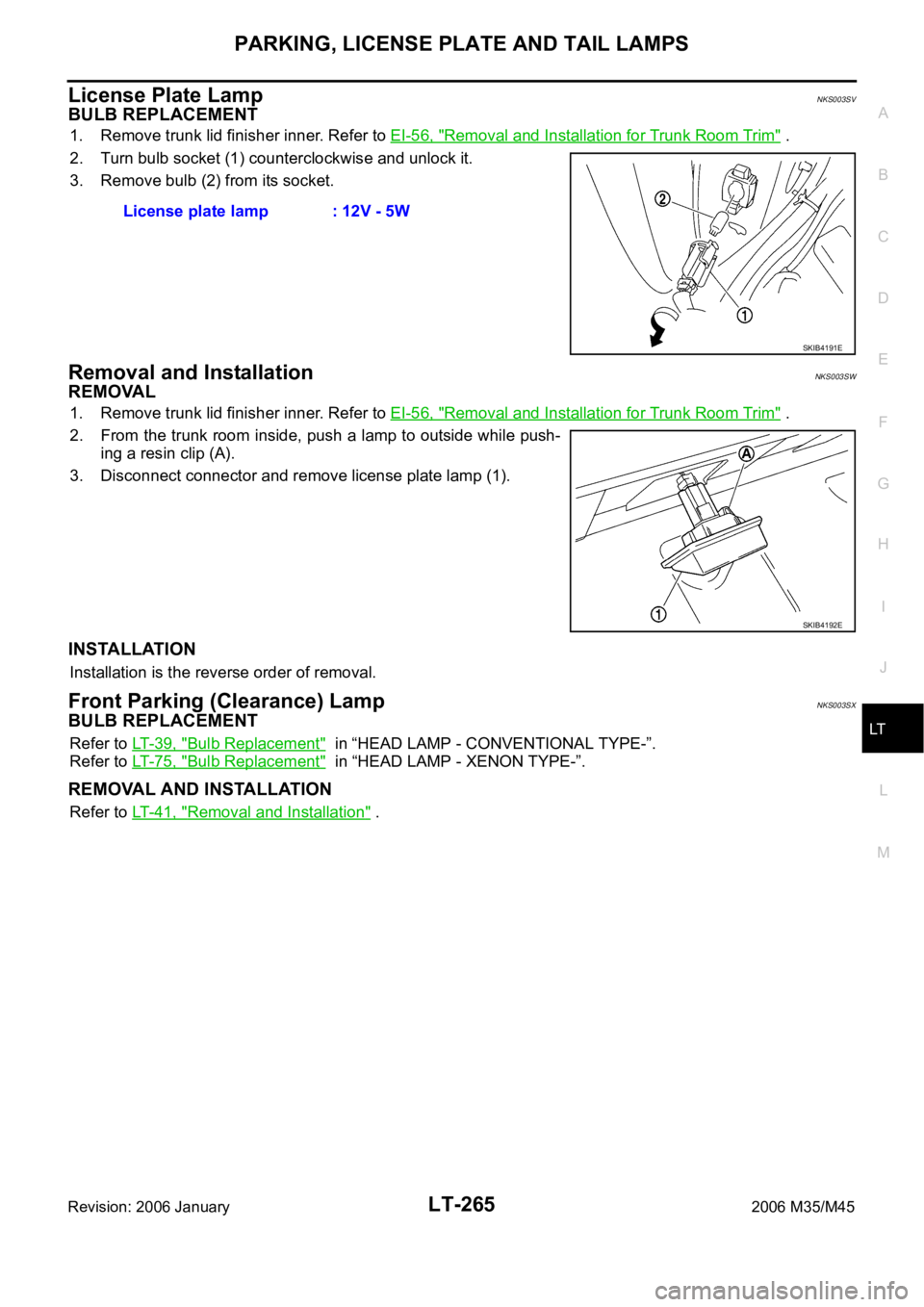
1. Remove trunk lid finisher inner. Refer to EI-56, "Removal and Installation for Trunk Room Trim" .
2. Turn bulb socket (1) counterclockwise and unlock it.
3. Remove bulb (2) from its socket.
Removal and InstallationNKS003SW
REMOVAL
1. Remove trunk lid finisher inner. Refer to EI-56, "Removal and Installation for Trunk Room Trim" .
2. From the trunk room inside, push a lamp to outside while push-
ing a resin clip (A).
3. Disconnect connector and remove license plate lamp (1).
INSTALLATION
Installation is the reverse order of removal.
Front Parking (Clearance) LampNKS003SX
BULB REPLACEMENT
Refer to LT- 3 9 , "Bulb Replacement" in “HEAD LAMP - CONVENTIONAL TYPE-”.
Refer to LT- 7 5 , "
Bulb Replacement" in “HEAD LAMP - XENON TYPE-”.
REMOVAL AND INSTALLATION
Refer to LT- 4 1 , "Removal and Installation" . License plate lamp : 12V - 5W
SKIB4191E
SKIB4192E
Page 4693 of 5621

LT-266
REAR COMBINATION LAMP
Revision: 2006 January2006 M35/M45
REAR COMBINATION LAMPPFP:26554
Bulb ReplacementNKS003SY
REAR TURN SIGNAL LAMP BULB, STOP/TAIL LAMP BULB
1. Remove trunk side finisher. Refer to EI-56, "Removal and Installation for Trunk Room Trim" .
2. Turn rear turn signal lamp bulb socket (1) counterclockwise and
unlock it.
3. Remove bulb (2).
Removal and InstallationNKS003SZ
REMOVAL
Rear Fender Side
1. Remove trunk side finisher. Refer to EI-56, "Removal and Installation for Trunk Room Trim" .
2. Disconnect rear combination lamp connector.
3. Remove rear combination lamp mounting nuts (A).
4. Pull the rear combination lamp (2) toward rear of the vehicle and
remove from the vehicle.
5. Remove seal packing (1) from the vehicle.
INSTALLATION
Installation is the reverse order of removal.
CAUTION:
Seal packing cannot be reused.Rear turn signal lamp : 12V - 21W (amber bulb)
Stop tail lamp : LED
SKIB4193E
: Nꞏm (kg-m, in-lb)
: Always replace after every disassembly
SKIB4194E
Page 4694 of 5621
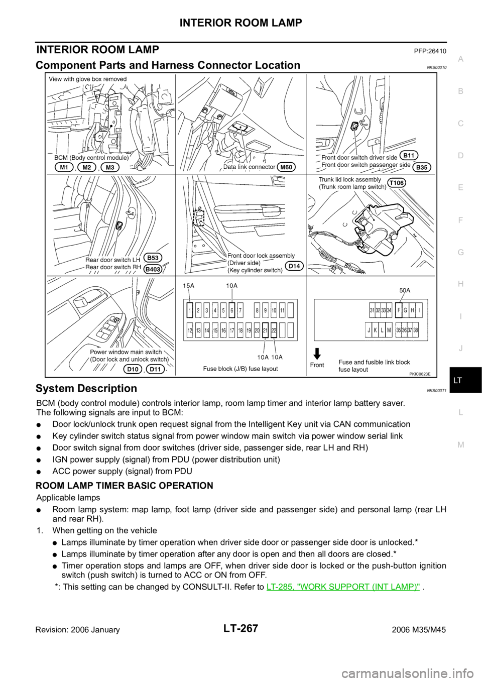
INTERIOR ROOM LAMP
LT-267
C
D
E
F
G
H
I
J
L
MA
B
LT
Revision: 2006 January2006 M35/M45
INTERIOR ROOM LAMPPFP:26410
Component Parts and Harness Connector LocationNKS003T0
System DescriptionNKS003T1
BCM (body control module) controls interior lamp, room lamp timer and interior lamp battery saver.
The following signals are input to BCM:
Door lock/unlock trunk open request signal from the Intelligent Key unit via CAN communication
Key cylinder switch status signal from power window main switch via power window serial link
Door switch signal from door switches (driver side, passenger side, rear LH and RH)
IGN power supply (signal) from PDU (power distribution unit)
ACC power supply (signal) from PDU
ROOM LAMP TIMER BASIC OPERATION
Applicable lamps
Room lamp system: map lamp, foot lamp (driver side and passenger side) and personal lamp (rear LH
and rear RH).
1. When getting on the vehicle
Lamps illuminate by timer operation when driver side door or passenger side door is unlocked.*
Lamps illuminate by timer operation after any door is open and then all doors are closed.*
Timer operation stops and lamps are OFF, when driver side door is locked or the push-button ignition
switch (push switch) is turned to ACC or ON from OFF.
*: This setting can be changed by CONSULT-II. Refer to LT- 2 8 5 , "
WORK SUPPORT (INT LAMP)" .
PKIC0623E
Page 4696 of 5621

INTERIOR ROOM LAMP
LT-269
C
D
E
F
G
H
I
J
L
MA
B
LT
Revision: 2006 January2006 M35/M45
through front door lock assembly (driver side) (key cylinder switch) terminals 5 and 4
through grounds M16 and M70.
When a signal, or combination of door open signals is received by BCM, ground is supplied
to foot lamp driver side and passenger side terminals 2
to personal lamp LH and RH terminals 1
to map lamp terminal 2 and 5
through BCM terminal 48,
to step lamp (driver side, passenger side, rear LH and RH) terminals 2
to kicking plate illumination (driver side and passenger side) terminals 2
through BCM terminal 47.
With power and ground supplied, the interior lamps illuminate.
SWITCH OPERATION
When any front door switch is ON (door is opened), ground is supplied
to step lamp (driver side, passenger side, rear LH and RH) terminals 2
to kicking plate illumination (driver side and passenger side) terminals 2
through BCM terminal 47.
And power is supplied
through BCM terminal 41
to step lamp (driver side, passenger side, rear LH and RH) terminals 1
to kicking plate illumination (driver side and passenger side) terminals 1.
When any door switch is ON (door is opened) and personal lamp and map lamp is DOOR position, ground is
supplied
to personal lamp LH and RH terminal 1
to map lamp terminals 2 and 5
through BCM terminal 48.
And power is supplied
through BCM terminal 41
to personal lamp LH and RH terminals 3
to map lamp terminal 3.
When map lamp switch is ON, ground is supplied
to map lamp terminal 1
through grounds M16 and M70.
And power is supplied
through BCM terminal 41
to map lamp terminal 3.
When personal lamp LH and RH switch is ON, ground is supplied
to personal lamp LH and RH terminals 2
through grounds M16 and M70.
And power is supplied
through BCM terminal 41
to personal lamp LH and RH terminals 3.
When trunk lid lock assembly (trunk room lamp switch) is ON, ground is supplied
to trunk room lamp (upper and lower) terminals 2
through trunk lid lock assembly (trunk room lamp switch) terminals 1 and 2
through grounds B5, B40 and B131.
And power is supplied
through BCM terminal 41
to trunk room lamp (upper and lower) terminals 1.
When vanity mirror lamp LH and RH switch is ON, ground is supplied