2006 INFINITI M35 trunk
[x] Cancel search: trunkPage 1182 of 5621
VEHICLE SECURITY (THEFT WARNING) SYSTEM
BL-243
C
D
E
F
G
H
J
K
L
MA
B
BL
Revision: 2006 January2006 M35/M45
TRUNK ROOM LAMP SWITCH CHECK
1. CHECK TRUNK ROOM LAMP SWITCH INPUT SIGNAL
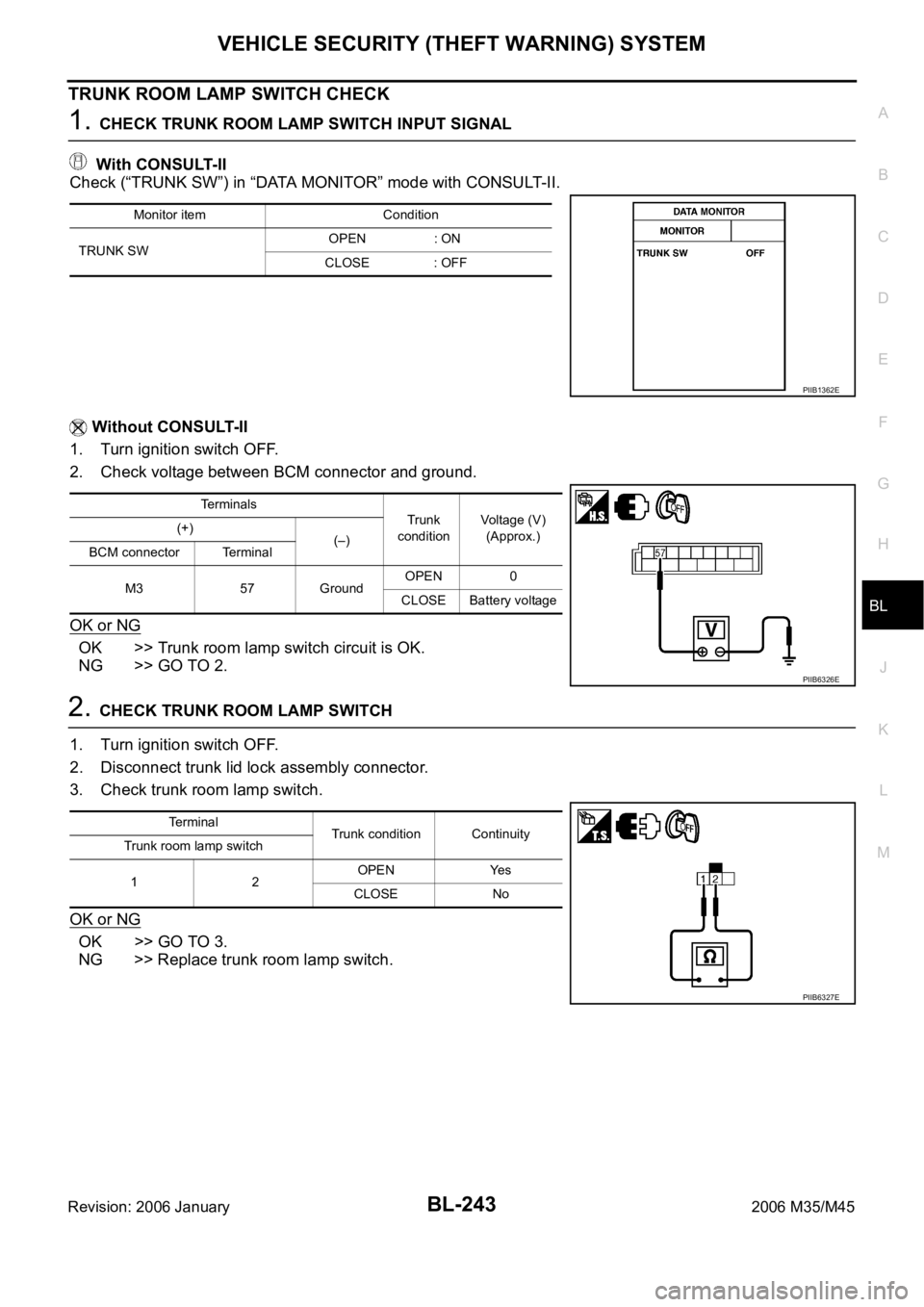
With CONSULT-II
Check (“TRUNK SW”) in “DATA MONITOR” mode with CONSULT-II.
Without CONSULT-II
1. Turn ignition switch OFF.
2. Check voltage between BCM connector and ground.
OK or NG
OK >> Trunk room lamp switch circuit is OK.
NG >> GO TO 2.
2. CHECK TRUNK ROOM LAMP SWITCH
1. Turn ignition switch OFF.
2. Disconnect trunk lid lock assembly connector.
3. Check trunk room lamp switch.
OK or NG
OK >> GO TO 3.
NG >> Replace trunk room lamp switch.
Monitor item Condition
TRUNK SWOPEN : ON
CLOSE : OFF
PIIB1362E
Terminals
Trunk
conditionVoltage (V)
(Approx.) (+)
(–)
BCM connector Terminal
M3 57 GroundOPEN 0
CLOSE Battery voltage
PIIB6326E
Terminal
Trunk condition Continuity
Trunk room lamp switch
12OPEN Yes
CLOSE No
PIIB6327E
Page 1183 of 5621
BL-244
VEHICLE SECURITY (THEFT WARNING) SYSTEM
Revision: 2006 January2006 M35/M45
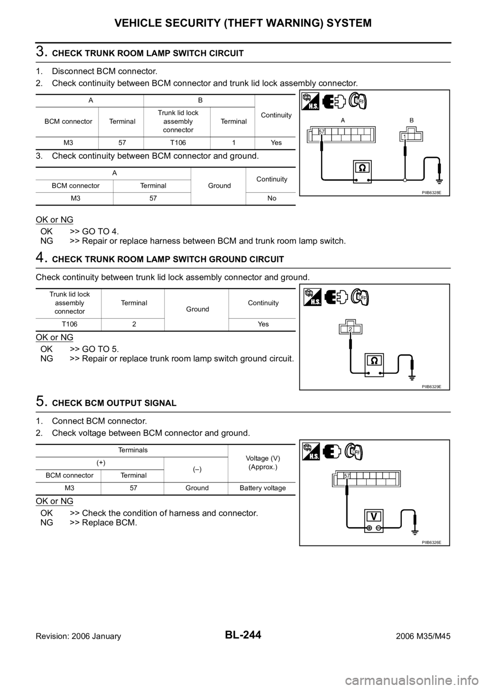
3. CHECK TRUNK ROOM LAMP SWITCH CIRCUIT
1. Disconnect BCM connector.
2. Check continuity between BCM connector and trunk lid lock assembly connector.
3. Check continuity between BCM connector and ground.
OK or NG
OK >> GO TO 4.
NG >> Repair or replace harness between BCM and trunk room lamp switch.
4. CHECK TRUNK ROOM LAMP SWITCH GROUND CIRCUIT
Check continuity between trunk lid lock assembly connector and ground.
OK or NG
OK >> GO TO 5.
NG >> Repair or replace trunk room lamp switch ground circuit.
5. CHECK BCM OUTPUT SIGNAL
1. Connect BCM connector.
2. Check voltage between BCM connector and ground.
OK or NG
OK >> Check the condition of harness and connector.
NG >> Replace BCM.
AB
Continuity
BCM connector TerminalTrunk lid lock
assembly
connectorTerminal
M3 57 T106 1 Yes
A
GroundContinuity
BCM connector Terminal
M3 57 No
PIIB6328E
Trunk lid lock
assembly
connectorTerminal
GroundContinuity
T106 2 Yes
PIIB6329E
Terminals
Voltage (V)
(Approx.) (+)
(–)
BCM connector Terminal
M3 57 Ground Battery voltage
PIIB6326E
Page 1223 of 5621
BL-284
BODY REPAIR
Revision: 2006 January2006 M35/M45
BODY REPAIRPFP:60100
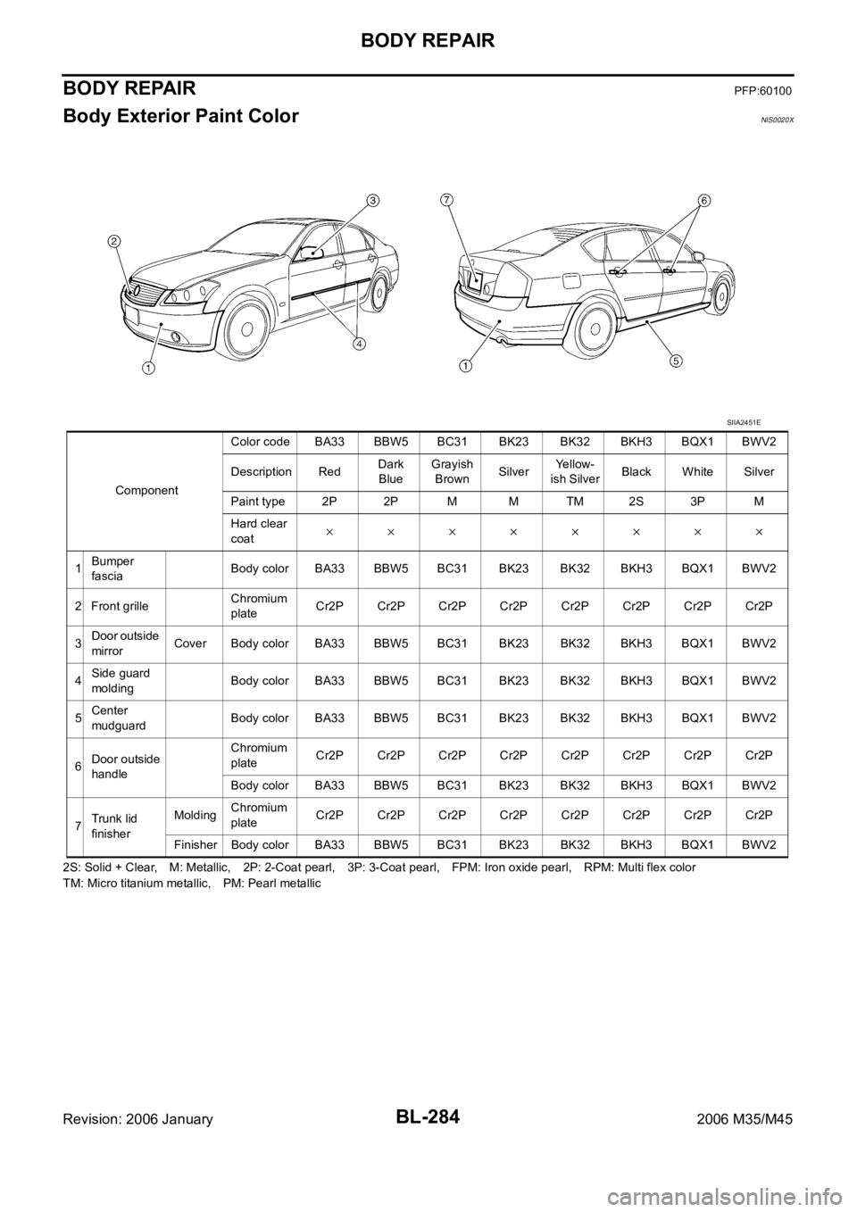
Body Exterior Paint ColorNIS0020X
2S: Solid + Clear, M: Metallic, 2P: 2-Coat pearl, 3P: 3-Coat pearl, FPM: Iron oxide pearl, RPM: Multi flex color
TM: Micro titanium metallic, PM: Pearl metallic ComponentColor code BA33 BBW5 BC31 BK23 BK32 BKH3 BQX1 BWV2
Description RedDark
BlueGrayish
BrownSilverYellow-
ish SilverBlack White Silver
Paint type 2P 2P M M TM 2S 3P M
Hard clear
coat
1Bumper
fasciaBody color BA33 BBW5 BC31 BK23 BK32 BKH3 BQX1 BWV2
2 Front grilleChromium
plateCr2P Cr2P Cr2P Cr2P Cr2P Cr2P Cr2P Cr2P
3Door outside
mirrorCover Body color BA33 BBW5 BC31 BK23 BK32 BKH3 BQX1 BWV2
4Side guard
moldingBody color BA33 BBW5 BC31 BK23 BK32 BKH3 BQX1 BWV2
5Center
mudguardBody color BA33 BBW5 BC31 BK23 BK32 BKH3 BQX1 BWV2
6Door outside
handleChromium
plateCr2P Cr2P Cr2P Cr2P Cr2P Cr2P Cr2P Cr2P
Body color BA33 BBW5 BC31 BK23 BK32 BKH3 BQX1 BWV2
7Trunk lid
finisherMoldingChromium
plateCr2P Cr2P Cr2P Cr2P Cr2P Cr2P Cr2P Cr2P
Finisher Body color BA33 BBW5 BC31 BK23 BK32 BKH3 BQX1 BWV2
SIIA2451E
Page 1227 of 5621

BL-288
BODY REPAIR
Revision: 2006 January2006 M35/M45
1. Hood
2. Front fender (RH&LH)
3. Side body assembly (RH&LH)
4. Outer front pillar reinforcement (RH&LH)
5. Center pillar reinforcement (RH&LH)
6. Outer roof side rail reinforcement (RH&LH)
7. Outer sill reinforcement (RH&LH)
8. Inner roof side rail (RH&LH)
9. Inner center pillar (RH&LH)
10. Front roof rail brace (RH&LH)
11. Outer sill (RH&LH)
12. Inner rear pillar assembly (RH&LH)
13. Inner rear pillar rear (RH&LH)
14. Inner rear pillar reinforcement (RH&LH)
15. Outer rear wheelhouse (RH&LH)
16. Outer rear wheelhouse extension (RH&LH)
17. Inner rear wheelhouse (RH&LH)
18. Side parcel shelf assembly (RH&LH)
19. Seat back support (RH&LH)
20. Parcel shelf assembly
21. Rear waist
22. Roof assembly
23. Front roof rail
24. Front roof bow
25. Rear roof bow
26. Rear roof rail
27. Rear fender assembly (RH&LH)
28. Rear fender extension (RH&LH)
29. Rear bumper side bracket
30. Fuel filler lid (RH)
31. Rear panel assembly
32. Upper rear bumper retainer
33. Lower rear bumper retainer
34. Front door assembly (RH&LH)
35. Outer front door panel (RH&LH)
36. Rear door assembly (RH&LH)
37. Outer rear door panel (RH&LH)
38. Trunk lid
39. Front bumper reinforcement
40. Rear bumper stay
41. Rear bumper reinforcement
Page 3006 of 5621
EI-1
EXTERIOR & INTERIOR
I BODY
CONTENTS
C
D
E
F
G
H
J
K
L
M
SECTION EI
A
B
EI
Revision: 2006 January2006 M35/M45
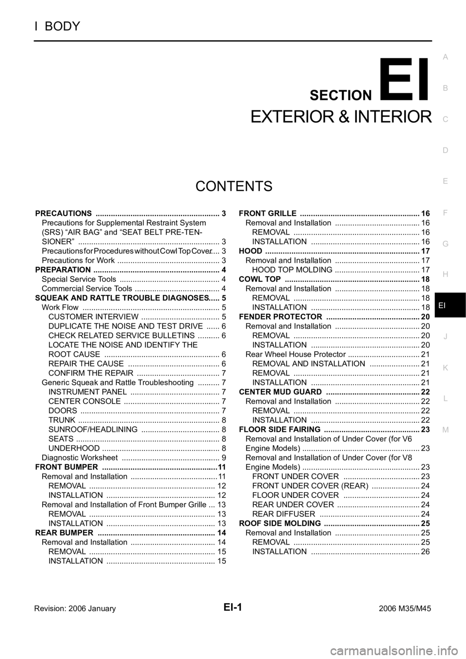
EXTERIOR & INTERIOR
PRECAUTIONS .......................................................... 3
Precautions for Supplemental Restraint System
(SRS) “AIR BAG” and “SEAT BELT PRE-TEN-
SIONER” .................................................................. 3
Precautions for Procedures without Cowl Top Cover ..... 3
Precautions for Work ...........................................
..... 3
PREPARATION ........................................................... 4
Special Service Tools ............................................... 4
Commercial Service Tools ........................................ 4
SQUEAK AND RATTLE TROUBLE DIAGNOSES ..... 5
Work Flow ................................................................ 5
CUSTOMER INTERVIEW ..................................... 5
DUPLICATE THE NOISE AND TEST DRIVE ....... 6
CHECK RELATED SERVICE BULLETINS ........... 6
LOCATE THE NOISE AND IDENTIFY THE
ROOT CAUSE ...................................................... 6
REPAIR THE CAUSE ........................................... 6
CONFIRM THE REPAIR ....................................... 7
Generic Squeak and Rattle Troubleshooting ........... 7
INSTRUMENT PANEL .......................................... 7
CENTER CONSOLE ............................................. 7
DOORS ................................................................. 7
TRUNK .................................................................. 8
SUNROOF/HEADLINING ..................................... 8
SEATS ................................................................... 8
UNDERHOOD ....................................................... 8
Diagnostic Worksheet .............................................. 9
FRONT BUMPER ......................................................11
Removal and Installation ......................................... 11
REMOVAL ........................................................
... 12
INSTALLATION ................................................... 12
Removal and Installation of Front Bumper Grille ... 13
REMOVAL ........................................................
... 13
INSTALLATION ................................................... 13
REAR BUMPER ....................................................
... 14
Removal and Installation ........................................ 14
REMOVAL ........................................................
... 15
INSTALLATION ................................................... 15FRONT GRILLE ........................................................ 16
Removal and Installation ........................................ 16
REMOVAL ........................................................
... 16
INSTALLATION ................................................... 16
HOOD ........................................................................ 17
Removal and Installation ........................................ 17
HOOD TOP MOLDING ........................................ 17
COWL TOP ............................................................... 18
Removal and Installation ........................................ 18
REMOVAL ........................................................
... 18
INSTALLATION ................................................
... 18
FENDER PROTECTOR ............................................ 20
Removal and Installation ........................................ 20
REMOVAL ........................................................
... 20
INSTALLATION ................................................... 20
Rear Wheel House Protector .................................. 21
REMOVAL AND INSTALLATION ........................ 21
REMOVAL ........................................................
... 21
INSTALLATION ................................................... 21
CENTER MUD GUARD ............................................ 22
Removal and Installation ........................................ 22
REMOVAL ........................................................
... 22
INSTALLATION ................................................... 22
FLOOR SIDE FAIRING ............................................. 23
Removal and Installation of Under Cover (for V6
Engine Models) ....................................................... 23
Removal and Installation of Under Cover (for V8
Engine Models) ....................................................... 23
FRONT UNDER COVER .................................... 23
FRONT UNDER COVER (REAR) ....................... 24
FLOOR UNDER COVER .................................... 24
REAR UNDER COVER ....................................... 24
REAR DIFFUSER ............................................... 24
ROOF SIDE MOLDING ............................................. 25
Removal and Installation ........................................ 25
REMOVAL ........................................................
... 25
INSTALLATION ................................................... 26
Page 3007 of 5621
EI-2Revision: 2006 January2006 M35/M45 DOOR SASH MOLDING ........................................... 27
Removal and Installation ........................................ 27
FRONT DOOR SASH MOLDING ........................ 27
REAR DOOR SUSH MOLDING .......................... 27
DOOR SASH OUTER COVER ............................ 28
REAR DOOR CORNER COVER ........................ 28
DOOR OUTSIDE MOLDING ..................................... 29
Removal and Installation ........................................ 29
FRONT DOOR OUTSIDE MOLDING .................. 29
REAR DOOR OUTSIDE MOLDING .................... 30
SIDE GUARD MOLDING .......................................... 31
Removal and Installation ........................................ 31
REMOVAL ........................................................
... 31
INSTALLATION .................................................... 31
DOOR PARTING SEAL ............................................ 32
Removal and Installation ........................................ 32
FRONT DOOR PARTING SEAL .......................... 32
REAR DOOR PARTING SEAL ............................ 32
TRUNK LID FINISHER .............................................. 33
Removal and Installation ........................................ 33
REMOVAL ........................................................
... 33
INSTALLATION .................................................... 33
DOOR FINISHER ...................................................... 34
Removal and Installation ........................................ 34
FRONT AND REAR DOOR FINISHER ............... 34
FRONT DOOR SASH COVER INNER ................ 36
REAR DOOR SASH COVER INNER .................. 36BODY SIDE TRIM ..................................................... 37
Removal and Installation ......................................... 37
FRONT PILLAR GARNISH .................................. 38
FRONT KICKING PLATE OUTER ....................... 38
FRONT KICKING PLATE INNER ........................ 38
FRONT BODY SIDE WELT ................................. 39
CENTER PILLAR LOWER GARNISH ................. 39
CENTER PILLAR UPPER GARNISH .................. 39
REAR KICKING PLATE OUTER ......................... 40
REAR KICKING PLATE INNER ........................... 40
REAR BODY SIDE WELT .................................... 40
REAR WHEEL HOUSE GARNISH ...................... 41
REAR PILLAR FINISHER .................................... 41
REAR PARCEL SHELF FINISHER ........................... 42
Removal and Installation ......................................... 42
REMOVAL ............................................................ 42
INSTALLATION .................................................... 43
Rear Window Sunshade ......................................... 43
REMOVAL AND INSTALLATION ......................... 43
SUNSHADE ............................................................... 44
Component Parts and Harness Connector Location ... 44
Schematic ............................................................... 45
Wiring Diagram—SHADE— .................................... 46
Terminals and Reference Values for Rear Sun-
shade Unit ............................................................... 49
FLOOR TRIM ............................................................. 50
Removal and Installation ......................................... 50
REMOVAL ............................................................ 50
INSTALLATION .................................................... 51
HEADLINING ............................................................. 52
Removal and Installation ......................................... 52
REMOVAL ............................................................ 53
INSTALLATION .................................................... 55
TRUNK ROOM TRIM & TRUNK LID FINISHER ....... 56
Removal and Installation for Trunk Room Trim ....... 56
REMOVAL ............................................................ 57
INSTALLATION .................................................... 57
REMOVAL AND INSTALLATION OF TRUNK LID
FINISHER INNER ................................................ 57
Page 3013 of 5621
EI-8
SQUEAK AND RATTLE TROUBLE DIAGNOSES
Revision: 2006 January2006 M35/M45
TRUNK
Trunk noises are often caused by a loose jack or loose items put into the trunk by the owner.
In addition look for:
1. Trunk lid dumpers out of adjustment
2. Trunk lid striker out of adjustment
3. The trunk lid torsion bars knocking together
4. A loose license plate or bracket
Most of these incidents can be repaired by adjusting, securing or insulating the item(s) or component(s) caus-
ing the noise.
SUNROOF/HEADLINING
Noises in the sunroof/headlining area can often be traced to one of the following:
1. Sunroof lid, rail, linkage or seals making a rattle or light knocking noise
2. Sunvisor shaft shaking in the holder
3. Front or rear windshield touching headlining and squeaking
Again, pressing on the components to stop the noise while duplicating the conditions can isolate most of these
incidents. Repairs usually consist of insulating with felt cloth tape.
SEATS
When isolating seat noise it's important to note the position the seat is in and the load placed on the seat when
the noise is present. These conditions should be duplicated when verifying and isolating the cause of the
noise.
Cause of seat noise include:
1. Headrest rods and holder
2. A squeak between the seat pad cushion and frame
3. The rear seatback lock and bracket
These noises can be isolated by moving or pressing on the suspected components while duplicating the con-
ditions under which the noise occurs. Most of these incidents can be repaired by repositioning the component
or applying urethane tape to the contact area.
UNDERHOOD
Some interior noise may be caused by components under the hood or on the engine wall. The noise is then
transmitted into the passenger compartment.
Causes of transmitted underhood noise include:
1. Any component mounted to the engine wall
2. Components that pass through the engine wall
3. Engine wall mounts and connectors
4. Loose radiator mounting pins
5. Hood bumpers out of adjustment
6. Hood striker out of adjustment
These noises can be difficult to isolate since they cannot be reached from the interior of the vehicle. The best
method is to secure, move or insulate one component at a time and test drive the vehicle. Also, engine RPM
or load can be changed to isolate the noise. Repairs can usually be made by moving, adjusting, securing, or
insulating the component causing the noise.
Page 3020 of 5621
REAR BUMPER
EI-15
C
D
E
F
G
H
J
K
L
MA
B
EI
Revision: 2006 January2006 M35/M45
REMOVAL
1. Fully open trunk lid assembly.
2. Remove trunk floor carpet, trunk side box assembly, trunk rear plate, and trunk side finisher. Refer to EI-
56, "TRUNK ROOM TRIM & TRUNK LID FINISHER" .
3. Remove rear combination lamp (LH/RH). Refer to LT-266, "
Removal and Installation" .
4. Remove clips of rear combination lamp lower. (Figure to illustration B)
5. Remove clips of bumper fascia lower side.
6. Remove screws of bumper fascia left/right side. (Figure to illustration C)
7. Remove bumper fascia left/right bolt from trunk room inside. (Figure to illustration A)
8. Remove clip and bumper clamp from bumper fascia upper side, and then pull out bumper fascia toward
rear of vehicle. (Figure to illustration D)
9. Remove bumper fascia assembly.
CAUTION:
When removing bumper fascia, 2 workers are required so as to prevent it from dropping.
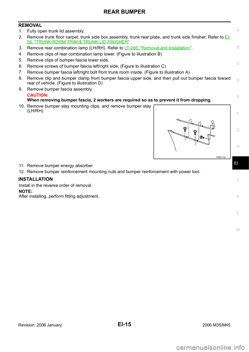
10. Remove bumper stay mounting clips, and remove bumper stay
(LH/RH).
11. Remove bumper energy absorber.
12. Remove bumper reinforcement mounting nuts and bumper reinforcement with power tool.
INSTALLATION
Install in the reverse order of removal.
NOTE:
After installing, perform fitting adjustment.
PIIB4119J