2006 INFINITI M35 trunk
[x] Cancel search: trunkPage 1092 of 5621
![INFINITI M35 2006 Factory Service Manual INTELLIGENT KEY SYSTEM/ENGINE START FUNCTION
BL-153
C
D
E
F
G
H
J
K
L
MA
B
BL
Revision: 2006 January2006 M35/M45
CAUTION:
When CAN COMM 1 [U1000] and CAN COMM 2 [U1010] are displayed, give priority to INFINITI M35 2006 Factory Service Manual INTELLIGENT KEY SYSTEM/ENGINE START FUNCTION
BL-153
C
D
E
F
G
H
J
K
L
MA
B
BL
Revision: 2006 January2006 M35/M45
CAUTION:
When CAN COMM 1 [U1000] and CAN COMM 2 [U1010] are displayed, give priority to](/manual-img/42/57023/w960_57023-1091.png)
INTELLIGENT KEY SYSTEM/ENGINE START FUNCTION
BL-153
C
D
E
F
G
H
J
K
L
MA
B
BL
Revision: 2006 January2006 M35/M45
CAUTION:
When CAN COMM 1 [U1000] and CAN COMM 2 [U1010] are displayed, give priority to performing trouble diagnosis.
DATA MONITOR
ENG START SW
[B2556]Condition that push-button ignition switch is pushed is
detected continuously for 100 seconds or moreCheck push-button igni-
tion switchBL-168
VEHICLE SPEED
[B2557]Some differences occur on one or more vehicle speed
inputs of Intelligent Key unitCheck vehicle speed sig-
nalBL-169
SHIFT POSITION
[B2558]
There is a difference between the shift position input
via CAN communication and the P position input by
detent switch
Vehicle speed (5 km/h or more) is detected continu-
ously for 10 seconds or more even if the shift posi-
tion is detected in P position when the power supply
position is in ON positionCheck shift position inputBL-172
PDU
[B2559]Internal malfunction is detected in PDU Replace PDUBL-174
START POW SUP CIRC
[B2560]Though the engine start operation is not performed,
starter relay in IPDM E/R is ONCheck starter power sup-
plyBL-174
LOW VOLTAGE
[B2562]Battery power supply input to Intelligent Key unit (8.8V
or less) is detected continuously for 1.5 seconds or
moreCheck battery low volt-
ageBL-177
HI VOLTAGE
[B2563]Battery power supply input to Intelligent Key unit (18V
or more) is detected continuously for 90 seconds or
moreCheck for battery high
voltageBL-178
NATS MALFUNCTION
[B2590]Malfunction is detected in immobilizer systemCheck (IVIS) NATS trou-
ble diagnosis procedureBL-268
Suspect Systems
[DTC]Diagnostic item is detected when... Repair work Reference page
Monitor item Content
DR REQ SW Indicates [ON/OFF] condition of door request switch (driver side).
AS REQ SW Indicates [ON/OFF] condition of door request switch (passenger side).
BD/TR REQ SW Indicates [ON/OFF] condition of trunk opener request switch.
ON POS Indicates [ON/OFF] condition of ignition switch in ON position.
ACC POS Indicates [ON/OFF] condition of ignition switch in ACC position.
DOOR STAT SW Indicates [ON/OFF] condition of door unlock sensor.
STOP LAMP SW Indicates [ON/OFF] condition of stop lamp switch.
P RANGE SW Indicates [ON/OFF] condition of park position switch.
TR CANCEL SW* Indicates [ON/OFF] condition of trunk cancel switch.
DOOR LOCK SIG* Indicates [ON/OFF] condition of door lock signal from Intelligent Key remote controller button.
DOOR UNLOCK SIG* Indicates [ON/OFF] condition of door unlock signal from Intelligent Key remote controller button.
KEYLESS TRUNK* Indicates [ON/OFF] condition of trunk open signal from Intelligent Key remote controller button.
KEYLESS PANIC* Indicates [ON/OFF] condition of panic alarm signal from Intelligent Key remote controller button.
DOOR SW DR*Indicates [OPEN/CLOSE] condition of front door switch driver side from BCM via CAN communica-
tion line.
DOOR SW AS*Indicates [OPEN/CLOSE] condition of front door switch passenger side from BCM via CAN commu-
nication line.
DOOR SW RR* Indicates [OPEN/CLOSE] condition of rear door switch LH from BCM via CAN communication line.
DOOR SW RL* Indicates [OPEN/CLOSE] condition of rear door switch RH from BCM via CAN communication line.
DOOR BK SW* Indicates [OPEN/CLOSE] condition of back door switch from BCM via CAN communication line.
Page 1093 of 5621
![INFINITI M35 2006 Factory Service Manual BL-154
INTELLIGENT KEY SYSTEM/ENGINE START FUNCTION
Revision: 2006 January2006 M35/M45
*: Select “SELECTION FROM MENU”.
WORK SUPPORT
TRUNK SW*Indicates [OPEN/CLOSE] condition of trunk room lamp sw INFINITI M35 2006 Factory Service Manual BL-154
INTELLIGENT KEY SYSTEM/ENGINE START FUNCTION
Revision: 2006 January2006 M35/M45
*: Select “SELECTION FROM MENU”.
WORK SUPPORT
TRUNK SW*Indicates [OPEN/CLOSE] condition of trunk room lamp sw](/manual-img/42/57023/w960_57023-1092.png)
BL-154
INTELLIGENT KEY SYSTEM/ENGINE START FUNCTION
Revision: 2006 January2006 M35/M45
*: Select “SELECTION FROM MENU”.
WORK SUPPORT
TRUNK SW*Indicates [OPEN/CLOSE] condition of trunk room lamp switch from BCM via CAN communication
line.
VEHICLE SPEED* Indicates [km/h] condition of vehicle speed.Monitor item Content
Monitor item Description
CONFIRM KEY FOB ID It can be checked whether Intelligent Key ID code is registered or not in this mode.
TAKE OUT FROM WINDOW
WARNTake away warning chime (from window) mode can be changed to operate (ON) or not operate
(OFF) with this mode. The operation mode will be changed when “CHANGE SETT” on CON-
SULT-II screen is touched.
LOW BAT OF KEY FOB WARNIntelligent Key low battery warning mode can be changed to operate (ON) or not operate (OFF)
with this mode. The operation mode will be changed when “CHANGE SETT” on CONSULT-II
screen is touched.
ANSWER BACK FUNCTIONHazard and buzzer reminder function mode can be changed to operate (ON) or not operate
(OFF) with this mode. The operation mode will be changed when “CHANGE SETT” on CON-
SULT-II screen is touched.
SELECTIVE UNLOCK FUNC-
TIONSelective unlock function mode can be changed to operate (ON) or not operate (OFF) with this
mode. The operation mode will be changed when “CHANGE SETT” on CONSULT-II screen is
touched.
ANTI KEY LOCK IN FUNCTIONKey reminder function mode can be changed to operate (ON) or not operate (OFF) with this
mode. The operation mode will be changed when “CHANGE SETT” on CONSULT-II screen is
touched.
HORN WITH KEYLESS LOCKHorn reminder function mode by Intelligent Key button can be changed to operate (ON) or not
operate (OFF) with this mode. The operation mode will be changed when “CHANGE SETT” on
CONSULT-II screen is touched.
HAZARD ANSWER BACKHazard reminder function mode can be selected from the following with this mode. The operation
mode will be changed when “CHANGE SETT” on CONSULT-II screen is touched.
LOCK ONLY: Door lock operation only
UNLOCK ONLY: Door unlock operation only
LOCK/UNLOCK: Lock/Unlock operation
OFF: Non-operation
ANSWER BACK WITH I-KEY
LOCKBuzzer reminder function (lock operation) mode by door request switch (driver side and passen-
ger side) can be selected from the following with this mode. The operation mode will be changed
when “CHANGE SETT” on CONSULT-II screen is touched.
HORN CHIRP: Sound horn
BUZZER: Sound Intelligent Key warning buzzer
OFF: Non-operation
ANSWER BACK WITH I-KEY
UNLOCKBuzzer reminder function (unlock operation) mode by door request switch can be changed to
operate (ON) or not operate (OFF) with this mode.
AUTO RELOCK TIMERAuto door lock timer mode can select the following with this mode.
1 min
5 min
OFF: Non-operation
PANIC ALARM DELAYPanic alarm button's pressing time on Intelligent Key remote control button can be selected from
the following with this mode. The operation mode will be changed when “CHANGE SETT” on
CONSULT-II screen is touched.
0.5 sec
1.5 sec
OFF: Non-operation
TRUNK/GLASS HATCH OPENBuzzer reminder function mode by trunk opener request switch can be changed to operate (ON)
or not operate (OFF) with this mode. The operation mode will be changed when “CHANGE
SETT” on CONSULT-II screen is touched.
Page 1094 of 5621

INTELLIGENT KEY SYSTEM/ENGINE START FUNCTION
BL-155
C
D
E
F
G
H
J
K
L
MA
B
BL
Revision: 2006 January2006 M35/M45
ACTIVE TEST
TRUNK OPEN DELAYTrunk button's pressing time on Intelligent Key button can be selected from the following with this
mode. The operation mode will be changed when “CHANGE SETT” on CONSULT-II screen is
touched.0.5 sec
1.5 sec
OFF: Non-operation
P/W DOWN DELAYUnlock button's pressing time on Intelligent Key button can be selected from the following with
this mode. The operation mode will be changed when “CHANGE SETT” on CONSULT-II screen
is touched.
3 sec
5 sec
OFF: Non-operation
ENGINE START BY I-KEYEngine start function mode can be changed to operate (ON) or not operate (OFF) with this mode.
The operation mode will be changed when “CHANGE SETT” on CONSULT-II screen is touched.
LOCK/UNLOCK BY I-KEYDoor lock/unlock function by door request switch (driver side, passenger side and trunk) mode
can be changed to operate (ON) or not operate (OFF) with this mode. The operation mode will be
changed when “CHANGE SETT” on CONSULT-II screen is touched. Monitor item Description
Test item Description
DOOR LOCK/UNLOCKThis test is able to check door lock/unlock operation.
The all door lock actuators are locked when “LOCK” on CONSULT-II screen is touched.
The all door lock actuators are unlocked when “ALL UNLK” on CONSULT-II screen is touched.
The door lock actuator (driver side) is unlocked when “DR UNLK” on CONSULT-II screen is
touched.
The door lock actuator (passenger side) is unlocked when “AS UNLK” on CONSULT- II screen
is touched.
The trunk lid opener actuator is open when “TRUNK OPEN” on CONSULT- II screen is
touched.
ANTENNAThis test is able to check Intelligent Key antenna operation.
When the following conditions are met, hazard warning lamps flash.
Inside key antenna (Instrument center) detects Intelligent Key, when “ROOM ANT1” on CON-
SULT-II screen is touched.
Inside key antenna (Center console) detects Intelligent Key, when “ROOM ANT2” on CON-
SULT-II screen is touched.
Inside key antenna (rear seat) detects Intelligent Key, when “ROOM ANT3” on CONSULT-II
screen is touched.
Inside key antenna (Trunk room) detects Intelligent Key, when “LAG ANT1” on CONSULT-II
screen is touched.
Outside key antenna (Driver side) detects Intelligent Key, when “DRIVER ANT” on CONSULT-II
screen is touched.
Outside key antenna (Passenger side) detects Intelligent Key, when “ASSIST ANT” on CON-
SULT-II screen is touched.
Outside key antenna (Trunk room) detects Intelligent Key, when “BD/TR ANT” on CONSULT-II
screen is touched.
OUTSIDE BUZZERThis test is able to check Intelligent Key warning buzzer operation.
Intelligent Key warning buzzer sounds when “ON” on CONSULT-II screen is touched.
INSIDE BUZZERThis test is able to check warning chime into combination meter operation.
Take away warning chime sounds when “TAKE OUT” on CONSULT-II screen is touched.
Key warning chime sounds when “KEY WARN” on CONSULT-II screen is touched.
P position warning chime sounds when “P RNG WARN” on CONSULT-II screen is touched.
ACC warning chime sounds when “ACC WARN” on CONSULT-II screen is touched.
Page 1122 of 5621
INTELLIGENT KEY SYSTEM/ENGINE START FUNCTION
BL-183
C
D
E
F
G
H
J
K
L
MA
B
BL
Revision: 2006 January2006 M35/M45
Check Inside Key AntennaNIS001Z5
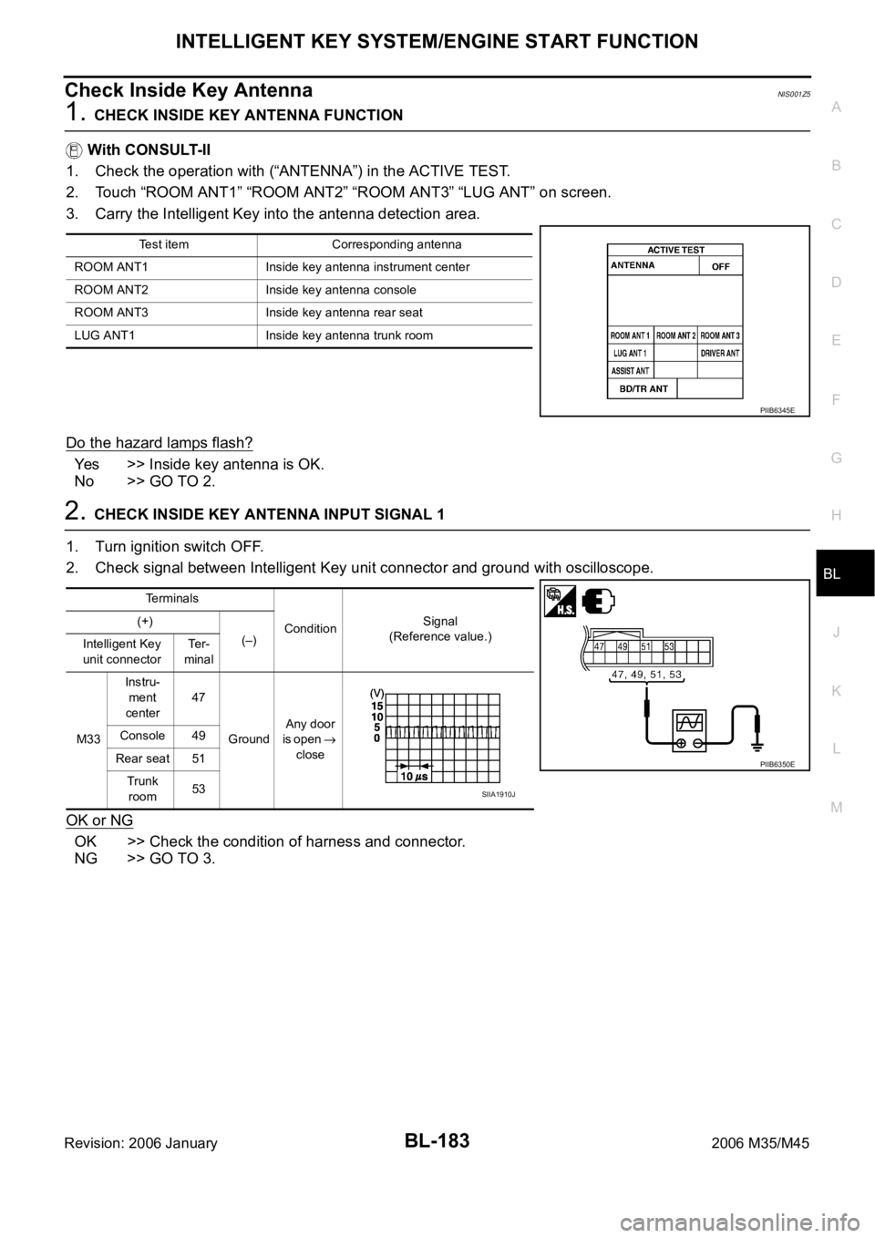
1. CHECK INSIDE KEY ANTENNA FUNCTION
With CONSULT-II
1. Check the operation with (“ANTENNA”) in the ACTIVE TEST.
2. Touch “ROOM ANT1” “ROOM ANT2” “ROOM ANT3” “LUG ANT” on screen.
3. Carry the Intelligent Key into the antenna detection area.
Do the hazard lamps flash?
Yes >> Inside key antenna is OK.
No >> GO TO 2.
2. CHECK INSIDE KEY ANTENNA INPUT SIGNAL 1
1. Turn ignition switch OFF.
2. Check signal between Intelligent Key unit connector and ground with oscilloscope.
OK or NG
OK >> Check the condition of harness and connector.
NG >> GO TO 3.
Test item Corresponding antenna
ROOM ANT1 Inside key antenna instrument center
ROOM ANT2 Inside key antenna console
ROOM ANT3 Inside key antenna rear seat
LUG ANT1 Inside key antenna trunk room
PIIB6345E
Terminals
ConditionSignal
(Reference value.) (+)
(–)
Intelligent Key
unit connectorTe r -
minal
M33Instru-
ment
center47
GroundAny door
is open
close Console 49
Rear seat 51
Trunk
room53
PIIB6350E
SIIA1910J
Page 1123 of 5621
BL-184
INTELLIGENT KEY SYSTEM/ENGINE START FUNCTION
Revision: 2006 January2006 M35/M45
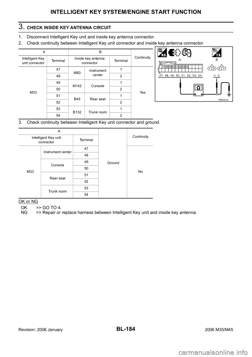
3. CHECK INSIDE KEY ANTENNA CIRCUIT
1. Disconnect Intelligent Key unit and inside key antenna connector.
2. Check continuity between Intelligent Key unit connector and inside key antenna connector.
3. Check continuity between Intelligent Key unit connector and ground.
OK or NG
OK >> GO TO 4.
NG >> Repair or replace harness between Intelligent Key unit and inside key antenna.
AB
Continuity
Intelligent Key
unit connectorTerminalInside key antenna
connectorTerminal
M3347
M83Instrument
center1
Ye s 48 2
49
M142 Console1
50 2
51
B45 Rear seat1
52 2
53
B132 Trunk room1
54 2
A
GroundContinuity
Intelligent Key unit
connectorTe r m i n a l
M33Instrument center47
No 48
Console49
50
Rear seat51
52
Trunk room53
54
PIIB6351E
Page 1124 of 5621
INTELLIGENT KEY SYSTEM/ENGINE START FUNCTION
BL-185
C
D
E
F
G
H
J
K
L
MA
B
BL
Revision: 2006 January2006 M35/M45
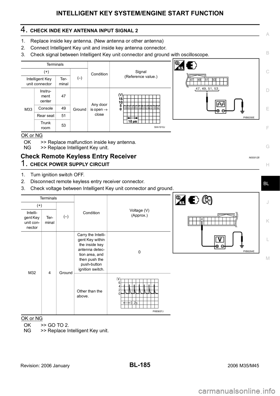
4. CHECK INDE KEY ANTENNA INPUT SIGNAL 2
1. Replace inside key antenna. (New antenna or other antenna)
2. Connect Intelligent Key unit and inside key antenna connector.
3. Check signal between Intelligent Key unit connector and ground with oscilloscope.
OK or NG
OK >> Replace malfunction inside key antenna.
NG >> Replace Intelligent Key unit.
Check Remote Keyless Entry ReceiverNIS001Z6
1. CHECK POWER SUPPLY CIRCUIT
1. Turn ignition switch OFF.
2. Disconnect remote keyless entry receiver connector.
3. Check voltage between Intelligent Key unit connector and ground.
OK or NG
OK >> GO TO 2.
NG >> Replace Intelligent Key unit.
Terminals
ConditionSignal
(Reference value.) (+)
(–)
Intelligent Key
unit connectorTe r -
minal
M33Instru-
ment
center47
GroundAny door
is open
close Console 49
Rear seat 51
Trunk
room53
PIIB6350E
SIIA1910J
Terminals
ConditionVoltage (V)
(Approx.) (+)
(–) Intelli-
gent Key
unit con-
nectorTe r -
minal
M32 4 GroundCarry the Intelli-
gent Key within
the inside key
antenna detec-
tion area, and
then push the
push-button
ignition switch.0
Other than the
above.
PIIB6264E
PIIB5657J
Page 1142 of 5621
TRUNK LID
BL-203
C
D
E
F
G
H
J
K
L
MA
B
BL
Revision: 2006 January2006 M35/M45
TRUNK LIDPFP:H4300
Fitting AdjustmentNIS001ZH
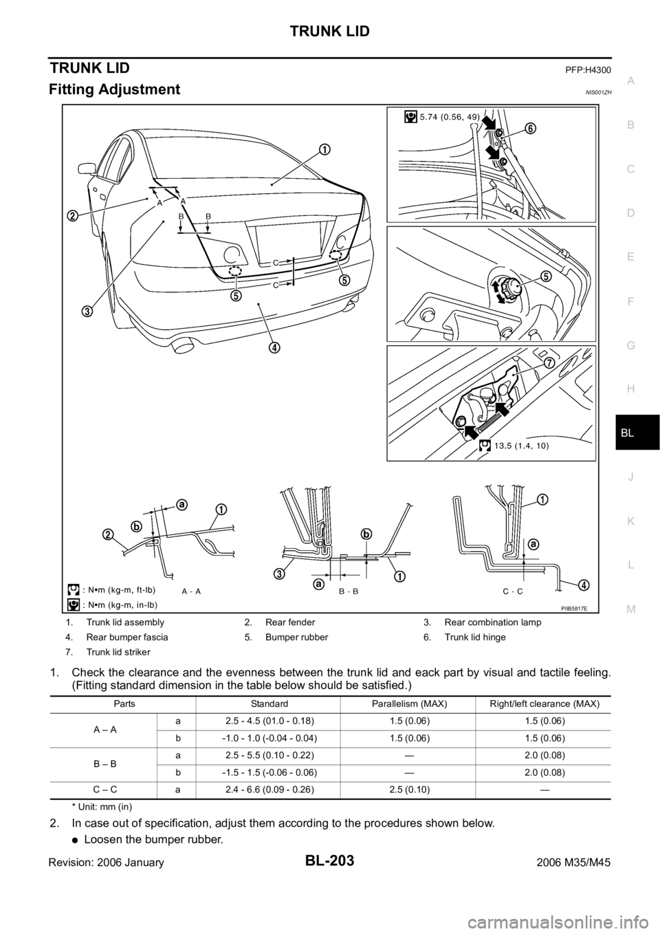
1. Check the clearance and the evenness between the trunk lid and eack part by visual and tactile feeling.
(Fitting standard dimension in the table below should be satisfied.)
* Unit: mm (in)
2. In case out of specification, adjust them according to the procedures shown below.
Loosen the bumper rubber.
1. Trunk lid assembly 2. Rear fender 3. Rear combination lamp
4. Rear bumper fascia 5. Bumper rubber 6. Trunk lid hinge
7. Trunk lid striker
Parts Standard Parallelism (MAX) Right/left clearance (MAX)
A – Aa 2.5 - 4.5 (01.0 - 0.18) 1.5 (0.06) 1.5 (0.06)
b -1.0 - 1.0 (-0.04 - 0.04) 1.5 (0.06) 1.5 (0.06)
B – Ba 2.5 - 5.5 (0.10 - 0.22) — 2.0 (0.08)
b -1.5 - 1.5 (-0.06 - 0.06) — 2.0 (0.08)
C – C a 2.4 - 6.6 (0.09 - 0.26) 2.5 (0.10) —
PIIB5817E
Page 1143 of 5621
BL-204
TRUNK LID
Revision: 2006 January2006 M35/M45
Loosen the striker mounting bolts.
Lift up the trunk lid approx. 100 - 150 mm (3.94 - 5.91 in) height then close it lightly and make sure it
engaged firmly with the trunk lid closed.
Check the clearance and evenness.
Finally tighten the trunk lid striker.
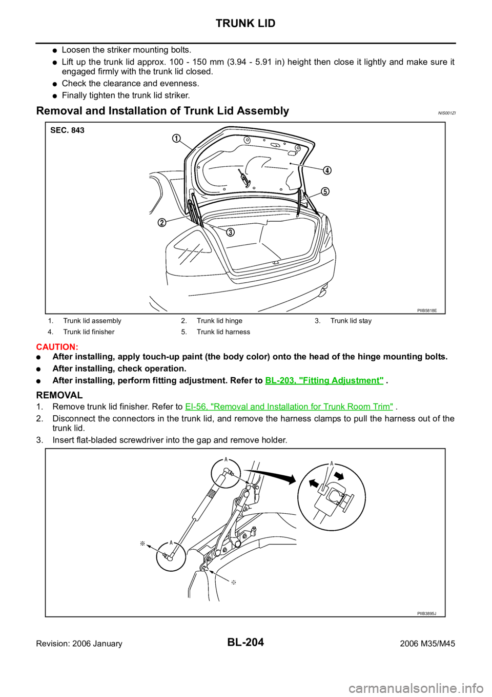
Removal and Installation of Trunk Lid AssemblyNIS001ZI
CAUTION:
After installing, apply touch-up paint (the body color) onto the head of the hinge mounting bolts.
After installing, check operation.
After installing, perform fitting adjustment. Refer to BL-203, "Fitting Adjustment" .
REMOVAL
1. Remove trunk lid finisher. Refer to EI-56, "Removal and Installation for Trunk Room Trim" .
2. Disconnect the connectors in the trunk lid, and remove the harness clamps to pull the harness out of the
trunk lid.
3. Insert flat-bladed screwdriver into the gap and remove holder.
1. Trunk lid assembly 2. Trunk lid hinge 3. Trunk lid stay
4. Trunk lid finisher 5. Trunk lid harness
PIIB5818E
PIIB3895J