Page 1049 of 5621
BL-110
INTELLIGENT KEY SYSTEM
Revision: 2006 January2006 M35/M45
Check Outside Key Antenna (Trunk Room)NIS001XV
1. CHECK OUTSIDE KEY ANTENNA FUNCTION
With CONSULT-II
1. Check the operation with (“ANTENNA”) in the ACTIVE TEST.
2. Touch “BD/TR ANT” on screen.
3. Carry the Intelligent Key into the antenna detection area.
Do the hazard lamps flash?
Yes >> Outside key antenna (trunk room) is OK.
No >> GO TO 2.
2. CHECK OUTSIDE KEY ANTENNA INPUT SIGNAL 1
1. Turn ignition switch OFF.
2. Check signal between Intelligent Key unit connector and ground with oscilloscope.
OK or NG
OK >> Check the condition of harness and connector.
NG >> GO TO 3.
Test item Corresponding antenna
BD/TR ANT Outside key antenna trunk room
PIIB6345E
Te r m i n a l s
ConditionSignal
(Reference value.) (+)
(–) Intelligent
Key unit
connectorTerminal
M33 69 GroundTrunk
request
switch is
pushed
PIIB6348E
SIIA1910J
Page 1050 of 5621
INTELLIGENT KEY SYSTEM
BL-111
C
D
E
F
G
H
J
K
L
MA
B
BL
Revision: 2006 January2006 M35/M45
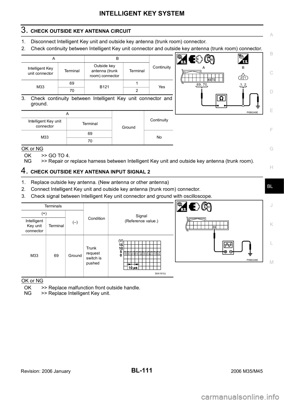
3. CHECK OUTSIDE KEY ANTENNA CIRCUIT
1. Disconnect Intelligent Key unit and outside key antenna (trunk room) connector.
2. Check continuity between Intelligent Key unit connector and outside key antenna (trunk room) connector.
3. Check continuity between Intelligent Key unit connector and
ground.
OK or NG
OK >> GO TO 4.
NG >> Repair or replace harness between Intelligent Key unit and outside key antenna (trunk room).
4. CHECK OUTSIDE KEY ANTENNA INPUT SIGNAL 2
1. Replace outside key antenna. (New antenna or other antenna)
2. Connect Intelligent Key unit and outside key antenna (trunk room) connector.
3. Check signal between Intelligent Key unit connector and ground with oscilloscope.
OK or NG
OK >> Replace malfunction front outside handle.
NG >> Replace Intelligent Key unit.
AB
Continuity
Intelligent Key
unit connectorTerminalOutside key
antenna (trunk
room) connectorTerminal
M3369
B1211
Ye s
70 2
A
GroundContinuity
Intelligent Key unit
connectorTerminal
M3369
No
70
PIIB6349E
Te r m i n a l s
ConditionSignal
(Reference value.) (+)
(–) Intelligent
Key unit
connectorTerminal
M33 69 GroundTrunk
request
switch is
pushed
PIIB6348E
SIIA1910J
Page 1051 of 5621
BL-112
INTELLIGENT KEY SYSTEM
Revision: 2006 January2006 M35/M45
Check Inside Key AntennaNIS001XW
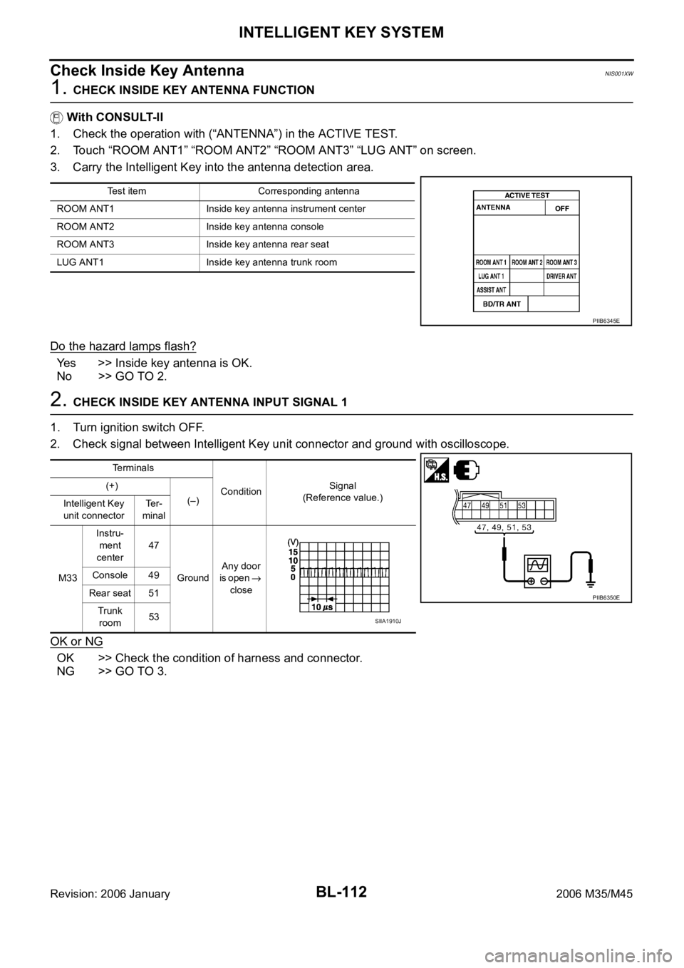
1. CHECK INSIDE KEY ANTENNA FUNCTION
With CONSULT-II
1. Check the operation with (“ANTENNA”) in the ACTIVE TEST.
2. Touch “ROOM ANT1” “ROOM ANT2” “ROOM ANT3” “LUG ANT” on screen.
3. Carry the Intelligent Key into the antenna detection area.
Do the hazard lamps flash?
Yes >> Inside key antenna is OK.
No >> GO TO 2.
2. CHECK INSIDE KEY ANTENNA INPUT SIGNAL 1
1. Turn ignition switch OFF.
2. Check signal between Intelligent Key unit connector and ground with oscilloscope.
OK or NG
OK >> Check the condition of harness and connector.
NG >> GO TO 3.
Test item Corresponding antenna
ROOM ANT1 Inside key antenna instrument center
ROOM ANT2 Inside key antenna console
ROOM ANT3 Inside key antenna rear seat
LUG ANT1 Inside key antenna trunk room
PIIB6345E
Terminals
ConditionSignal
(Reference value.) (+)
(–)
Intelligent Key
unit connectorTe r -
minal
M33Instru-
ment
center47
GroundAny door
is open
close Console 49
Rear seat 51
Trunk
room53
PIIB6350E
SIIA1910J
Page 1052 of 5621
INTELLIGENT KEY SYSTEM
BL-113
C
D
E
F
G
H
J
K
L
MA
B
BL
Revision: 2006 January2006 M35/M45
3. CHECK INSIDE KEY ANTENNA CIRCUIT
1. Disconnect Intelligent Key unit and inside key antenna connector.
2. Check continuity between Intelligent Key unit connector and inside key antenna connector.
3. Check continuity between Intelligent Key unit connector and ground.
OK or NG
OK >> GO TO 4.
NG >> Repair or replace harness between Intelligent Key unit and inside key antenna.
AB
Continuity
Intelligent Key
unit connectorTerminalInside key antenna
connectorTerminal
M3347
M83Instrument
center1
Ye s 48 2
49
M142 Console1
50 2
51
B45 Rear seat1
52 2
53
B132 Trunk room1
54 2
A
GroundContinuity
Intelligent Key unit
connectorTerminal
M33Instrument center47
No 48
Console49
50
Rear seat51
52
Trunk room53
54
PIIB6351E
Page 1053 of 5621
BL-114
INTELLIGENT KEY SYSTEM
Revision: 2006 January2006 M35/M45
4. CHECK INDE KEY ANTENNA INPUT SIGNAL 2
1. Replace inside key antenna. (New antenna or other antenna)
2. Connect Intelligent Key unit and inside key antenna connector.
3. Check signal between Intelligent Key unit connector and ground with oscilloscope.
OK or NG
OK >> Replace malfunction inside key antenna.
NG >> Replace Intelligent Key unit.
Terminals
ConditionSignal
(Reference value.) (+)
(–)
Intelligent Key
unit connectorTe r -
minal
M33Instru-
ment
center47
GroundAny door
is open
close Console 49
Rear seat 51
Trunk
room53
PIIB6350E
SIIA1910J
Page 1060 of 5621
INTELLIGENT KEY SYSTEM
BL-121
C
D
E
F
G
H
J
K
L
MA
B
BL
Revision: 2006 January2006 M35/M45
Check Trunk Lid Opener Cancel SwitchNIS001Y0
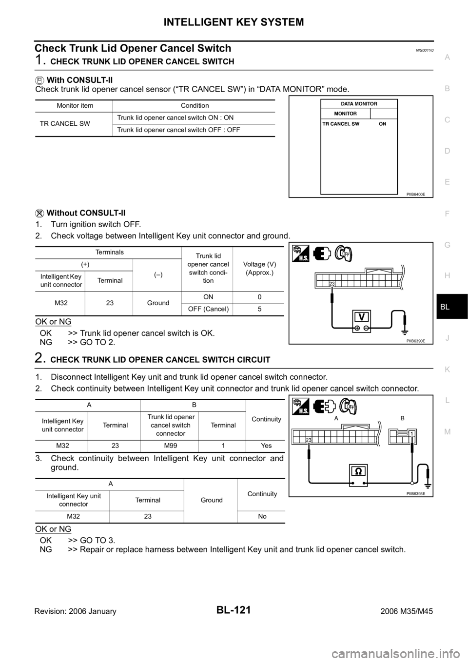
1. CHECK TRUNK LID OPENER CANCEL SWITCH
With CONSULT-II
Check trunk lid opener cancel sensor (“TR CANCEL SW”) in “DATA MONITOR” mode.
Without CONSULT-II
1. Turn ignition switch OFF.
2. Check voltage between Intelligent Key unit connector and ground.
OK or NG
OK >> Trunk lid opener cancel switch is OK.
NG >> GO TO 2.
2. CHECK TRUNK LID OPENER CANCEL SWITCH CIRCUIT
1. Disconnect Intelligent Key unit and trunk lid opener cancel switch connector.
2. Check continuity between Intelligent Key unit connector and trunk lid opener cancel switch connector.
3. Check continuity between Intelligent Key unit connector and
ground.
OK or NG
OK >> GO TO 3.
NG >> Repair or replace harness between Intelligent Key unit and trunk lid opener cancel switch.
Monitor item Condition
TR CANCEL SWTrunk lid opener cancel switch ON : ON
Trunk lid opener cancel switch OFF : OFF
PIIB6400E
Terminals
Trunk lid
opener cancel
switch condi-
tionVoltage (V)
(Approx.) (+)
(–)
Intelligent Key
unit connectorTerminal
M32 23 GroundON 0
OFF (Cancel) 5
PIIB6390E
AB
Continuity
Intelligent Key
unit connectorTe r m i n a l Trunk lid opener
cancel switch
connectorTerminal
M32 23 M99 1 Yes
A
GroundContinuity
Intelligent Key unit
connectorTerminal
M32 23 No
PIIB6393E
Page 1061 of 5621
BL-122
INTELLIGENT KEY SYSTEM
Revision: 2006 January2006 M35/M45
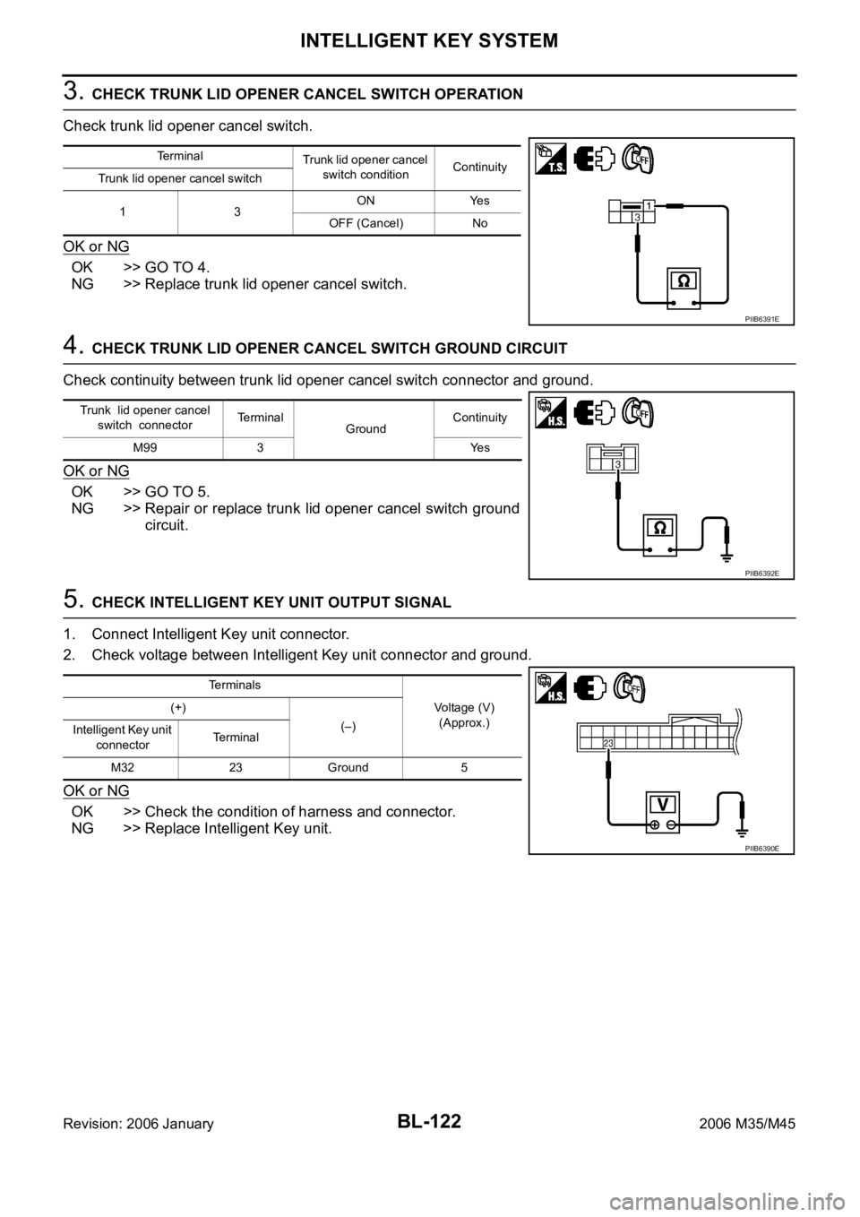
3. CHECK TRUNK LID OPENER CANCEL SWITCH OPERATION
Check trunk lid opener cancel switch.
OK or NG
OK >> GO TO 4.
NG >> Replace trunk lid opener cancel switch.
4. CHECK TRUNK LID OPENER CANCEL SWITCH GROUND CIRCUIT
Check continuity between trunk lid opener cancel switch connector and ground.
OK or NG
OK >> GO TO 5.
NG >> Repair or replace trunk lid opener cancel switch ground
circuit.
5. CHECK INTELLIGENT KEY UNIT OUTPUT SIGNAL
1. Connect Intelligent Key unit connector.
2. Check voltage between Intelligent Key unit connector and ground.
OK or NG
OK >> Check the condition of harness and connector.
NG >> Replace Intelligent Key unit.
Terminal
Trunk lid opener cancel
switch conditionContinuity
Trunk lid opener cancel switch
13ON Yes
OFF (Cancel) No
PIIB6391E
Trunk lid opener cancel
switch connectorTerminal
GroundContinuity
M99 3 Yes
PIIB6392E
Terminals
Voltage (V)
(Approx.) (+)
(–)
Intelligent Key unit
connectorTerminal
M32 23 Ground 5
PIIB6390E
Page 1085 of 5621
BL-146
INTELLIGENT KEY SYSTEM/ENGINE START FUNCTION
Revision: 2006 January2006 M35/M45
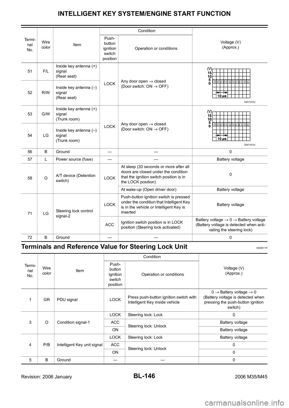
Terminals and Reference Value for Steering Lock UnitNIS001YF
51 F/LInside key antenna (+)
signal
(Rear seat)
LOCKAny door open
closed
(Door switch: ON
OFF)
52 R/WInside key antenna (–)
signal
(Rear seat)
53 G/WInside key antenna (+)
signal
(Trunk room)
LOCKAny door open
closed
(Door switch: ON
OFF)
54 LGInside key antenna (–)
signal
(Trunk room)
56 B Ground — — 0
57 L Power source (fuse) — — Battery voltage
58 OA/T device (Detention
switch)LOCKAt sleep (30 seconds or more after all
doors are closed under the condition
that the ignition switch position is in
the LOCK position)0
At wake-up (Open driver door) Battery voltage
71 LGSteering lock control
signal-2LOCKPush-button ignition switch is pressed
under the condition that Intelligent Key
is in the vehicle or Intelligent Key is
insertedBattery voltage
ACCIgnition switch position is in LOCK
position (Steering lock activated)Battery voltage
0 Battery voltage
(Battery voltage is detected when acti-
vating the steering lock)
72 B Ground — — 0 Te r m i -
nal
No.Wire
colorItemCondition
Voltage (V)
(Approx.) Push-
button
ignition
switch
positionOperation or conditions
SIIA1910J
SIIA1910J
Te r m i -
nal
No.Wire
colorItemCondition
Voltage (V)
(Approx.) Push-
button
ignition
switch
positionOperation or conditions
1 GR PDU signal LOCKPress push-button ignition switch with
Intelligent Key inside vehicle0
Battery voltage 0
(Battery voltage is detected when
pressing the push-button ignition
switch)
3 O Condition signal-1LOCK Steering lock: Lock 0
ACC
Steering lock: UnlockBattery voltage
ON Battery voltage
4 P/B Intelligent Key unit signalLOCK Steering lock: Lock Battery voltage
ACC
Steering lock: Unlock0
ON 0
5 B Ground — — 0