Page 3031 of 5621
EI-26
ROOF SIDE MOLDING
Revision: 2006 January2006 M35/M45
INSTALLATION
1. Place roof side molding on roof groove, and then insert the end into front fender.
2. Align roof side molding clips (molding side) (2),(3), and (4) of front pillar with fastener position, and then
insert roof side molding clip (molding side) (1).
3. Insert roof side molding clips (molding side) of front pillar in order of (2) to (4) into molding fastener.
4. Insert body side outer clips of roof in the order of (5) to (9).
5. Insert rear end of roof side molding into trunk lid.
6. Temporarily set roof side molding clips (molding side) of rear pillar on fasteners and insert them in the
order of (10) to (13).
CAUTION:
Be careful not to damage the body.
PIIB4179J
Page 3038 of 5621

TRUNK LID FINISHER
EI-33
C
D
E
F
G
H
J
K
L
MA
B
EI
Revision: 2006 January2006 M35/M45
TRUNK LID FINISHERPFP:84810
Removal and InstallationNIS0024T
REMOVAL
1. Fully open trunk lid.
2. Remove trunk lid finisher inner. Refer to EI-57, "
REMOVAL AND INSTALLATION OF TRUNK LID FIN-
ISHER INNER" .
3. Remove trunk lid finisher upper mounting nuts.
4. Disconnect back lamp, license lamp and trunk opener switch harness connector.
5. Remove double-faced adhesive tapes with (wide) plastic spatula.Disconnect clips and remove trunk lid
finisher outer.
INSTALLATION
Install in the reverse order of removal.
CAUTION:
Replace double-faced adhesive tape on back of finisher with a new tape if trunk lid finisher outer is
reused.
Remove double-faced adhesive tape remaining on body and back of finisher using double-faced
adhesive tape remover when removing finisher outer.
Install after cleaning adhesive parts of body side and back of finisher outer.
Do not wash the vehicle within 24 hours after installing so as to keep adhesive.
1. Trunk lid finisher outer
PIIB4516E
Page 3049 of 5621
EI-44
SUNSHADE
Revision: 2006 January2006 M35/M45
SUNSHADEPFP:97580
Component Parts and Harness Connector LocationNIS0024Y
PIIB5864E
1. Fuse block (J/B) 2. Back-up lamp relay E19 3.Rear sunshade cancel relay B141
(View with the trunk side finisher RH
removed)
4.Rear sunshade unit (With built-in
motor) B122
(View with the rear parcel shelf fin-
isher removed)5.a: Rear sunshade front switch M137
b: Rear control cancel switch M1516. Rear sunshade rear switch B557
Page 3061 of 5621
EI-56
TRUNK ROOM TRIM & TRUNK LID FINISHER
Revision: 2006 January2006 M35/M45
TRUNK ROOM TRIM & TRUNK LID FINISHERPFP:84920
Removal and Installation for Trunk Room TrimNIS00254
1. Trunk rear plate 2. Trunk front finisher 3. Trunk side finisher (LH)
4. Trunk side finisher (RH) 5. Trunk floor carpet 6. Trunk floor carpet (LH)
7. Trunk floor carpet (RH) 8. Trunk side box
(for temper tire models)9. Rear seatback finisher
10. Trunk room lamp 11. Trunk floor felt (LH) 12. Trunk floor felt (RH)
13. Trunk floor spacer (LH)
(for sport models)14. Trunk floor spacer (RH)
(for sport models)15. Trunk net
Metal clip
PIIB6290E
Page 3062 of 5621

TRUNK ROOM TRIM & TRUNK LID FINISHER
EI-57
C
D
E
F
G
H
J
K
L
MA
B
EI
Revision: 2006 January2006 M35/M45
REMOVAL
1. Fully open trunk lid assembly.
2. Remove trunk floor carpet.
3. Remove trunk side box. (for temper tire models)
4. Remove trunk floor spacer (LH/RH). (for sport models)
5. Remove trunk room lamp of trunk rear plate, and disconnect trunk room lamp connector.
6. Remove trunk rear plate mounting clips, and the remove trunk rear plate.
7. Remove trunk side finisher mounting clips, and the remove trunk side finisher (LH/RH).
8. Remove rear seatback and rear seat cushion. Refer to SE-172, "
REAR SEAT" .
9. Remove rear seatback finisher mounting clips, and the remove rear seatback finisher.
10. Remove trunk room lamp of trunk front finisher, and disconnect trunk room lamp connector.
11. Remove trunk front finisher mounting clips, and the trunk front finisher.
INSTALLATION
Install in the reverse order of removal.
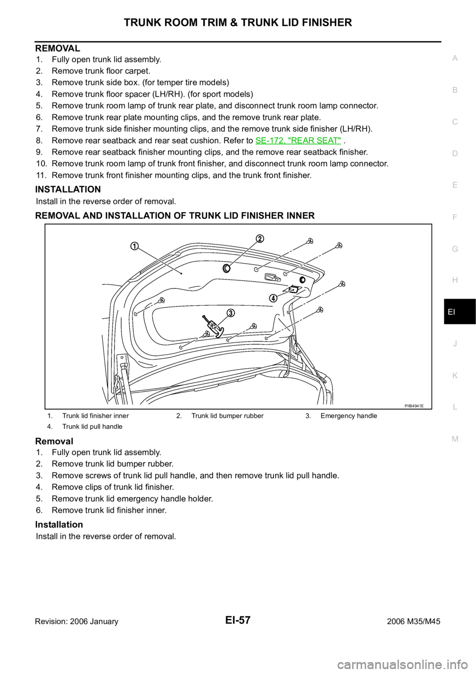
REMOVAL AND INSTALLATION OF TRUNK LID FINISHER INNER
Removal
1. Fully open trunk lid assembly.
2. Remove trunk lid bumper rubber.
3. Remove screws of trunk lid pull handle, and then remove trunk lid pull handle.
4. Remove clips of trunk lid finisher.
5. Remove trunk lid emergency handle holder.
6. Remove trunk lid finisher inner.
Installation
Install in the reverse order of removal.
1. Trunk lid finisher inner 2. Trunk lid bumper rubber 3. Emergency handle
4. Trunk lid pull handle
PIIB4941E
Page 3063 of 5621
EI-58
TRUNK ROOM TRIM & TRUNK LID FINISHER
Revision: 2006 January2006 M35/M45
Page 3483 of 5621
GI-20
HOW TO USE THIS MANUAL
Revision: 2006 January2006 M35/M45
Harness Indication
Letter designations next to test meter probe indicate harness
(connector) wire color.
Connector numbers in a single circle M33 indicate harness con-
nectors.
Component Indication
Connector numbers in a double circle F211 indicate component connectors.
Switch Positions
Switches are shown in wiring diagrams as if the vehicle is in the “normal” condition.
A vehicle is in the “normal” condition when:
ignition switch is “OFF”,
doors, hood and trunk lid/back door are closed,
pedals are not depressed, and
parking brake is released.
AGI070
SGI860
Page 3520 of 5621

GW-1
GLASSES, WINDOW SYSTEM & MIRRORS
I BODY
CONTENTS
C
D
E
F
G
H
J
K
L
M
SECTION GW
A
B
GW
Revision: 2006 January2006 M35/M45
GLASSES, WINDOW SYSTEM & MIRRORS
PRECAUTIONS .......................................................... 3
Precautions for Supplemental Restraint System
(SRS) “AIR BAG” and “SEAT BELT PRE-TEN-
SIONER” .................................................................. 3
Precautions for Procedures without Cowl Top Cover ..... 3
Handling for Adhesive and Primer ........................... 3
PREPARATION ........................................................... 4
Special Service Tools ............................................... 4
Commercial Service Tools ........................................ 4
SQUEAK AND RATTLE TROUBLE DIAGNOSES ..... 5
Work Flow ................................................................ 5
CUSTOMER INTERVIEW ..................................... 5
DUPLICATE THE NOISE AND TEST DRIVE ....... 6
CHECK RELATED SERVICE BULLETINS ........... 6
LOCATE THE NOISE AND IDENTIFY THE
ROOT CAUSE ...................................................... 6
REPAIR THE CAUSE ........................................... 6
CONFIRM THE REPAIR ....................................... 7
Generic Squeak and Rattle Troubleshooting ........... 7
INSTRUMENT PANEL .......................................... 7
CENTER CONSOLE ............................................. 7
DOORS ................................................................. 7
TRUNK .................................................................. 8
SUNROOF/HEADLINING ..................................... 8
SEATS ................................................................... 8
UNDERHOOD ....................................................... 8
Diagnostic Worksheet .............................................. 9
WINDSHIELD GLASS ...............................................11
Removal and Installation ......................................... 11
REMOVAL ........................................................
.... 11
INSTALLATION ................................................... 12
POWER WINDOW SYSTEM .................................... 13
Component Parts and Harness Connector Location ... 13
System Description ................................................ 13
MANUAL OPERATION ....................................... 14
AUTO OPERATION ............................................ 16
POWER WINDOW SERIAL LINK ....................... 16
POWER WINDOW LOCK ................................... 16
RETAINED POWER OPERATION ...................... 16ANTI-PINCH SYSTEM ........................................ 17
INITIALIZATION .................................................. 17
FAIL-SAFE CONTROL ........................................ 18
POWER WINDOW CONTROL BY THE KEY
CYLINDER SWITCH ........................................... 18
CAN Communication System Description .............. 19
CAN Communication Unit ....................................... 19
Schematic ............................................................... 20
Wiring Diagram — WINDOW — ............................. 21
Terminal and Reference Value for BCM ................. 27
Terminal and Reference Value for Power Window
Main Switch ............................................................ 28
Terminal and Reference Value for (Front and Rear)
Power Window Sub-Switch .................................... 29
CONSULT-II Function (BCM) ................................. 30
WORK SUPPORT ............................................... 31
DATE MONITOR ................................................. 31
Work Flow ............................................................... 32
Trouble Diagnosis Symptom Chart ......................... 32
BCM Power Supply and Ground Circuit Check ...... 34
Power Window Main Switch Power Supply Circuit
Check ..................................................................... 35
Power Window Sub-Switch (Front Passenger Side)
Power Supply and Ground Circuit Check ............... 36
Power Window Sub-Switch (Rear LH or RH) Power
Supply and Ground Circuit Check .......................... 37
Power Window Motor (Front Driver Side) Circuit
Check ..................................................................... 38
Power Window Motor (Front Passenger Side) Cir-
cuit Check ............................................................... 39
Power Window Motor (Rear LH or RH) Circuit Check ... 40
Encoder Circuit Check (Driver Side) ....................... 42
Encoder Circuit Check (Passenger Side) ............... 45
Encoder Circuit Check (Rear LH or RH) ................. 48
Door Switch Check ..............................................
... 52
Front Door Key Cylinder Switch Check .................. 54
Power Window Serial Link Check (Passenger Side) ... 56
Power Window Serial Link Check (Rear LH or RH) ... 58
Power Window Lock Switch Check ........................ 58