Page 1219 of 4462
![INFINITI FX35 2006 Service Manual WATER PUMP CO-25
[VQ35DE]
C
D E
F
G H
I
J
K L
M A
CO
Revision: 2006 December 2006 FX35/FX45
a. Turn crankshaft pulley clockwise so that timing chain on the tim- ing chain tensioner (prima](/manual-img/42/57019/w960_57019-1218.png "INFINITI FX35 2006 Service Manual WATER PUMP CO-25
[VQ35DE]
C
D E
F
G H
I
J
K L
M A
CO
Revision: 2006 December 2006 FX35/FX45
a. Turn crankshaft pulley clockwise so that timing chain on the tim- ing chain tensioner (prima")
WATER PUMP CO-25
[VQ35DE]
C
D E
F
G H
I
J
K L
M A
CO
Revision: 2006 December 2006 FX35/FX45
a. Turn crankshaft pulley clockwise so that timing chain on the tim- ing chain tensioner (primary) side is loose.
b. Pull plunger stopper tab up (or turn lever downward) so as to remove plunger stopper tab from the ratchet of plunger.
NOTE:
Plunger stopper tab and lever are synchronized.
c. Push plunger into the inside of tensioner body.
d. Hold plunger in the fully compressed position by engaging plunger stopper tab with the tip of ratchet.
e. To secure lever, insert stopper pin through hole of lever into ten- sioner body hole.
�The lever parts and the tab are synchronized. Therefore, the
plunger will be secured under this condition.
NOTE:
Figure shows the example of 1.2 mm (0.047 in) diameter thin screwdriver being used as the stopper pin.
f. Install timing chain tensioner (primary).
�Remove dust and foreign material completely from backside of timing chain tensioner (primary) and
from installation area of rear timing chain case.
g. Remove stopper pin.
h. Make sure again that timing chain and water pump sprocket are engaged.
4. Install chain tensioner cover and water pump cover as follows:
a. Before installing, remove all traces of old liquid gasket from mat- ing surface of water pump cover and chain tensioner cover
using a scraper. Also remove traces of old liquid gasket from the
mating surface of front timing chain case.
PBIC1805E
PBIC3568E
PBIC3577E
SLC446B
Page 1220 of 4462
![INFINITI FX35 2006 Service Manual CO-26
[VQ35DE]
WATER PUMP
Revision: 2006 December 2006 FX35/FX45
b. Apply a continuous bead of liquid gasket with the tube presser [SST: WS39930000 ( — )] to mating surface of chain ten-
sioner cove](/manual-img/42/57019/w960_57019-1219.png "INFINITI FX35 2006 Service Manual CO-26
[VQ35DE]
WATER PUMP
Revision: 2006 December 2006 FX35/FX45
b. Apply a continuous bead of liquid gasket with the tube presser [SST: WS39930000 ( — )] to mating surface of chain ten-
sioner cove")
CO-26
[VQ35DE]
WATER PUMP
Revision: 2006 December 2006 FX35/FX45
b. Apply a continuous bead of liquid gasket with the tube presser [SST: WS39930000 ( — )] to mating surface of chain ten-
sioner cover and water pump cover.
Use Genuine RTV Silicone Sealant or equivalent. Refer to
GI-48, "
RECOMMENDED CHEMICAL PRODUCTS AND
SEALANTS" .
CAUTION:
Attaching should be done within 5 minutes after coating.
c. Tighten mounting bolts.
5. Install water drain plug (front) on water pump side of cylinder block.
�Apply liquid gasket to the thread of water drain plug (front).
Use Genuine RTV Silicone Sealant or equivalent. Refer to GI-48, "
RECOMMENDED CHEMICAL
PRODUCTS AND SEALANTS" .
6. Install in the reverse order of removal for remaining parts.
�After starting engine, let idle for three minutes, then rev engine up to 3,000 rpm under no load to
purge air from the high-pressure chamber of chain tensioner. Engine may produce a rattling
noise. This indicates that air still remains in the chamber and is not a matter of concern.
INSPECTION AFTER INSTALLATION
�Check for leaks of engine coolant using the radiator cap tester adapter [SST: EG17650301 (J33984-A)]
and the radiator cap tester (commercial service tool). Refer to CO-11, "
LEAK CHECK" .
�Start and warm up the engine. Visually make sure that there is no leaks of engine coolant.
PBIC2663E
Page 1221 of 4462
WATER INLET AND THERMOSTAT ASSEMBLY CO-27
[VQ35DE]
C
D E
F
G H
I
J
K L
M A
CO
Revision: 2006 December 2006 FX35/FX45
WATER INLET AND THERMOSTAT ASSEMBLYPFP:21200
ComponentsNBS003K7
Removal and InstallationNBS003K8
REMOVAL
1. Remove front engine undercover using power tool.
2. Drain engine coolant from radiator drain plug at the bottom of radiator, and from water drain plug at the front of cylinder block. Refer to CO-11, "
Changing Engine Coolant" and CO-22, "WATER PUMP" .
CAUTION:
�Perform this step when the engine is cold.
�Do not spill engine coolant on drive belts.
3. Remove air duct (inlet). Refer to EM-17, "
AIR CLEANER AND AIR DUCT" .
4. Disconnect radiator hose (lower) and oil cooler water hose from water inlet and thermostat assembly.
5. Remove water inlet and thermostat assembly. CAUTION:
Do not disassemble water inlet and thermostat assembly.
Replace them as a unit, if necessary.
1. Water inlet and thermostat assembly 2. Gasket
SBIA0483E
SLC962AB
Page 1223 of 4462
![INFINITI FX35 2006 Service Manual WATER OUTLET AND WATER PIPING CO-29
[VQ35DE]
C
D E
F
G H
I
J
K L
M A
CO
Revision: 2006 December 2006 FX35/FX45
WATER OUTLET AND WATER PIPINGPFP:11060
ComponentsNBS003K9
Removal and Install](/manual-img/42/57019/w960_57019-1222.png "INFINITI FX35 2006 Service Manual WATER OUTLET AND WATER PIPING CO-29
[VQ35DE]
C
D E
F
G H
I
J
K L
M A
CO
Revision: 2006 December 2006 FX35/FX45
WATER OUTLET AND WATER PIPINGPFP:11060
ComponentsNBS003K9
Removal and Install")
WATER OUTLET AND WATER PIPING CO-29
[VQ35DE]
C
D E
F
G H
I
J
K L
M A
CO
Revision: 2006 December 2006 FX35/FX45
WATER OUTLET AND WATER PIPINGPFP:11060
ComponentsNBS003K9
Removal and InstallationNBS003KA
REMOVAL
1. Remove front engine undercover with power tool.
2. Drain engine coolant from radiator drain plug at the bottom of radiator, and from water drain plug at the front of cylinder block. Refer to CO-11, "
Changing Engine Coolant" and CO-22, "WATER PUMP" .
CAUTION:
�Perform this step when the engine is cold.
�Do not spill engine coolant on drive belts.
3. Remove engine cover with power tool. Refer to EM-19, "
INTAKE MANIFOLD COLLECTOR" .
4. Remove air duct (inlet), air duct and air cleaner case assembly. Refer to EM-17, "
AIR CLEANER AND AIR
DUCT" .
5. Remove radiator hose (upper) and heater hose.
6. Remove the following parts, when remove water outlet.
�A/T fluid charging pipe; Refer to AT- 2 6 6 , "TRANSMISSION ASSEMBLY" .
�Intake manifold collectors (upper and lower). Refer to EM-19, "INTAKE MANIFOLD COLLECTOR" .
�Rocker cover (right bank). Refer to EM-51, "ROCKER COVER" .
7. Remove engine coolant temperature sensor as necessary. CAUTION:
Be careful not to damage engine coolant temperature sensor.
8. Remove water outlet, heater pipe, water bypass hoses and water pipe.
1. Harness bracket 2. Water hose 3. Water bypass hose
4. Engine coolant temperature sensor 5. Gasket 6. Water outlet
7. Heater hose 8. Water pipe 9. Radiator hose (upper)
10. Heater pipe 11. Washer 12. O-ring
SBIA0484E
Page 1228 of 4462
![INFINITI FX35 2006 Service Manual CO-34
[VK45DE]
OVERHEATING CAUSE ANALYSIS
Revision: 2006 December 2006 FX35/FX45
OVERHEATING CAUSE ANALYSISPFP:00012
Troubleshooting ChartNBS003KF
Symptom Check items
Cooling sys-
tem parts
malfun](/manual-img/42/57019/w960_57019-1227.png "INFINITI FX35 2006 Service Manual CO-34
[VK45DE]
OVERHEATING CAUSE ANALYSIS
Revision: 2006 December 2006 FX35/FX45
OVERHEATING CAUSE ANALYSISPFP:00012
Troubleshooting ChartNBS003KF
Symptom Check items
Cooling sys-
tem parts
malfun")
CO-34
[VK45DE]
OVERHEATING CAUSE ANALYSIS
Revision: 2006 December 2006 FX35/FX45
OVERHEATING CAUSE ANALYSISPFP:00012
Troubleshooting ChartNBS003KF
Symptom Check items
Cooling sys-
tem parts
malfunction Poor heat transfer
Water pump malfunction Worn or loose drive belt
—
Thermostat and water con-
trol valve stuck closed —
Damaged fins Dust contamination or
paper clogging
Physical damage
Clogged radiator cooling
tube Excess foreign material
(rust, dirt, sand, etc.)
Reduced air flow Cooling fan does not oper-
ate
Fan assembly —
High resistance to fan rota-
tion
Damaged fan blades
Damaged radiator shroud — — —
Improper engine coolant
mixture ratio —— —
Poor engine coolant quality — Engine coolant density —
Insufficient engine coolant Engine coolant leaks Cooling hose
Loose clamp
Cracked hose
Water pump Poor sealing
Radiator cap Loose
Poor sealing
Radiator O-ring for damage, deterio-
ration or improper fitting
Cracked radiator tank
Cracked radiator core
Reservoir tank Cracked reservoir tank
Overflowing reservoir tank Exhaust gas leaks into
cooling system Cylinder head deterioration
Cylinder head gasket dete-
rioration
Page 1243 of 4462
![INFINITI FX35 2006 Service Manual COOLING FAN CO-49
[VK45DE]
C
D E
F
G H
I
J
K L
M A
CO
Revision: 2006 December 2006 FX35/FX45
COOLING FANPFP:21140
Components (Crankshaft Driven type)NBS005RY
Removal and InstallationNBS003](/manual-img/42/57019/w960_57019-1242.png "INFINITI FX35 2006 Service Manual COOLING FAN CO-49
[VK45DE]
C
D E
F
G H
I
J
K L
M A
CO
Revision: 2006 December 2006 FX35/FX45
COOLING FANPFP:21140
Components (Crankshaft Driven type)NBS005RY
Removal and InstallationNBS003")
COOLING FAN CO-49
[VK45DE]
C
D E
F
G H
I
J
K L
M A
CO
Revision: 2006 December 2006 FX35/FX45
COOLING FANPFP:21140
Components (Crankshaft Driven type)NBS005RY
Removal and InstallationNBS003KO
REMOVAL
1. Remove air duct (inlet). Refer to EM-177, "AIR CLEANER AND AIR DUCT" .
2. Remove engine front undercover with power tool.
3. Remove radiator shroud (lower). Refer to CO-41, "
RADIATOR" .
4. Remove drive belts. Refer to EM-174, "
DRIVE BELTS" .
5. Remove fan coupling and cooling fan assembly. CAUTION:
Do not damage or scratch radiator core when removing.
6. Remove cooling fan from fan coupling.
INSPECTION AFTER REMOVAL
Fan Coupling
Inspect fan coupling for oil leakage and bimetal conditions.
�If anything is found, replace fan coupling.
Cooling Fan
Inspect cooling fan for crack or unusual bend.
�If anything is found, replace cooling fan.
INSTALLATION
Note the following, install in the reverse order of removal.
�Install cooling fan with its front mark “F” facing front of vehicle. Refer to CO-49, "Removal and Installation"
.
1. Cooling fan 2. Fan coupling 3. Fan pulley
4. Water pump
PBIC1537E
SLC072
Page 1245 of 4462
![INFINITI FX35 2006 Service Manual WATER PUMP CO-51
[VK45DE]
C
D E
F
G H
I
J
K L
M A
CO
Revision: 2006 December 2006 FX35/FX45
WAT E R P U MPPFP:21020
ComponentsNBS005S0
Removal and InstallationNBS003KR
CAUTION:
�When remo](/manual-img/42/57019/w960_57019-1244.png "INFINITI FX35 2006 Service Manual WATER PUMP CO-51
[VK45DE]
C
D E
F
G H
I
J
K L
M A
CO
Revision: 2006 December 2006 FX35/FX45
WAT E R P U MPPFP:21020
ComponentsNBS005S0
Removal and InstallationNBS003KR
CAUTION:
�When remo")
WATER PUMP CO-51
[VK45DE]
C
D E
F
G H
I
J
K L
M A
CO
Revision: 2006 December 2006 FX35/FX45
WAT E R P U MPPFP:21020
ComponentsNBS005S0
Removal and InstallationNBS003KR
CAUTION:
�When removing water pump, be careful not to get engine coolant on drive belts.
�Water pump can not be disassembled and should be replaced as a unit.
�After installing water pump, connect hose and clamp securely, then check for leaks using radiator
cap tester (commercial service tool) and radiator cap tester adapter [SST: EG17650301 (J33984-
A)].
REMOVAL
1. Drain engine coolant from drain plugs on radiator and both side of cylinder block. Refer to CO-38, "Chang-
ing Engine Coolant" and EM-249, "DISASSEMBLY" .
CAUTION:
�Perform this step when engine is cold.
�Do not spill engine coolant on drive belts.
2. Remove following parts:
�Engine front undercover
�Air duct (inlet); Refer to EM-177, "AIR CLEANER AND AIR DUCT" .
�Alternator, water pump and A/C compressor belt; Refer to EM-174, "DRIVE BELTS" .
3. Remove fan coupling with cooling fan, and then water pump pulley.
4. Remove water pump.
�Engine coolant will leak from cylinder block, so have a receptacle ready under vehicle.
CAUTION:
�Handle the water pump vane so that it does not contact any other parts.
�Do not disassemble water pump.
1. Water pump pulley 2. Water pump 3. Gasket
PBIC1538E
Page 1246 of 4462
CO-52
[VK45DE]
WATER PUMP
Revision: 2006 December 2006 FX35/FX45
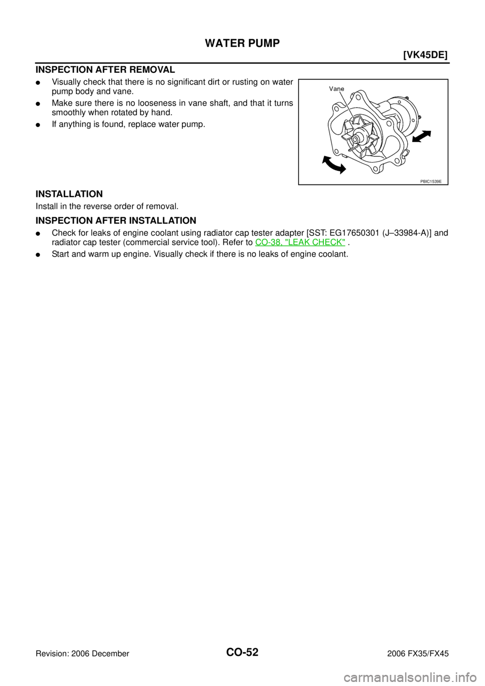
INSPECTION AFTER REMOVAL
�Visually check that there is no significant dirt or rusting on water
pump body and vane.
�Make sure there is no looseness in vane shaft, and that it turns
smoothly when rotated by hand.
�If anything is found, replace water pump.
INSTALLATION
Install in the reverse order of removal.
INSPECTION AFTER INSTALLATION
�Check for leaks of engine coolant using radiator cap tester adapter [SST: EG17650301 (J–33984-A)] and
radiator cap tester (commercial service tool). Refer to CO-38, "
LEAK CHECK" .
�Start and warm up engine. Visually check if there is no leaks of engine coolant.
PBIC1539E
![INFINITI FX35 2006 Service Manual WATER INLET AND THERMOSTAT ASSEMBLY CO-27
[VQ35DE]
C
D E
F
G H
I
J
K L
M A
CO
Revision: 2006 December 2006 FX35/FX45
WATER INLET AND THERMOSTAT ASSEMBLYPFP:21200
ComponentsNBS003K7
Removal](/manual-img/42/57019/w960_57019-1220.png "INFINITI FX35 2006 Service Manual WATER INLET AND THERMOSTAT ASSEMBLY CO-27
[VQ35DE]
C
D E
F
G H
I
J
K L
M A
CO
Revision: 2006 December 2006 FX35/FX45
WATER INLET AND THERMOSTAT ASSEMBLYPFP:21200
ComponentsNBS003K7
Removal")