Page 154 of 425
Figure 8.39 Valve fixing plug and pin
Figure 8.40 Torque converter release ball and spring
Page 156 of 425
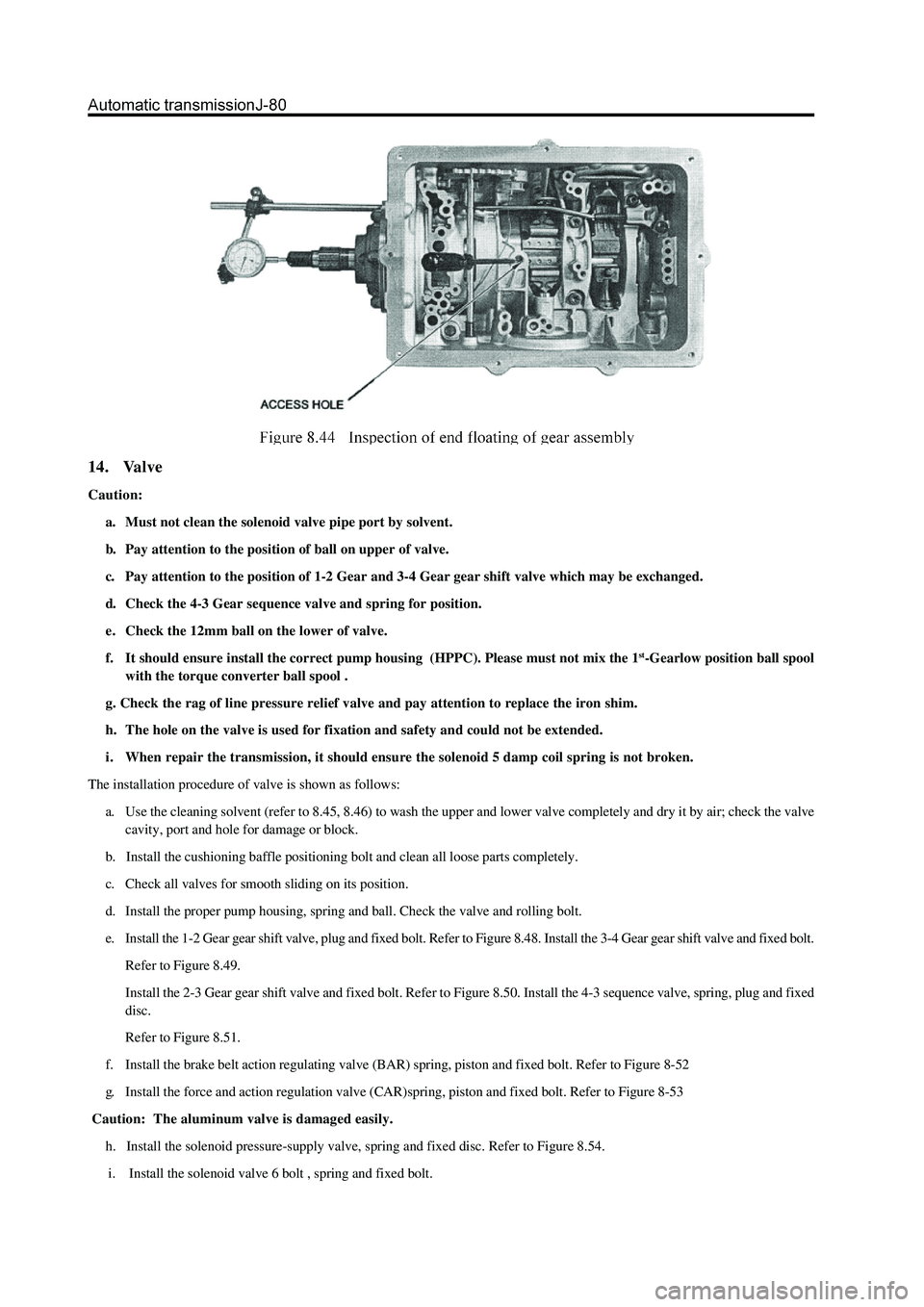
14. Valve
Caution:
a. Must not clean the solenoid valve pipe port by solvent.
b. Pay attention to the position of ball on upper of valve.
c. Pay attention to the position of 1-2 Gear and 3-4 Gear gear shift valve which may be exchanged.
d. Check the 4-3 Gear sequence valve and spring for position.
e. Check the 12mm ball on the lower of valve.
f. It should ensure install the correct pump housing (HPPC). Please must not mix the 1
st-Gearlow position ball spool
with the torque converter ball spool .
g. Check the rag of line pressure relief valve and pay attention to replace the iron shim.
h. The hole on the valve is used for fixation and safety and could not be extended.
i . When repair the transmission, it should ensure the solenoid 5 damp coil spring is not broken.
The installation procedure of valve is shown as follows:
a. Use the cleaning solvent (refer to 8.45, 8.46) to wash the upper and lower valve completely and dry it by air; check the valve
cavity, port and hole for damage or block.
b. Install the cushioning baffle positioning bolt and clean all loose parts completely.
c. Check all valves for smooth sliding on its position.
d. Install the proper pump housing, spring and ball. Check the valve and rolling bolt.
e. Install the 1-2 Gear gear shift valve, plug and fixed bolt. Refer to Figure 8.48. Install the 3-4 Gear gear shift valve and fixed bolt.
Refer to Figure 8.49.
Install the 2-3 Gear gear shift valve and fixed bolt. Refer to Figure 8.50. Install the 4-3 sequence valve, spring, plug and fixed
disc.
Refer to Figure 8.51.
f. Install the brake belt action regulating valve (BAR) spring, piston and fixed bolt. Refer to Figure 8-52
g. Install the force and action regulation valve (CAR)spring, piston and fixed bolt. Refer to Figure 8-53
Caution: The aluminum valve is damaged easily.
h. Install the solenoid pressure-supply valve, spring and fixed disc. Refer to Figure 8.54.
i. Install the solenoid valve 6 bolt , spring and fixed bolt.
Page 160 of 425
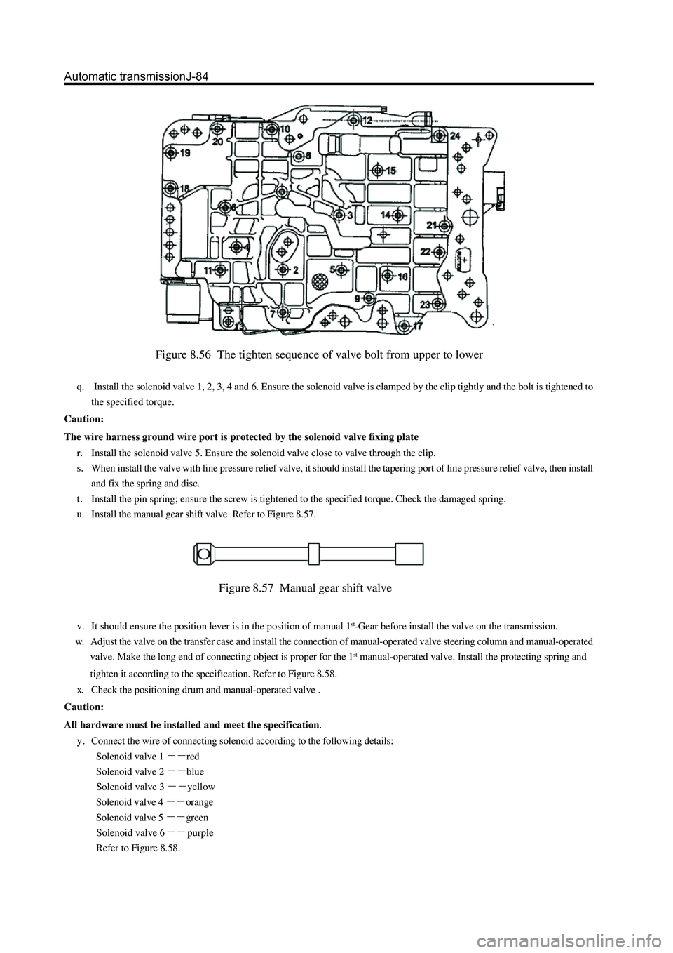
Figure 8.56 The tighten sequence of valve bolt from upper to lower
q. Install the solenoid valve 1, 2, 3, 4 and 6. Ensure the solenoid valve is clamped by the clip tightly and the bolt is tightened to
the specified torque.
Caution:
The wire harness ground wire port is protected by the solenoid valve fixing plate
r. Install the solenoid valve 5. Ensure the solenoid valve close to valve through the clip.
s. When install the valve with line pressure relief valve, it should install the tapering port of line pressure relief valve, then install
and fix the spring and disc.
t . Install the pin spring; ensure the screw is tightened to the specified torque. Check the damaged spring.
u. Install the manual gear shift valve .Refer to Figure 8.57.
Figure 8.57 Manual gear shift valve
v. It should ensure the position lever is in the position of manual 1st-Gear before install the valve on the transmission.
w. Adjust the valve on the transfer case and install the connection of manual-operated valve steering column and manual-operated
valve. Make the long end of connecting object is proper for the 1
st manual-operated valve. Install the protecting spring and
tighten it according to the specification. Refer to Figure 8.58.
x. Check the positioning drum and manual-operated valve .
Caution:
All hardware must be installed and meet the specification.
y . Connect the wire of connecting solenoid according to the following details:
Solenoid valve 1
red
Solenoid valve 2
blue
Solenoid valve 3
yellow
Solenoid valve 4
orange
Solenoid valve 5
green
Solenoid valve 6
purple
Refer to Figure 8.58.
Page 163 of 425
f. Make the installation of oil bottom shell is proper for transfer case and the tighten the safety valve according to the
specification and sequence (Refer to Figure 8.61). do not distort it.
16.Torque converter and support sleeve assembly
Install the hydraulic torque converter and housing assembly, the procedure is shown as follows:
a. Install the hydraulic torque converter housing on the main case.
Caution:
All hardware should be installed correctly and comply with the specification.
b. Use the Loctite243 or equivalent to fix the torque converter housing; install and tighten it to standard specification.
c. Install the torque converter; ensure the pump gear sealing is installed correctly.
17. Rear wheel drive mode of output ring flange assembly
Assemble the output shaft assembly, the procedure is shown as follows:
a. Place the paw of transmission operating rod on the parking position and lock the output shaft.
b. Wash the output shaft upper line; use the loctite243 or equivalent.
c. Install and tighten the ring flange, O-ring and nut.
Caution: In the heavy steel slide plate, place the ring flange on the upper nut; avoid the damage of bearing.
d. Tighten the nut on the output shaft
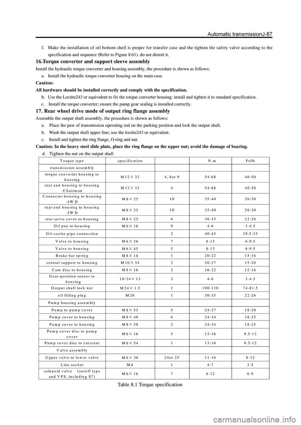
Torque type specification N.m Ft/lb
tra n s m iss io n as se m b ly
torque converter housing to
housing M12×32 4, 8or 9 54-68 40-50
rear end housing to housing
-C h a irm a n M12×32 4 54-68 40-50
C onnector housing to housing
-4 W D M8×25 10 35-40 26-30
rear end housing to housing
-2 W D M8×25 10 35-40 26-30
rear servo cover to housing
M8×25 6 30-35 22-26
O il pan to housing
M6×16 9 4-6 3-4.5
O il cooler pipe connection
2 40-45 29.5-33
V alve to housing
M6×26 7 8-13 6-9.5
V alve to housing
M6×45 5 8-13 6-9.5
B rake bar spring
M8×16 1 20-22 15-16
central support to housing
M10×34 2 20-27 15-20
C am disc to housing
M8×16 2 16-22 12-16
G ear-position sensor to
housing 10-24×13 2 4-6 3-4.5
O utput shaft lock nut
M24×1.5 1 100-110 74-81.5
oil filling plug M 20 1 30-35 22-26
Pump housing assembly
Pump to pump cover
M8×55 5 24-27 18-20
Pum p cover to housing
M8×40 6 24-34 18-25
Pum p cover to housing
M8×58 2 24-34 18-25
Pum p cover disc to pum p
cover M6×16 5 13-16 9.5-12
Pum p cover disc to crescent
M6×54 1 13-16 9.5-12
Valve assem bly
U p p e r v a lv e to lo w e r v a lv e
M6×30 24or 25 11-16 8-12
Line socket M 6 1 4-7 3-5
solenoid valve (on/off type
and VPS, including S7) M6×16 7 8-12 6-9
Table 8.1 Torque specification
Page 166 of 425
O il fillin g procedure
According to the procedure described in 7.2.
Specification and special tools
Type and specification
hydraulic torque converter
maximum torque multiplier factor
179K
stalled speed (80 to 100 ℃ rp m)
(179K torque converter ) Specification
2.00: 1
2090
Gear ratio
First gear
Second gear
Third gear
Fourth gear
Reverse gear
2.393:1
1.450:1
1.000:1
0.677:1
2.093:1
Lubricant
type
dry system
alternative of maintenance Castrol TQ95
9.0 L (approximation)
4.5L (approximation)
Axial movement of gear assembly 0.50-0.65 mm
Fixed pinion axle movement 0.10-0.50 mm
Tab le 9 .1-Type specification
Pressing factor of clutch
0588-000001
C1
structure (friction disk )
steel 5
5 (2)
C2
structure (friction disk )
steel 5
4 (2)
C3
structure (friction disk )
steel 4
4 (2)
C4
structure (friction disk )
steel 3
4 (1)
Table 9.2 Shifting point of clutch assembly details
Page 171 of 425
Front axle propeller shaft (4WD) assembly
Rear axle propeller shaft (4WD) assembly
N m: Specified torque
universal-joint forkfront section of
rear axle propeller
shaft
intermediate sup-
port assembly
universal-
joint fork
shimnut
circlip
cross-axle assembly
rear section assembly of
rear axle propeller shaft
flange forkcirclip
cross-axle assembly
axle tube assembly
front axle drive shaft assembly
N
m: Specified torque
universal-joint fork
circlip
cross-axle
assembly
drive shaft axle
pipe assembly
N
m: Specified torqueflange fork
Page 172 of 425
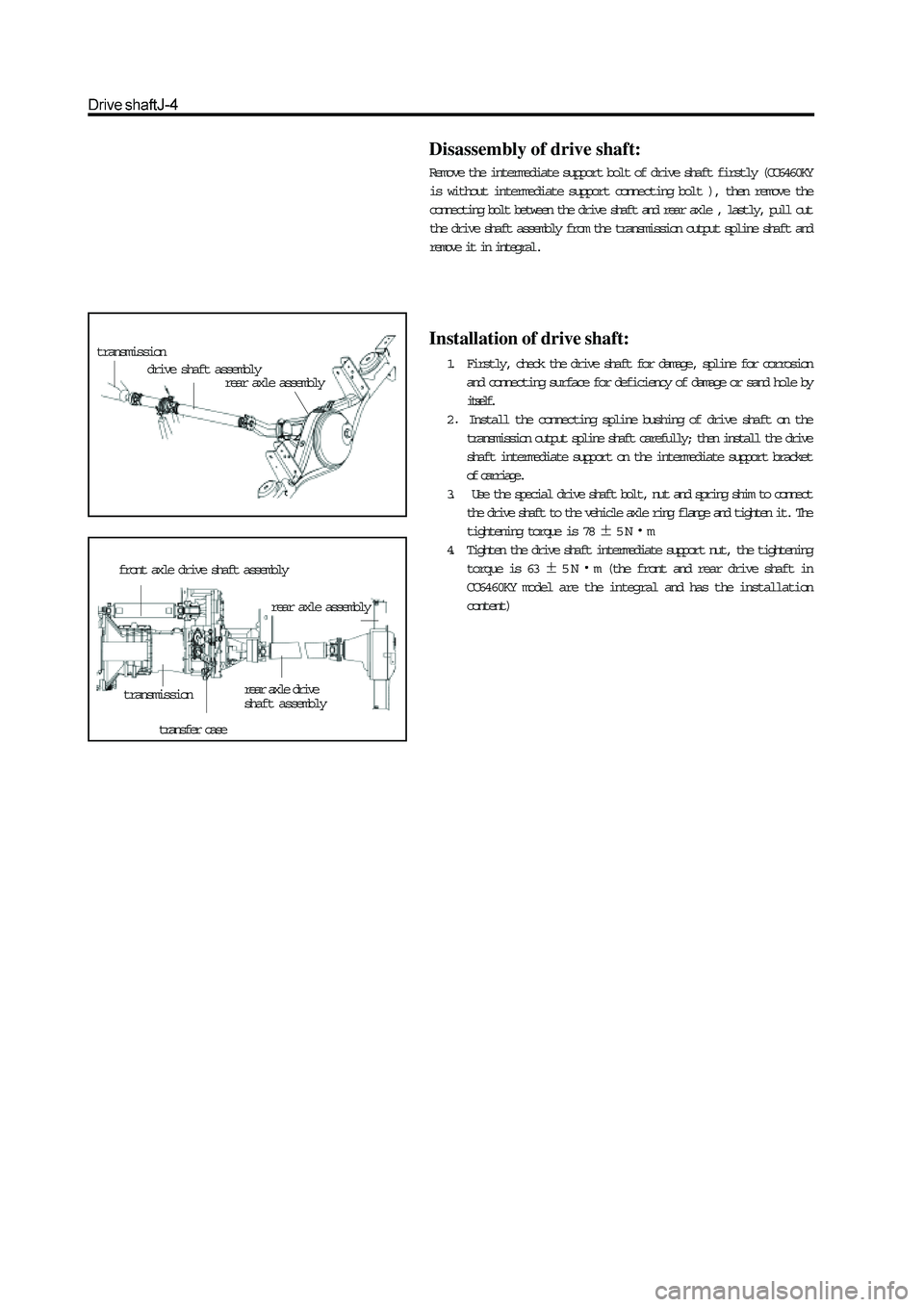
transmission
drive shaft assemblyrear axle assembly
front axle drive shaft assembly
transmissionrear axle drive
shaft assembly
transfer case
rear axle assembly
Disassembly of drive shaft:
Remove the intermediate support bolt of drive shaft firstly (CC6460KY
is without intermediate support connecting bolt ), then remove the
connecting bolt between the drive shaft and rear axle , lastly, pull out
the drive shaft assembly from the transmission output spline shaft and
remove it in integral.
Installation of drive shaft:
1. Firstly, check the drive shaft for damage, spline for corrosion
and connecting surface for deficiency of damage or sand hole by
itself.
2
Install the connecting spline bushing of drive shaft on the
transmission output spline shaft carefully; then install the drive
shaft intermediate support on the intermediate support bracket
of carriage.
3. Use the special drive shaft bolt, nut and spring shim to connect
the drive shaft to the vehicle axle ring flange and tighten it. The
tightening torque is 78
5Nm
4. Tighten the drive shaft intermediate support nut, the tightening
torque is 63
5Nm (the front and rear drive shaft in
CC6460KY model are the integral and has the installation
content)
Page 177 of 425
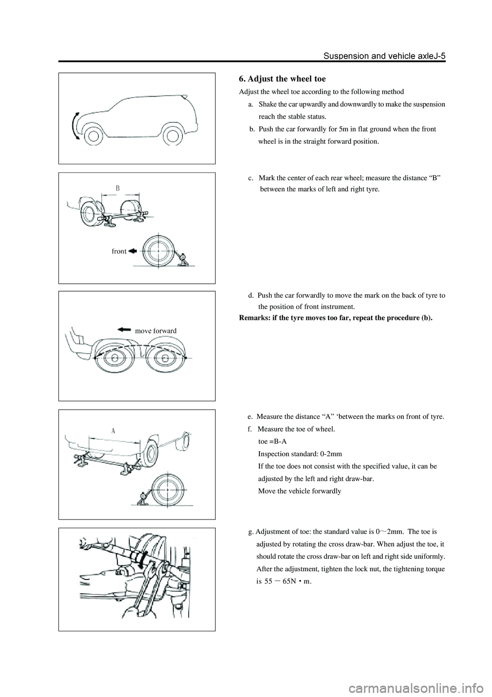
6. Adjust the wheel toe
Adjust the wheel toe according to the following method
a. Shake the car upwardly and downwardly to make the suspension
reach the stable status.
b. Push the car forwardly for 5m in flat ground when the front
wheel is in the straight forward position.
c. Mark the center of each rear wheel; measure the distance “B”
between the marks of left and right tyre.
d. Push the car forwardly to move the mark on the back of tyre to
the position of front instrument.
Remarks: if the tyre moves too far, repeat the procedure (b).
e. Measure the distance “A” ‘between the marks on front of tyre.
f. Measure the toe of wheel.
toe =B-A
Inspection standard: 0-2mm
If the toe does not consist with the specified value, it can be
adjusted by the left and right draw-bar.
Move the vehicle forwardly
g. Adjustment of toe: the standard value is 02mm. The toe is
adjusted by rotating the cross draw-bar. When adjust the toe, it
should rotate the cross draw-bar on left and right side uniformly.
After the adjustment, tighten the lock nut, the tightening torque
is 55
65Nm.