2006 GREAT WALL HOVER transmission
[x] Cancel search: transmissionPage 140 of 425

2.output shaft and gear assembly
The assembly procedure of output shaft and gear assembly (Refer to Figure 8.19),is shown as follows:
a. Check the output shaft bush for damage, replace it if necessary.
b. Check the parking detent on the ring gear for damage ; replace it if necessary.
c. Check the sealing ring groove for damage.
d. Use the automatic transmission liquid to lubricate the gasket.
e. Place the scarfing notch upwardly and install the sealing ring on the output shaft.
f. If has been removed., it should use the ring spring for reinforcement when install the ring gear on the output shaft. Ensure the
ring spring is fixed in the groove.
g. Use the Vaseline oil for lubrication; install the thrust bearing assembly NO.10 on the output shaft.
h. It should be carefully when install the output shaft on the box to avoid the damage of sealing ring.
3. Rear brake belt assembly
The assembly procedure of rear brake belt assembly (Refer to Figure 8.18) is shown as follows:
a. Check the rear brake belt for leakage or damage; check its corresponding bush and metal back .
Figure 8.18 Rear servo and brake belt
b. Install the reaction reinforcement bar on the main box, need not shim.
Caution:
Place the new brake belt in the automatic transmission liquid for about 5 minutes before install it.
c. It should be careful when install the rear brake belt on the transmission. Ensure the brake belt is installed on the correct
position.
d. Install the application support bar on the rear brake belt, then connect it to the servo motor
bar.
e. Install the cam disc and tighten the screw according to the instruction.
Page 141 of 425

Figure 8.19 Position of thrust bearing and sealing pad
4. Rear servo assembly
Install the rear servo assembly (Refer to Figure 8.18), the procedure is shown as follows:
a. Check the servo piston O-ring and washer for damage.
b. Use the transmission fluid to lubricate the servo piston O-ring and install the O-ring on the piston groove.
c. Install the piston on the housing; ensure the O-ring is compressed to position, but do not excess.
d. Adjust the spring and piston sleeve; then install the rear servo brake bar on the sleeve.
Caution:
Do not coat the washer with the Vaseline.
e. Install the housing installed with washer on the case.
f. Provide the bolt with the Loctite567 sealant and install it; ensure the bolt is tightened according to the specification.
5. Planet carrier assembly and central support
The installation process of planet carrier assembly and central support is shown as follows:
a. Check the bracket and planet assembly for damage or abnormal and ensure all pinion rotates freely and the pinion axle end
floats in the allowable range; described as 9.2.
b. Install the one-way clutch fixing plate on the planet carrier and ensure the internal edge points to the downwardly. Check the
one-way clutch and brake accessory for damage; replace it according to the requirement.
c. Install the external race on the drum. Press sown the ring race to bottom of drum and install the fixing ring spring. Ensure the
ring spring is installed in the groove stably. Refer to Figure 8.20.
d. Install the one-way brake on the external race with the lip upwardly. Use the automatic transmission liquid to lubricate the
brake accessories. Refer to Figure 8.20.
Page 142 of 425

connecting housing (4WD)connecting housing
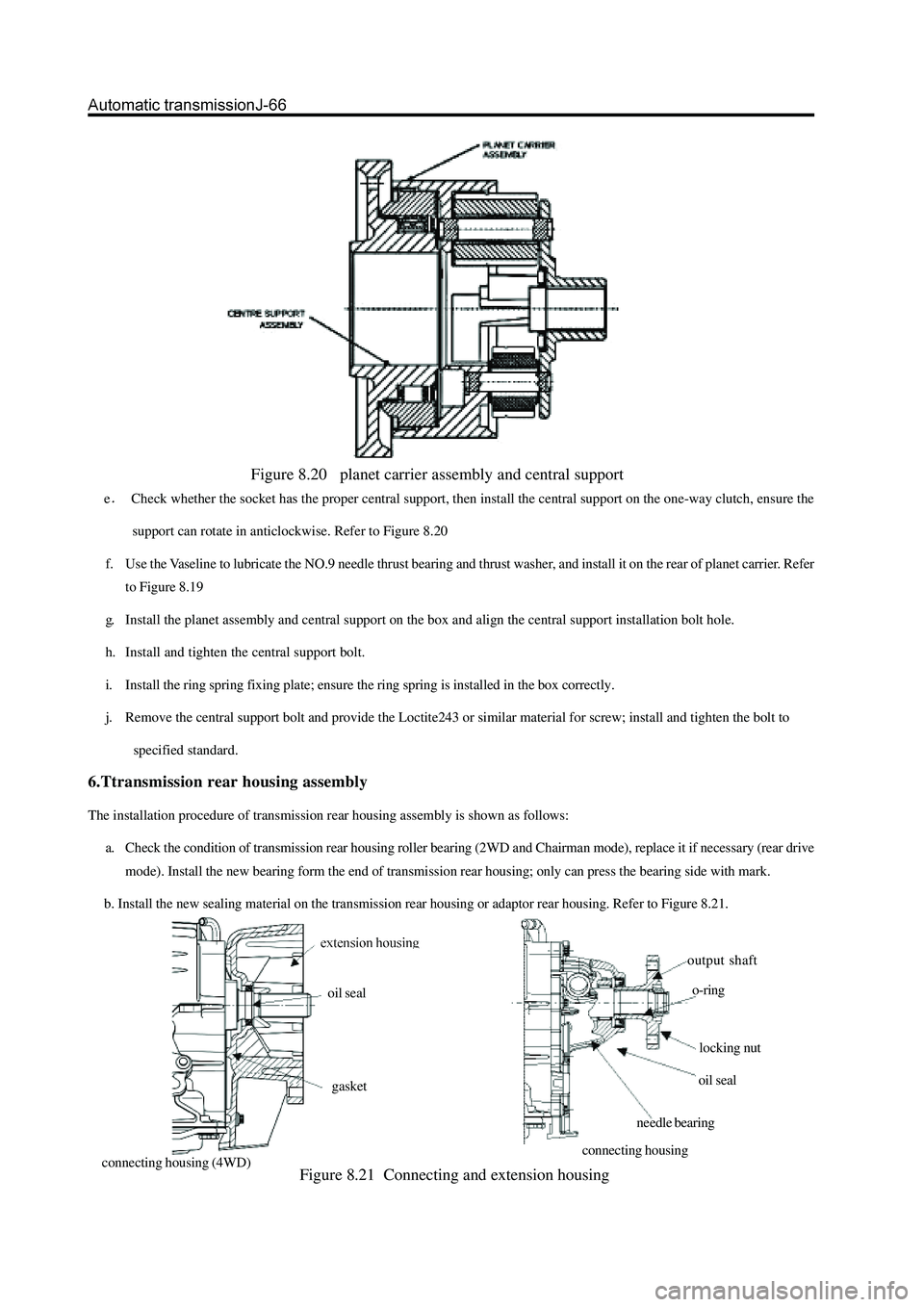
Figure 8.20 planet carrier assembly and central support
eCheck whether the socket has the proper central support, then install the central support on the one-way clutch, ensure the
support can rotate in anticlockwise. Refer to Figure 8.20
f. Use the Vaseline to lubricate the NO.9 needle thrust bearing and thrust washer, and install it on the rear of planet carrier. Refer
to Figure 8.19
g. Install the planet assembly and central support on the box and align the central support installation bolt hole.
h. Install and tighten the central support bolt.
i. Install the ring spring fixing plate; ensure the ring spring is installed in the box correctly.
j. Remove the central support bolt and provide the Loctite243 or similar material for screw; install and tighten the bolt to
specified standard.
6.Ttransmission rear housing assembly
The installation procedure of transmission rear housing assembly is shown as follows:
a. Check the condition of transmission rear housing roller bearing (2WD and Chairman mode), replace it if necessary (rear drive
mode). Install the new bearing form the end of transmission rear housing; only can press the bearing side with mark.
b. Install the new sealing material on the transmission rear housing or adaptor rear housing. Refer to Figure 8.21.
Figure 8.21 Connecting and extension housing
output shaft
o-ring
locking nut
oil seal
needle bearing oil seal
gasket
Page 143 of 425

Caution:
Do not use the Vaseline to fix the washer.
c. Install the transmission rear housing or adaptor rear housing with the new washer.
Caution:
Refer to the description in section 8.3.17 related installation of output flange assembly (rear wheel drive).
d. Install the transmission rear housing (rear wheel drive) or adaptor rear housing (4WD ) and tighten the bolt.
e. Provide the Loctite202 or equivalent sealant to the rear housing or connector and process the installation. Ensure the bolt is
tightened according to the specification. (Refer to Figure 8.1)
7. Front servo assembly
Caution:
Ensure the front servo clamp ring is installed correctly; ensure the ring spring and spark gap points to the bottom. Refer
to Figure 8.22.
The assembly procedure of front servo assembly (Refer to Figure 8.22) is shown as follows:
a. Use the automatic transmission liquid to lubricate the housing O-ring and install it on the housing.
b. Use the automatic transmission liquid to lubricate the housing O-ring and install it on the piston.
c. Install the piston, brake lever, spring, washer, base and fixing ring.
d. Install the piston brake lever assembly on the front servo housing.
e. Install the front servo plug and spring in the box.
f. Install the front servo assembly in the box.
g. Press down the servo housing and install the fixing ring spring of servo housing. Align the spark gap and coil track and ensure
it is installed in the groove properly. Figure 8.22 front servo and brake belt
8. Brake belt assembly
The assembly process of brake belt assembly is shown as follows:
a. Install the reaction reinforcement lever on the housing.
b. Check the brake belt for crack or damage; check the bush and metal back.
c. Install the support retainer on the brake belt (Refer to Figure 8.23).Note that the later transmission modes will not adopt the
support retainer.
Caution:
Place the new brake belt in the automatic transmission liquid for about 5 minutes before install it.
Page 144 of 425

Figure 8.23 Installation of brake belt press lever
d. Install the brake belt on the transmission, ensure it is installed on the correct position.
e. Install the reaction support on the fixing plate and connect it to the brake belt and reinforcement lever. Install the application
support on thea fixing plate and connect it to the brake belt and servo piston bar.
9.C2/clutch C4 assembly
Caution:
Check the piston for crack, especially for piston C2.
Must not mix the clutch piston out and back spring.
Ensure the correct installation of clip ring
The assembly procedure of C2/clutch C4 assembly (refer to 8.24) is shown as follows:
a. Ensure the cleanness of internal oil inlet of cylinder; check the discharge outlet of piston C2 for cleanness; use the transmission
liquid to lubricate the O-ring.
Caution:
The O-ring must not be winded in groove.
Figure 8.24 Typical C2/C4clutch assembly
b. Install the small O-ring in the inner groove; install the large O-ring in the external groove of piston; check the discharge outlet
of C4 piston for cleanness.
c. Use the transmission liquid to lubricate the O-ring; install the small O-ring in the inner groove; install the large O-ring in the
external groove of piston.
d. Make the C2/clutch C4 hole face upwardly; install the clutch cylinder; place the C4 piston in the original position proper for
C2 piston during the calibration..
e. Install the C2/C4 piston assembly on the cylinder; ensure the external hole of cylinder align with the discharge outlet of piston,
until the external diameter of C2 piston enters into the internal diameter of cylinder.
Page 145 of 425

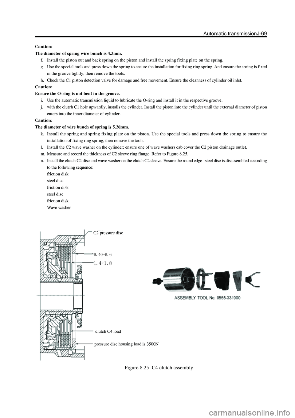
Figure 8.25 C4 clutch assembly
Caution:
The diameter of spring wire bunch is 4.3mm.
f. Install the piston out and back spring on the piston and install the spring fixing plate on the spring.
g. Use the special tools and press down the spring to ensure the installation for fixing ring spring. And ensure the spring is fixed
in the groove tightly, then remove the tools.
h. Check the C1 piston detection valve for damage and free movement. Ensure the cleanness of cylinder oil inlet.
Caution:
Ensure the O-ring is not bent in the groove.
i. Use the automatic transmission liquid to lubricate the O-ring and install it in the respective groove.
j. with the clutch C1 hole upwardly, installs the cylinder. Install the piston into the cylinder until the external diameter of piston
enters into the inner diameter of cylinder.
Caution:
The diameter of wire bunch of spring is 5.26mm.
k. Install the spring and spring fixing plate on the piston. Use the special tools and press down the spring to ensure the
installation of fixing ring spring, then remove the tools.
l. Install the C2 wave washer on the cylinder; ensure one of wave washers cab cover the C2 piston drainage outlet.
m. Measure and record the thickness of C2 sleeve ring flange. Refer to Figure 8.25.
n. Install the clutch C4 disc and wave washer on the clutch C2 sleeve. Ensure the round edge steel disc is disassembled according
to the following sequence:
friction disk
steel disc
friction disk
steel disc
friction disk
Wave washer
C2 pressure disc
pressure disc housing load is 3500N
clutch C4 load
Page 146 of 425

o. Maintain the horizontal position of cylinder , install the sleeve and clutch disk assembly on the cylinder; ensure the top of
washer and external hole of cylinder are in order until the sleeve can contact the C2 wave plate.
Caution:
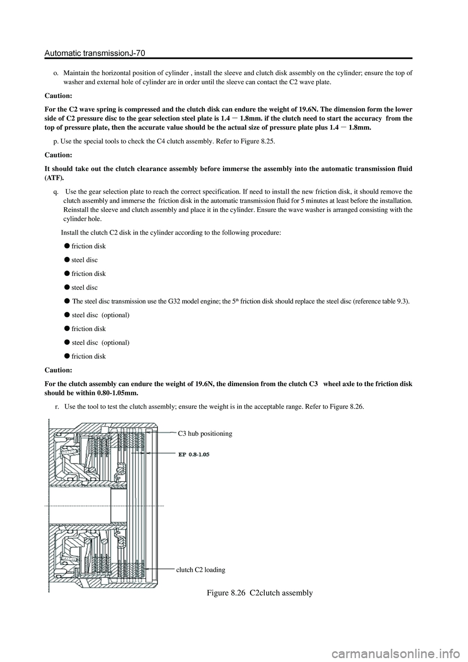
For the C2 wave spring is compressed and the clutch disk can endure the weight of 19.6N. The dimension form the lower
side of C2 pressure disc to the gear selection steel plate is 1.4
1.8mm. if the clutch need to start the accuracy from the
top of pressure plate, then the accurate value should be the actual size of pressure plate plus 1.4
1.8mm.
p. Use the special tools to check the C4 clutch assembly. Refer to Figure 8.25.
Caution:
It should take out the clutch clearance assembly before immerse the assembly into the automatic transmission fluid
(ATF).
q. Use the gear selection plate to reach the correct specification. If need to install the new friction disk, it should remove the
clutch assembly and immerse the friction disk in the automatic transmission fluid for 5 minutes at least before the installation.
Reinstall the sleeve and clutch assembly and place it in the cylinder. Ensure the wave washer is arranged consisting with the
cylinder hole.
Install the clutch C2 disk in the cylinder according to the following procedure:
friction disk
steel disc
friction disk
steel disc
The steel disc transmission use the G32 model engine; the 5th friction disk should replace the steel disc (reference table 9.3).
steel disc (optional)
friction disk
steel disc (optional)
friction disk
Caution:
For the clutch assembly can endure the weight of 19.6N, the dimension from the clutch C3 wheel axle to the friction disk
should be within 0.80-1.05mm.
r. Use the tool to test the clutch assembly; ensure the weight is in the acceptable range. Refer to Figure 8.26.
C3 hub positioning
clutch C2 loading
Figure 8.26 C2clutch assembly
Page 147 of 425

v. Install the thrust disc on the cylinder internal wheel axle. Refer to Figure 8.24and 8.19.
w. Connect the C2 /clutch C4 wheel axle assembly in clutch C4 disc, install the clutch C2 disc. Install the C3 wheel axle and
reinforce it by ring spring; ensure the ring spring is installed in the groove fixedly. Please refer to Figure 8.24.
10. Clutch C3 and reverse central gear system
The assembly procedure of clutch C3 and reverse central gear assembly (refer to Figure 8.28) is shown as follows:
Check the cleanness of hole on cylinder. Caution:
It should take out the clutch clearance assembly before immerse the assembly into the automatic transmission fluid
(ATF).
s. Use the gear selection plate to reach the correct specification. It should remove the clutch assembly and immerse the friction
disk in the automatic transmission fluid for 5 minutes at least before the installation if install the new friction disks. Lubricate
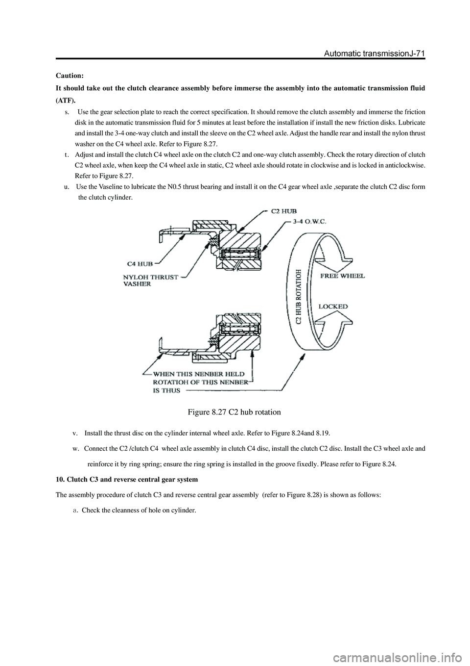
and install the 3-4 one-way clutch and install the sleeve on the C2 wheel axle. Adjust the handle rear and install the nylon thrust
washer on the C4 wheel axle. Refer to Figure 8.27.
t . Adjust and install the clutch C4 wheel axle on the clutch C2 and one-way clutch assembly. Check the rotary direction of clutch
C2 wheel axle, when keep the C4 wheel axle in static, C2 wheel axle should rotate in clockwise and is locked in anticlockwise.
Refer to Figure 8.27.
u. Use the Vaseline to lubricate the N0.5 thrust bearing and install it on the C4 gear wheel axle ,separate the clutch C2 disc form
the clutch cylinder.
Figure 8.27 C2 hub rotation