2006 GREAT WALL HOVER transmission
[x] Cancel search: transmissionPage 161 of 425

Figure 8.58 Tighten sequence of bolt form valve to box
15. Installation of oil filter and oil bottom shell
Caution:
a. It should replace the filter when a important mechanical component is damaged and assemble a transmission.
b. To assist the assembly of sealing gasket groove, please coat the surface of oil pan and washer with thin Vaseline to
ensure the sealing gasket is in the groove. Do not rotate the washer, otherwise it will cause the distort or incline of
groove.
Page 162 of 425

Figure 8.59 Bushing of engine oil filter
Figure 8.60 Installation of engine oil filter
Figure 8.61 Tightening sequence of oil pan bolt
It should abide by follows when assemble the oil filter and oil sump tank (Refer to Figure 8.59and Figure 8.60):
a. Use the automatic transmission liquid to lubricate the spring ring of gasket of lubrication oil.
b. Install the oil filter on the valve carefully. During the installation, the socket must be inclined. Refer to Figure 8.59.
c. Fix the oil cleaner assembly.
d. Check whether the magnet is installed in the recess on the corner of oil bottom shell.
e. Assemble the groove on the oil bottom shell. The groove must be bent during the installation.
Page 163 of 425

f. Make the installation of oil bottom shell is proper for transfer case and the tighten the safety valve according to the
specification and sequence (Refer to Figure 8.61). do not distort it.
16.Torque converter and support sleeve assembly
Install the hydraulic torque converter and housing assembly, the procedure is shown as follows:
a. Install the hydraulic torque converter housing on the main case.
Caution:
All hardware should be installed correctly and comply with the specification.
b. Use the Loctite243 or equivalent to fix the torque converter housing; install and tighten it to standard specification.
c. Install the torque converter; ensure the pump gear sealing is installed correctly.
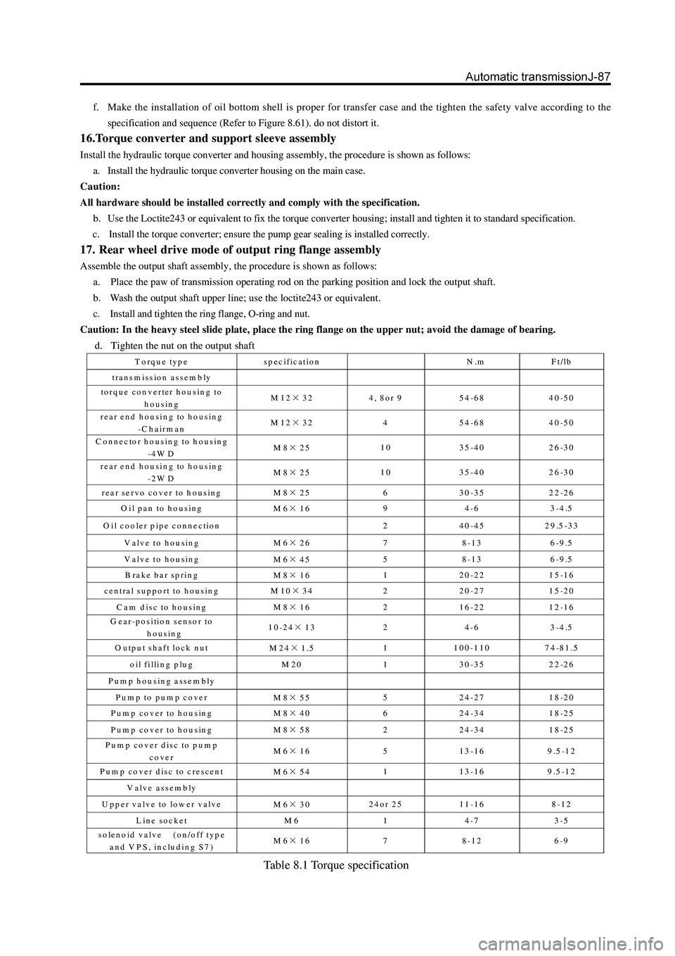
17. Rear wheel drive mode of output ring flange assembly
Assemble the output shaft assembly, the procedure is shown as follows:
a. Place the paw of transmission operating rod on the parking position and lock the output shaft.
b. Wash the output shaft upper line; use the loctite243 or equivalent.
c. Install and tighten the ring flange, O-ring and nut.
Caution: In the heavy steel slide plate, place the ring flange on the upper nut; avoid the damage of bearing.
d. Tighten the nut on the output shaft
Torque type specification N.m Ft/lb
tra n s m iss io n as se m b ly
torque converter housing to
housing M12×32 4, 8or 9 54-68 40-50
rear end housing to housing
-C h a irm a n M12×32 4 54-68 40-50
C onnector housing to housing
-4 W D M8×25 10 35-40 26-30
rear end housing to housing
-2 W D M8×25 10 35-40 26-30
rear servo cover to housing
M8×25 6 30-35 22-26
O il pan to housing
M6×16 9 4-6 3-4.5
O il cooler pipe connection
2 40-45 29.5-33
V alve to housing
M6×26 7 8-13 6-9.5
V alve to housing
M6×45 5 8-13 6-9.5
B rake bar spring
M8×16 1 20-22 15-16
central support to housing
M10×34 2 20-27 15-20
C am disc to housing
M8×16 2 16-22 12-16
G ear-position sensor to
housing 10-24×13 2 4-6 3-4.5
O utput shaft lock nut
M24×1.5 1 100-110 74-81.5
oil filling plug M 20 1 30-35 22-26
Pump housing assembly
Pump to pump cover
M8×55 5 24-27 18-20
Pum p cover to housing
M8×40 6 24-34 18-25
Pum p cover to housing
M8×58 2 24-34 18-25
Pum p cover disc to pum p
cover M6×16 5 13-16 9.5-12
Pum p cover disc to crescent
M6×54 1 13-16 9.5-12
Valve assem bly
U p p e r v a lv e to lo w e r v a lv e
M6×30 24or 25 11-16 8-12
Line socket M 6 1 4-7 3-5
solenoid valve (on/off type
and VPS, including S7) M6×16 7 8-12 6-9
Table 8.1 Torque specification
Page 164 of 425

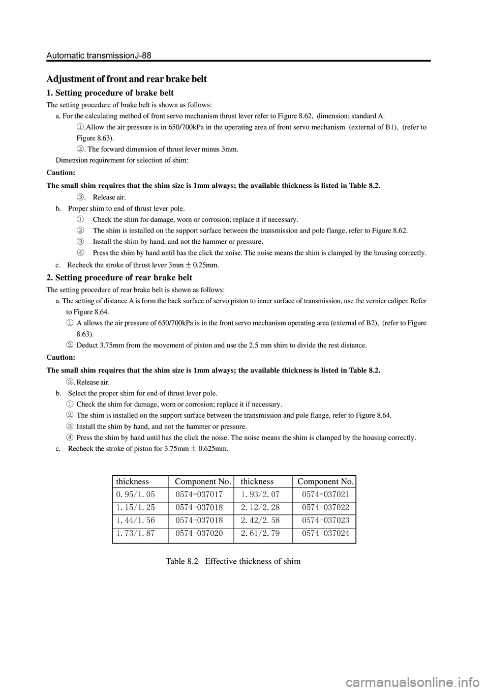
thickness Component No. thickness Component No.
Adjustment of front and rear brake belt
1. Setting procedure of brake belt
The setting procedure of brake belt is shown as follows:
a. For the calculating method of front servo mechanism thrust lever refer to Figure 8.62, dimension; standard A.
.Allow the air pressure is in 650/700kPa in the operating area of front servo mechanism (external of B1), (refer to
Figure 8.63).
. The forward dimension of thrust lever minus 3mm.
Dimension requirement for selection of shim:
Caution:
The small shim requires that the shim size is 1mm always; the available thickness is listed in Table 8.2.
. Release air.
b. Proper shim to end of thrust lever pole.
Check the shim for damage, worn or corrosion; replace it if necessary.
The shim is installed on the support surface between the transmission and pole flange, refer to Figure 8.62.
Install the shim by hand, and not the hammer or pressure.
Press the shim by hand until has the click the noise. The noise means the shim is clamped by the housing correctly.
c. Recheck the stroke of thrust lever 3mm
0.25mm.
2. Setting procedure of rear brake belt
The setting procedure of rear brake belt is shown as follows:
a. The setting of distance A is form the back surface of servo piston to inner surface of transmission, use the vernier caliper. Refer
to Figure 8.64.
A allows the air pressure of 650/700kPa is in the front servo mechanism operating area (external of B2), (refer to Figure
8.63).
Deduct 3.75mm from the movement of piston and use the 2.5 mm shim to divide the rest distance.
Caution:
The small shim requires that the shim size is 1mm always; the available thickness is listed in Table 8.2.
. Release air.
b. Select the proper shim for end of thrust lever pole.
Check the shim for damage, worn or corrosion; replace it if necessary.
The shim is installed on the support surface between the transmission and pole flange, refer to Figure 8.64.
Install the shim by hand, and not the hammer or pressure.
Press the shim by hand until has the click the noise. The noise means the shim is clamped by the housing correctly.
c. Recheck the stroke of piston for 3.75mm
0.625mm.
Table 8.2 Effective thickness of shim
Page 167 of 425

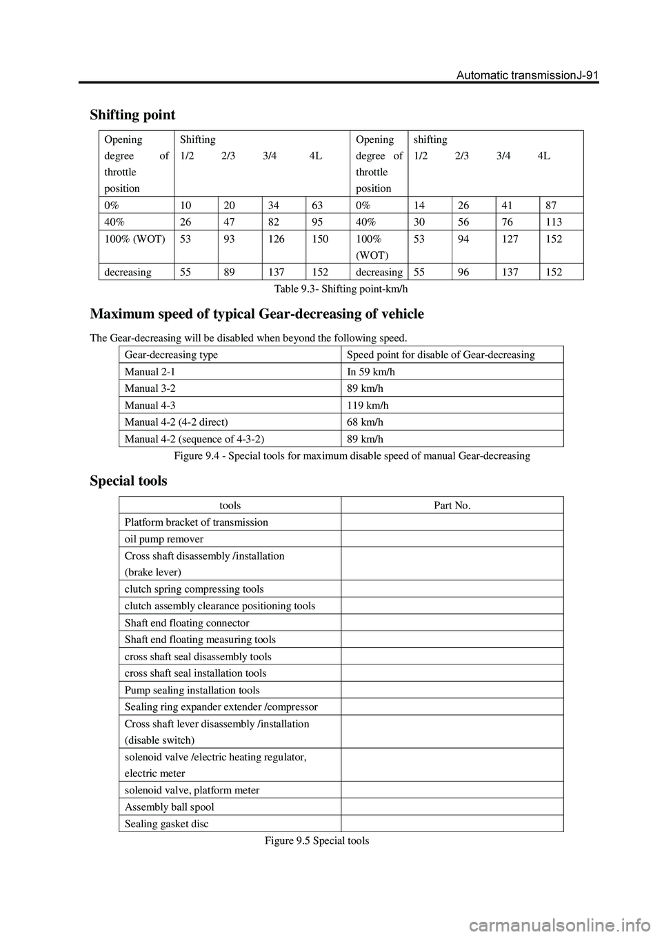
Shifting point
Opening
degree of
throttle
position Shifting
1/2 2/3 3/4 4L Opening
degree of
throttle
position shifting
1/2 2/3 3/4 4L
0% 10 20 34 63 0% 14 26 41 87
40% 26 47 82 95 40% 30 56 76 113
100% (WOT) 53 93 126 150 100%
(WOT) 53
94 127 152
decreasing 55 89 137 152 decreasing 55 96 137 152
Table 9.3- Shifting point-km/h
Maximum speed of typical Gear-decreasing of vehicle
The Gear-decreasing will be disabled when beyond the following speed.
Gear-decreasing type Speed point for disable of Gear-decreasing
Manual 2-1 In 59 km/h
Manual 3-2 89 km/h
Manual 4-3 119 km/h
Manual 4-2 (4-2 direct) 68 km/h
Manual 4-2 (sequence of 4-3-2) 89 km/h
Figure 9.4 - Special tools for maximum disable speed of manual Gear-decreasing
Special tools
tools Part No.
Platform bracket of transmission
oil pump remover
Cross shaft disassembly /installation
(brake lever)
clutch spring compressing tools
clutch assembly clearance positioning tools
Shaft end floating connector
Shaft end floating measuring tools
cross shaft seal disassembly tools
cross shaft seal installation tools
Pump sealing installation tools
Sealing ring expander extender /compressor
Cross shaft lever disassembly /installation
(disable switch)
solenoid valve /electric heating regulator,
electric meter
solenoid valve, platform meter
Assembly ball spool
Sealing gasket disc
Figure 9.5 Special tools
Page 170 of 425

Cautions
Do not clamp the drive shaft bushing too tightened by the bench
vice to avoid the deformation.
failure Possible causes Method
Noise The spline of universal-joint fork is worn
The intermediate bearing is worn
The cross-axle bearing is worn or jammed Replace the universal-joint
fork
Replace the intermediate
bearing
Replace the cross-axle bearing
vibration Runout of drive shaft
Unbalance of drive shaft
The rear bearing bushing of transmission
extended housing is worn
The spline of universal-joint fork is jammed Replace the drive shaft
Replace the drive shaft
Replace the bushing
Replace the universal-joint
fork
Page 172 of 425

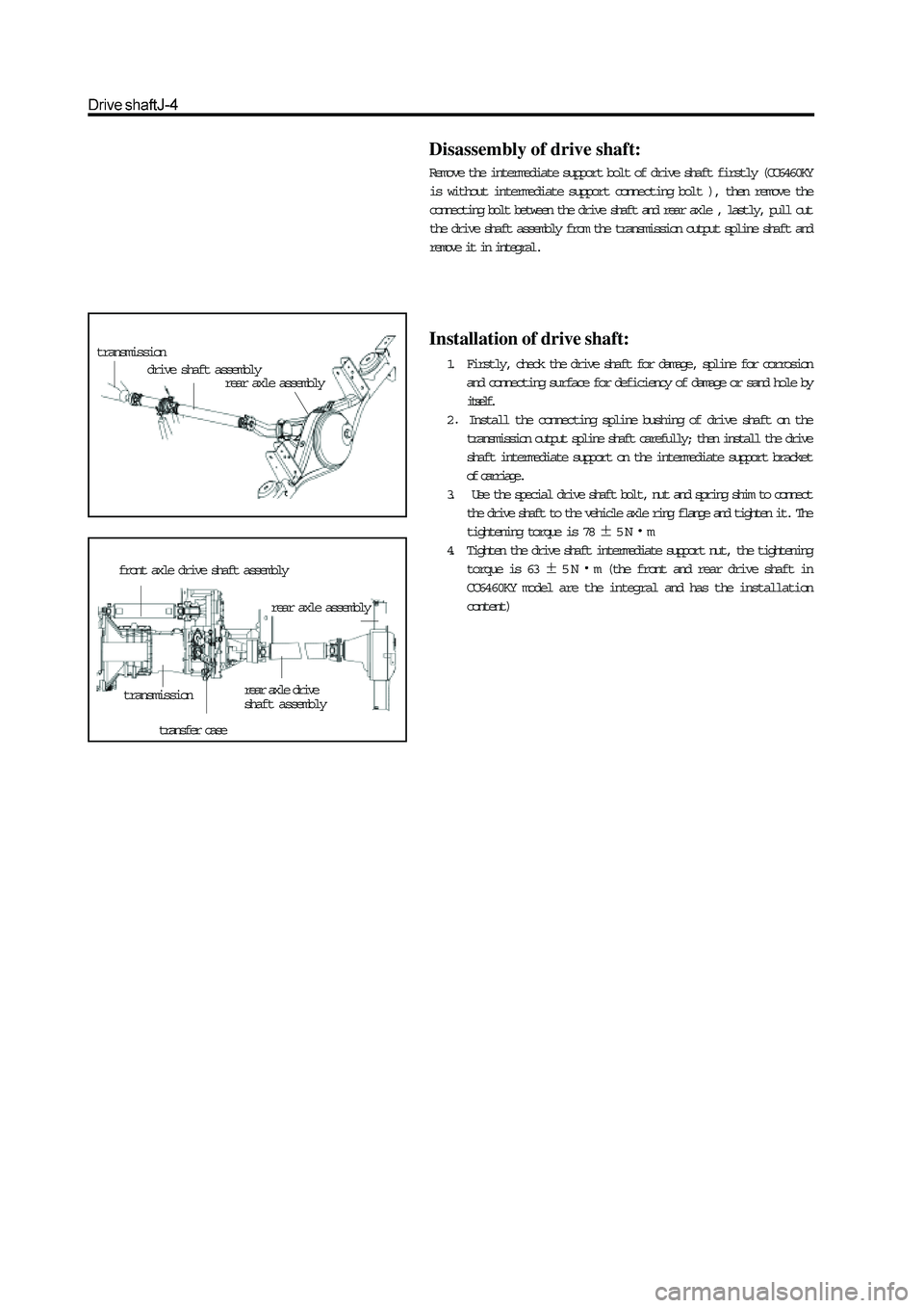
transmission
drive shaft assemblyrear axle assembly
front axle drive shaft assembly
transmissionrear axle drive
shaft assembly
transfer case
rear axle assembly
Disassembly of drive shaft:
Remove the intermediate support bolt of drive shaft firstly (CC6460KY
is without intermediate support connecting bolt ), then remove the
connecting bolt between the drive shaft and rear axle , lastly, pull out
the drive shaft assembly from the transmission output spline shaft and
remove it in integral.
Installation of drive shaft:
1. Firstly, check the drive shaft for damage, spline for corrosion
and connecting surface for deficiency of damage or sand hole by
itself.
2
Install the connecting spline bushing of drive shaft on the
transmission output spline shaft carefully; then install the drive
shaft intermediate support on the intermediate support bracket
of carriage.
3. Use the special drive shaft bolt, nut and spring shim to connect
the drive shaft to the vehicle axle ring flange and tighten it. The
tightening torque is 78
5Nm
4. Tighten the drive shaft intermediate support nut, the tightening
torque is 63
5Nm (the front and rear drive shaft in
CC6460KY model are the integral and has the installation
content)
Page 377 of 425

Safety airbag-7
Description of flash code
The failure code transmission is completed by SRS-ECU’s input to the defined diagnostic scanner through the maintenance system’s
serial data interface. (X-431 diagnostic scanner) Failure code of diagnosis
Failure Failure code Flash code
1 No storage error $12
2 Front airbag driver’s, high resistance $9,021 $21
3 Front airbag driver’s , low resistance $9,022 $22
4 Front airbag driver ’s, short-circuit of GND $9,024 $24
5 front airbag driver ’s , short –circuit of VBATT $9,025 $25
6 front airbag passenger, high resistance $9,015 $15
7 front airbag passenger, low resistance $9,016 $16
8 front airbag passenger , short-circuit of GND $9,018 $18
9 Front airbag passenger , short-circuit of VBTT $9,019 $19
10 High voltage of battery $9,031 $31
11 Low voltage of battery $9,032 $32
12 Failure of alarm lamp $9,061 $61
13 Internal failure (replace SDM) $9,071 $71
14 Front collision record $9,051 $51
15 Side collision driver’s record $9,056 $56
16 Side collision passenger record $9,057 $57
17 Retightened safety belt collision $9,058 $58
18 Beyond the allowable repeat usage times $9,054 $54
3. Interior failure
The micro controller can test the following items not only in starting detection but also in cyclic diagnosis detection.
a. Ignition circuit triggers the transistor: The high-side transistor is detected not only in the starting detection but also in the
circulation diagnosis. But for the low-side transistor is opened when is connected to power supply directly, so the low-side
transistor only can be detected in the starting detection to avoid the misexplosion.
b. The ignition voltage is provided by the booster transformer.
c. The acceleration sensor is detected by itself when start the detection.
d. Allowable deviation scope of acceleration sensor in circulation diagnosis.
e. Micro controller includes (AD converter, ROM, RAM etc.)
f. Status of safety sensor
Cautions:
Connector of explosion tube circuit has the short-circuit bar. When the connector is not connected, the end (+) of
explosion tube is connected to end (-) directly to prevent the failure outspread caused by static. When the connector
is bas and short-circuit bar is connected, the failure may not be eliminated.
An external watch dog can detect the operating status of micro controller. It can trigger the watchdog when the micro con
troller has failure. The watch dog will reset the micro-controller and light the alarm lamp.