Page 1006 of 5267
P0137-O2 SENSOR 1/2 CIRCUIT LOW
For a complete wiring diagramRefer to Section 8W.
Page 1007 of 5267

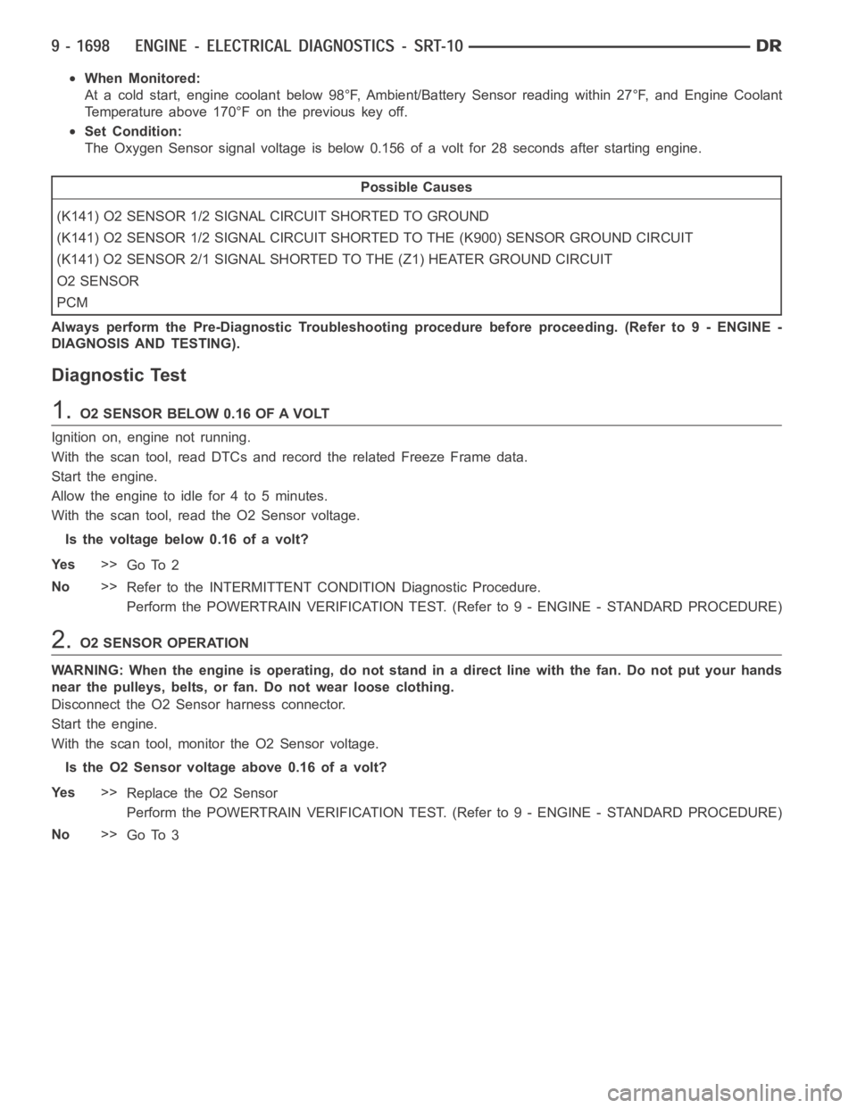
When Monitored:
At a cold start, engine coolant below 98°F, Ambient/Battery Sensor readingwithin27°F,andEngineCoolant
Temperature above 170°F on the previous key off.
Set Condition:
The Oxygen Sensor signal voltage is below 0.156 of a volt for 28 seconds after starting engine.
Possible Causes
(K141) O2 SENSOR 1/2 SIGNAL CIRCUIT SHORTED TO GROUND
(K141) O2 SENSOR 1/2 SIGNAL CIRCUIT SHORTED TO THE (K900) SENSOR GROUND CIRCUIT
(K141) O2 SENSOR 2/1 SIGNAL SHORTED TO THE (Z1) HEATER GROUND CIRCUIT
O2 SENSOR
PCM
Always perform the Pre-Diagnostic Troubleshooting procedure before proceeding. (Refer to 9 - ENGINE -
DIAGNOSIS AND TESTING).
Diagnostic Test
1.O2 SENSOR BELOW 0.16 OF A VOLT
Ignition on, engine not running.
With the scan tool, read DTCs and record the related Freeze Frame data.
Start the engine.
Allow the engine to idle for 4 to 5 minutes.
With the scan tool, read the O2 Sensor voltage.
Is the voltage below 0.16 of a volt?
Ye s>>
Go To 2
No>>
Refer to the INTERMITTENT CONDITION Diagnostic Procedure.
Perform the POWERTRAIN VERIFICATION TEST. (Refer to 9 - ENGINE - STANDARD PROCEDURE)
2.O2 SENSOR OPERATION
WARNING: When the engine is operating, do not stand in a direct line with thefan. Do not put your hands
near the pulleys, belts, or fan. Do not wear loose clothing.
Disconnect the O2 Sensor harness connector.
Start the engine.
With the scan tool, monitor the O2 Sensor voltage.
IstheO2Sensorvoltageabove0.16ofavolt?
Ye s>>
Replace the O2 Sensor
Perform the POWERTRAIN VERIFICATION TEST. (Refer to 9 - ENGINE - STANDARD PROCEDURE)
No>>
Go To 3
Page 1008 of 5267

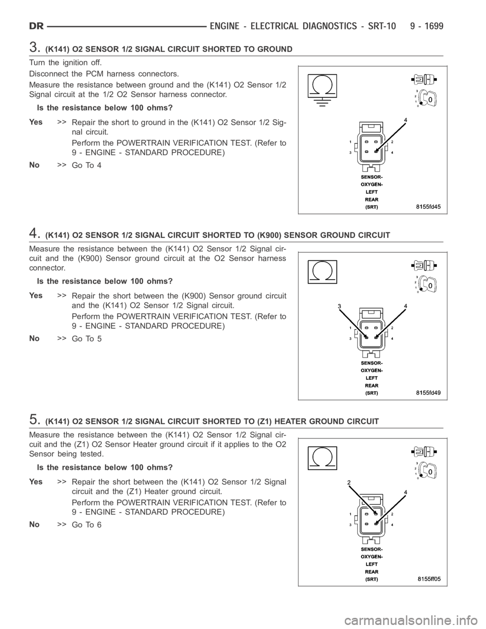
3.(K141) O2 SENSOR 1/2 SIGNAL CIRCUIT SHORTED TO GROUND
Turn the ignition off.
Disconnect the PCM harness connectors.
Measure the resistance between ground and the (K141) O2 Sensor 1/2
Signal circuit at the 1/2 O2 Sensor harness connector.
Istheresistancebelow100ohms?
Ye s>>
Repair the short to ground in the (K141) O2 Sensor 1/2 Sig-
nal circuit.
Perform the POWERTRAIN VERIFICATION TEST. (Refer to
9 - ENGINE - STANDARD PROCEDURE)
No>>
Go To 4
4.(K141) O2 SENSOR 1/2 SIGNAL CIRCUIT SHORTED TO (K900) SENSOR GROUND CIRCUIT
Measure the resistance between the (K141) O2 Sensor 1/2 Signal cir-
cuit and the (K900) Sensor ground circuit at the O2 Sensor harness
connector.
Istheresistancebelow100ohms?
Ye s>>
Repair the short between the (K900) Sensor ground circuit
and the (K141) O2 Sensor 1/2 Signal circuit.
Perform the POWERTRAIN VERIFICATION TEST. (Refer to
9 - ENGINE - STANDARD PROCEDURE)
No>>
Go To 5
5.(K141) O2 SENSOR 1/2 SIGNAL CIRCUIT SHORTED TO (Z1) HEATER GROUND CIRCUIT
Measure the resistance between the (K141) O2 Sensor 1/2 Signal cir-
cuit and the (Z1) O2 Sensor Heater ground circuit if it applies to the O2
Sensor being tested.
Istheresistancebelow100ohms?
Ye s>>
Repair the short between the (K141) O2 Sensor 1/2 Signal
circuit and the (Z1) Heater ground circuit.
Perform the POWERTRAIN VERIFICATION TEST. (Refer to
9 - ENGINE - STANDARD PROCEDURE)
No>>
Go To 6
Page 1010 of 5267
P0138-O2 SENSOR 1/2 CIRCUIT HIGH
For a complete wiring diagramRefer to Section 8W.
Page 1011 of 5267

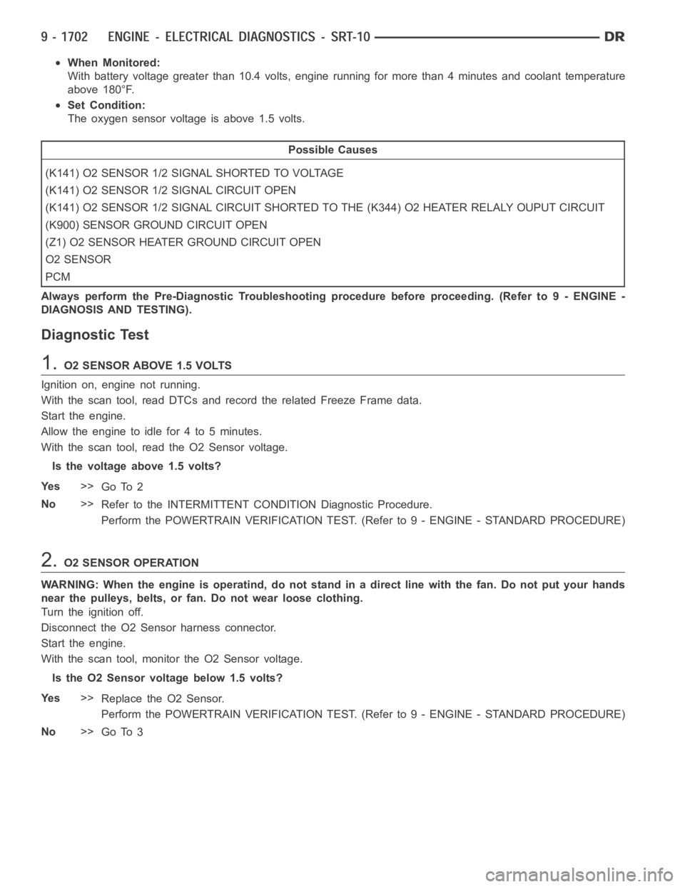
When Monitored:
With battery voltage greater than 10.4 volts, engine running for more than4 minutes and coolant temperature
above 180°F.
Set Condition:
The oxygen sensor voltage is above 1.5 volts.
Possible Causes
(K141) O2 SENSOR 1/2 SIGNAL SHORTED TO VOLTAGE
(K141) O2 SENSOR 1/2 SIGNAL CIRCUIT OPEN
(K141) O2 SENSOR 1/2 SIGNAL CIRCUIT SHORTED TO THE (K344) O2 HEATER RELALY OUPUT CIRCUIT
(K900) SENSOR GROUND CIRCUIT OPEN
(Z1) O2 SENSOR HEATER GROUND CIRCUIT OPEN
O2 SENSOR
PCM
Always perform the Pre-Diagnostic Troubleshooting procedure before proceeding. (Refer to 9 - ENGINE -
DIAGNOSIS AND TESTING).
Diagnostic Test
1.O2 SENSOR ABOVE 1.5 VOLTS
Ignition on, engine not running.
With the scan tool, read DTCs and record the related Freeze Frame data.
Start the engine.
Allow the engine to idle for 4 to 5 minutes.
With the scan tool, read the O2 Sensor voltage.
Is the voltage above 1.5 volts?
Ye s>>
Go To 2
No>>
Refer to the INTERMITTENT CONDITION Diagnostic Procedure.
Perform the POWERTRAIN VERIFICATION TEST. (Refer to 9 - ENGINE - STANDARD PROCEDURE)
2.O2 SENSOR OPERATION
WARNING: When the engine is operatind, do not stand in a direct line with thefan. Do not put your hands
near the pulleys, belts, or fan. Do not wear loose clothing.
Turn the ignition off.
Disconnect the O2 Sensor harness connector.
Start the engine.
With the scan tool, monitor the O2 Sensor voltage.
Is the O2 Sensor voltage below 1.5 volts?
Ye s>>
Replace the O2 Sensor.
Perform the POWERTRAIN VERIFICATION TEST. (Refer to 9 - ENGINE - STANDARD PROCEDURE)
No>>
Go To 3
Page 1012 of 5267
3.(K141) O2 SENSOR 1/2 SIGNAL CIRCUIT SHORTED TO VOLTAGE
Turn the ignition off.
Disconnect the PCM harness connectors.
Ignition on, engine not running.
Using a 12-volt test light connected to ground, probe the (K141) O2
Sensor 1/2 Signal circuit at the 1/2 O2 Sensor harness connector.
Does the test light illuminate brightly?
Ye s>>
Repair the short to voltage in the (K141) O2 Sensor 1/2
Signal circuit.
Perform the POWERTRAIN VERIFICATION TEST. (Refer to
9 - ENGINE - STANDARD PROCEDURE)
No>>
Go To 4
4.(K141) O2 SENSOR 1/2 SIGNAL CIRCUIT OPEN
Turn the ignition off.
Measure the resistance of the (K141) O2 Sensor 1/2 Signal circuit from
the 1/2 O2 Sensor harness connector to the PCM harness connector.
Is the resistance below 5.0 ohms?
Ye s>>
Go To 5
No>>
Repair the open in the (K141) O2 Sensor 1/2 Signal circuit.
Perform the POWERTRAIN VERIFICATION TEST. (Refer to
9 - ENGINE - STANDARD PROCEDURE)
Page 1013 of 5267
5.(K141) O2 SENSOR 1/2 SIGNAL CIRCUIT SHORTED TO THE (K344) O2 HEATER RELAY OUTPUT CIRCU
IT
Measure the resistance between the (K141) O2 Sensor 1/2 Signal cir-
cuit and the (K344) O2 Heater Relay Output circuit at the O2 Sensor
harness connector.
Istheresistancebelow100ohms?
Ye s>>
Repair the short between the (K141) O2 Sensor 1/2 Signal
circuit and the (K344) O2 Heater Relay Output circuit.
Perform the POWERTRAIN VERIFICATION TEST. (Refer to
9 - ENGINE - STANDARD PROCEDURE)
No>>
Go To 6
6.(K900) SENSOR GROUND CIRCUIT OPEN
Measure the resistance of the (K900) Sensor ground circuit from the 1/2
O2 Sensor harness connector to the PCM harness connector.
Is the resistance below 5.0 ohms?
Ye s>>
Go To 7
No>>
Repair the open in the (K900) Sensor ground circuit.
Perform the POWERTRAIN VERIFICATION TEST. (Refer to
9 - ENGINE - STANDARD PROCEDURE)
Page 1014 of 5267

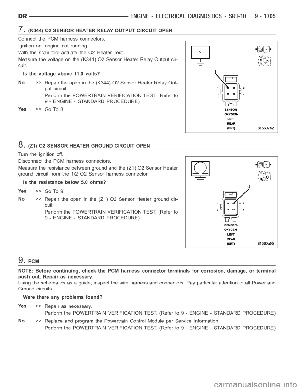
7.(K344) O2 SENSOR HEATER RELAY OUTPUT CIRCUIT OPEN
Connect the PCM harness connectors.
Ignition on, engine not running.
With the scan tool actuate the O2 Heater Test.
Measure the voltage on the (K344) O2 Sensor Heater Relay Output cir-
cuit.
Is the voltage above 11.0 volts?
No>>
Repair the open in the (K344) O2 Sensor Heater Relay Out-
put circuit.
Perform the POWERTRAIN VERIFICATION TEST. (Refer to
9 - ENGINE - STANDARD PROCEDURE)
Ye s>>
Go To 8
8.(Z1) O2 SENSOR HEATER GROUND CIRCUIT OPEN
Turn the ignition off.
Disconnect the PCM harness connectors.
Measure the resistance between ground and the (Z1) O2 Sensor Heater
ground circuit from the 1/2 O2 Sensor harness connector.
Is the resistance below 5.0 ohms?
Ye s>>
Go To 9
No>>
Repair the open in the (Z1) O2 Sensor Heater ground cir-
cuit.
Perform the POWERTRAIN VERIFICATION TEST. (Refer to
9 - ENGINE - STANDARD PROCEDURE)
9.PCM
NOTE: Before continuing, check the PCM harness connector terminals for corrosion, damage, or terminal
push out. Repair as necessary.
Using the schematics as a guide, inspect the wire harness and connectors. Pay particular attention to all Power and
Ground circuits.
Were there any problems found?
Ye s>>
Repair as necessary.
Perform the POWERTRAIN VERIFICATION TEST. (Refer to 9 - ENGINE - STANDARD PROCEDURE)
No>>
Replace and program the Powertrain Control Module per Service Information.
Perform the POWERTRAIN VERIFICATION TEST. (Refer to 9 - ENGINE - STANDARD PROCEDURE)