Page 3039 of 5267
28. Measure OD clutch pack clearance. Set up Dial
Indicator C-3339 (1) on top of the OD/Reverse
reaction plate (2).
29. Zero dial indicator and apply 30 psi (206 kPa) air
pressure to the overdrive clutch hose on Pressure
Fixture 8391. Measure and record OD clutch pack
measurement in four (4) places, 90° apart.
30. Take average of four measurements and compare
with OD clutch pack clearance specification.The
overdrive (OD) clutch pack clearance is
1.07-3.25 mm (0.042-0.128 in.).
If not within specifications,theclutchisnotassembled
properly. There is no adjustment for the OD clutch
clearance.
31. Install reverse clutch pack (two fibers/one steel)
(1, 2).
32. Install reverse clutch reaction plate (1) with the
flat side down towards reverse clutch.
Page 3040 of 5267
33. Tap reaction plate (3) down to allow installation of
the reverse clutch snap ring (1). Install reverse
clutch snap ring (1).
34. Pry up reverse reaction plate (4) to seat against
snap ring (2).
35. Set up a Dial Indicator C-3339 (1) on the reverse
clutch pack (2).
Page 3041 of 5267
36. Using moderate pressure, press down and hold
(near indicator) reverse clutch disc (2) with screw-
driver or suitable tool and zero dial indicator (1).
When releasing pressure, indicator should
advance 0.005-0.010 inches as clutch pack
relaxes.
37. Apply 30 psi (206 kPa) air pressure to the reverse
clutch hose on Pressure Fixture 8391. Measure
and record reverse clutch pack measurement in
four (4) places, 90° apart.
38. Take average of four measurements and compare
with reverse clutch pack clearance specification.
The reverse clutch pack clearance is 0.89-1.37
mm (0.035-0.054 in.).Select the proper reverse
clutch snap ring to achieve specifications.
39. To complete the assembly, reverse clutch and
overdrive clutch must be removed.
40. Install the number 2 needle bearing (1).
41. Install the underdrive shaft assembly (1).
Page 3043 of 5267
45. Reinstall overdrive and reverse clutch.Recheck-
ing these clutch clearances is not necessary.
Page 3044 of 5267

SENSOR-INPUT SPEED
DESCRIPTION
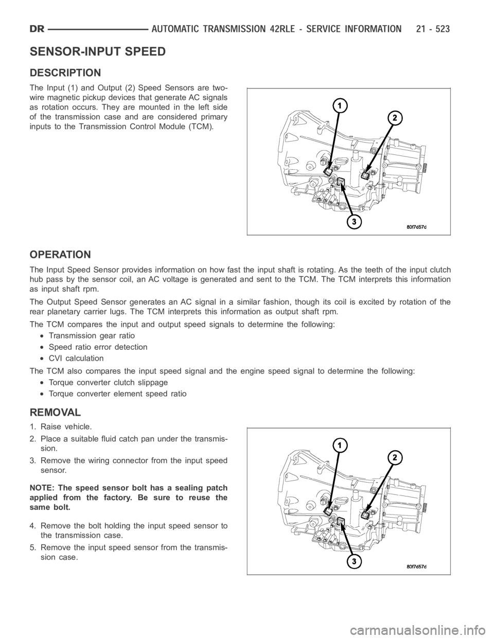
The Input (1) and Output (2) Speed Sensors are two-
wire magnetic pickup devices that generate AC signals
as rotation occurs. They are mounted in the left side
of the transmission case and are considered primary
inputs to the Transmission Control Module (TCM).
OPERATION
The Input Speed Sensor provides information on how fast the input shaft is rotating. As the teeth of the input clutch
hub pass by the sensor coil, an AC voltage is generated and sent to the TCM. The TCM interprets this information
as input shaft rpm.
The Output Speed Sensor generates an AC signal in a similar fashion, thoughitscoilisexcitedbyrotationofthe
rear planetary carrier lugs. The TCM interprets this information as outputshaftrpm.
The TCM compares the input and output speed signals to determine the following:
Transmission gear ratio
Speed ratio error detection
CVI calculation
The TCM also compares the input speed signal and the engine speed signal to determine the following:
Torque converter clutch slippage
Torque converter element speed ratio
REMOVAL
1. Raise vehicle.
2. Place a suitable fluid catch pan under the transmis-
sion.
3. Remove the wiring connector from the input speed
sensor.
NOTE: The speed sensor bolt has a sealing patch
applied from the factory. Be sure to reuse the
same bolt.
4. Remove the bolt holding the input speed sensor to
the transmission case.
5. Remove the input speed sensor from the transmis-
sion case.
Page 3051 of 5267

SENSOR-OUTPUT SPEED
DESCRIPTION
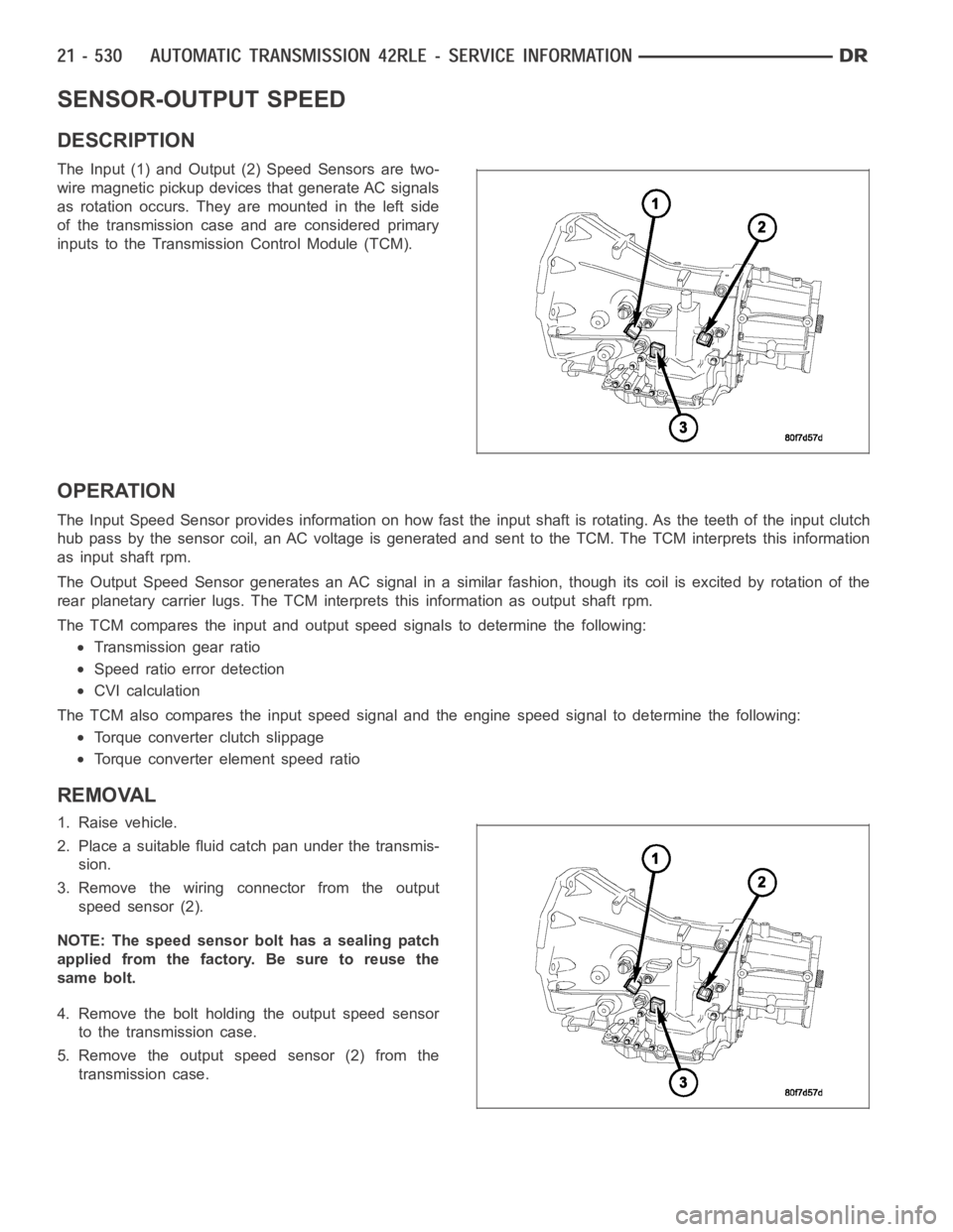
The Input (1) and Output (2) Speed Sensors are two-
wire magnetic pickup devices that generate AC signals
as rotation occurs. They are mounted in the left side
of the transmission case and are considered primary
inputs to the Transmission Control Module (TCM).
OPERATION
The Input Speed Sensor provides information on how fast the input shaft is rotating. As the teeth of the input clutch
hub pass by the sensor coil, an AC voltage is generated and sent to the TCM. The TCM interprets this information
as input shaft rpm.
The Output Speed Sensor generates an AC signal in a similar fashion, thoughitscoilisexcitedbyrotationofthe
rear planetary carrier lugs. The TCM interprets this information as outputshaftrpm.
The TCM compares the input and output speed signals to determine the following:
Transmission gear ratio
Speed ratio error detection
CVI calculation
The TCM also compares the input speed signal and the engine speed signal to determine the following:
Torque converter clutch slippage
Torque converter element speed ratio
REMOVAL
1. Raise vehicle.
2. Place a suitable fluid catch pan under the transmis-
sion.
3. Remove the wiring connector from the output
speed sensor (2).
NOTE: The speed sensor bolt has a sealing patch
applied from the factory. Be sure to reuse the
same bolt.
4. Remove the bolt holding the output speed sensor
to the transmission case.
5. Remove the output speed sensor (2) from the
transmission case.
Page 3053 of 5267
GEARTRAIN-PLANETARY
DESCRIPTION
The planetary geartrain is located between the input
clutch assembly and the rear of the transmission case.
The planetary geartrain consists of two sun gears, two
planetary carriers, two annulus (ring) gears, and one
output shaft.
OPERATION
The planetary geartrain utilizes two planetary gear setsthat connect thetransmission input shaft to the output shaft.
Input and holding clutches drive or lock different planetary members to change output ratio or direction.
Page 3058 of 5267

SOLENOID
DESCRIPTION
The typical electrical solenoid used in automotive applications is a linear actuator. It is a device that produces
motion in a straight line. This straight line motion can be either forward or backward in direction, and short or long
distance.
A solenoid is an electromechanical device that uses a magnetic force to perform work. It consists of a coil of wire,
wrapped around a magnetic core made from steel or iron, and a spring loaded,movable plunger, which performs
the work, or straight line motion.
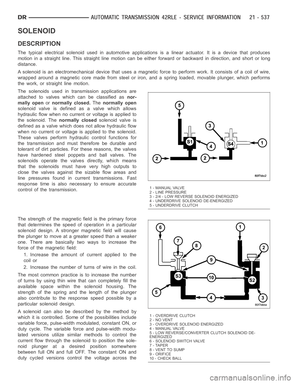
The solenoids used in transmission applications are
attached to valves which can be classified asnor-
mally openornormally closed.Thenormally open
solenoid valve is defined as a valve which allows
hydraulic flow when no current or voltage is applied to
the solenoid. Thenormally closedsolenoid valve is
defined as a valve which does not allow hydraulic flow
when no current or voltage is applied to the solenoid.
These valves perform hydraulic control functions for
the transmission and must therefore be durable and
tolerant of dirt particles. For these reasons, the valves
have hardened steel poppets and ball valves. The
solenoids operate the valves directly, which means
that the solenoids must have very high outputs to
close the valves against the sizable flow areas and
line pressures found in current transmissions. Fast
response time is also necessary to ensure accurate
control of the transmission.
The strength of the magnetic field is the primary force
that determines the speed of operation in a particular
solenoid design. A stronger magnetic field will cause
the plunger to move at a greater speed than a weaker
one. There are basically two ways to increase the
force of the magnetic field:
1. Increase the amount of current applied to the
coil or
2. Increase the number of turns of wire in the coil.
The most common practice is to increase the number
of turns by using thin wire that can completely fill the
available space within the solenoid housing. The
strength of the spring and the length of the plunger
also contribute to the response speed possible by a
particular solenoid design.
A solenoid can also be described by the method by
which it is controlled. Some of the possibilities include
variable force, pulse-width modulated, constant ON, or
duty cycle. The variable force and pulse-width modu-
lated versions utilize similar methods to control the
current flow through the solenoid to position the sole-
noid plunger at a desired position somewhere
between full ON and full OFF. The constant ON and
duty cycled versions control the voltage across the
1 - MANUAL VALVE
2 - LINE PRESSURE
3 - 2/4 - LOW REVERSE SOLENOID ENERGIZED
4 - UNDERDRIVE SOLENOID DE-ENERGIZED
5 - UNDERDRIVE CLUTCH
1-OVERDRIVECLUTCH
2 - NO VENT
3 - OVERDRIVE SOLENOID ENERGIZED
4 - MANUAL VALVE
5 - LOW REVERSE/CONVERTER CLUTCH SOLENOID DE-
ENERGIZED
6-SOLENOIDSWITCHVALVE
7 - TAPER
8 - VENT TO SUMP
9 - ORIFICE
10 - CHECK BALL