Page 437 of 5267
*NO CRANK CONDITION
For a complete wiring diagramRefer to Section 8W.
Page 442 of 5267
*NO RESPONSE WITH A NO START CONDITION
For a complete wiring diagramRefer to Section 8W.
Page 448 of 5267

*START AND STALL CONDITION
For a complete wiring diagramRefer to Section 8W.
Possible Causes
CURRENT PCM DTCS
CURRENT SKIM DTCS
THROTTLE POSITION SENSOR SWEEP
TP SENSOR NO.1 VOLTAGE GREATER THAN 0.92 VOLTS WITH THROTTLE CLOSED
ECT SENSOR
OTHER POSSIBLE CAUSES FOR START AND STALL CONDITON
FUEL CONTAMINATION
Diagnostic Test
1.CHECKING DTCS
Ignition on, engine not running.
With a scan tool, read DTCs.
Are any DTCs present?
Ye s>>
Refer to the appropriate Diagnostic Procedure.
Perform the POWERTRAIN VERIFICATION TEST. (Refer to 9 - ENGINE - STANDARD PROCEDURE)
No>>
Go To 2
2.CHECKING SKREEM DTCS
NOTE: If you are unable to communicate with the SKIM/SKREEM, refer to the VEHICLE THEFT AND SECU-
RITY ELECTRICAL DIAGNOSTICS in Section 8 and perform the appropriate diagnostics.
With the scan tool, read the SKIM codes.
Are there any SKIM DTCs?
Ye s>>
Refer to the Sentry Key Vehicle Theft Security Electrical Diagnostics in Section 8.
Perform the POWERTRAIN VERIFICATION TEST. (Refer to 9 - ENGINE - STANDARD PROCEDURE)
No>>
Go To 3
3.TP SENSOR SWEEP
Ignition on, engine not running.
With the scan tool read TP Sensor voltage.
While monitoring the scan tool, slowly open and close the Throttle on vehicles equipped with a 3.7L or 4.7L engine.
On vehicles equipped with a 5.7L engine, using a scan tool perform the pedalfollower test and monitor both TP
Sensor voltage readings.
Was the voltage change smooth?
Ye s>>
Go To 4
No>>
Replace the Throttle Position Sensor on a 3.7L and 4.7L engines or the Throttle Body Assembly on a
5.7L engine.
Perform the POWERTRAIN VERIFICATION TEST. (Refer to 9 - ENGINE - STANDARD PROCEDURE)
Page 451 of 5267

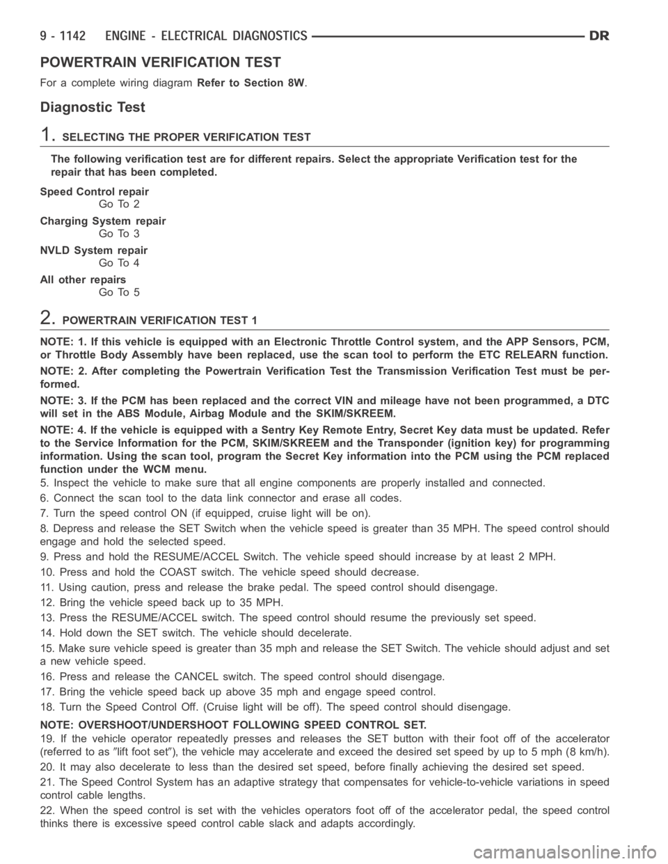
POWERTRAIN VERIFICATION TEST
For a complete wiring diagramRefer to Section 8W.
Diagnostic Test
1.SELECTING THE PROPER VERIFICATION TEST
The following verification test are for different repairs. Select the appropriate Verification test for the
repair that has been completed.
Speed Control repair
Go To 2
Charging System repair
Go To 3
NVLD System repair
Go To 4
All other repairs
Go To 5
2.POWERTRAIN VERIFICATION TEST 1
NOTE: 1. If this vehicle is equipped with an Electronic Throttle Control system, and the APP Sensors, PCM,
or Throttle Body Assembly have been replaced, use the scan tool to perform the ETC RELEARN function.
NOTE: 2. After completing the Powertrain Verification Test the Transmission Verification Test must be per-
formed.
NOTE: 3. If the PCM has been replaced and the correct VIN and mileage have notbeen programmed, a DTC
will set in the ABS Module, Airbag Module and the SKIM/SKREEM.
NOTE: 4. If the vehicle is equipped with a Sentry Key Remote Entry, Secret Key data must be updated. Refer
to the Service Information for the PCM, SKIM/SKREEM and the Transponder (ignition key) for programming
information. Using the scan tool, program the Secret Key information intothe PCM using the PCM replaced
function under the WCM menu.
5. Inspect the vehicle to make sure that all engine components are properlyinstalled and connected.
6. Connect the scan tool to the data link connector and erase all codes.
7. Turn the speed control ON (if equipped, cruise light will be on).
8. Depress and release the SET Switch when the vehicle speed is greater than35 MPH. The speed control should
engage and hold the selected speed.
9. Press and hold the RESUME/ACCEL Switch. The vehicle speed should increase by at least 2 MPH.
10. Press and hold the COAST switch. The vehicle speed should decrease.
11. Using caution, press and release the brake pedal. The speed control should disengage.
12. Bring the vehicle speed back up to 35 MPH.
13. Press the RESUME/ACCEL switch. The speed control should resume the previously set speed.
14. Hold down the SET switch. The vehicle should decelerate.
15. Make sure vehicle speed is greater than 35 mph and release the SET Switch. The vehicle should adjust and set
a new vehicle speed.
16. Press and release the CANCEL switch. The speed control should disengage.
17. Bring the vehicle speed back up above 35 mph and engage speed control.
18. Turn the Speed Control Off. (Cruise light will be off). The speed control should disengage.
NOTE: OVERSHOOT/UNDERSHOOT FOLLOWING SPEED CONTROL SET.
19. If the vehicle operator repeatedly presses and releases the SET buttonwith their foot off of the accelerator
(referred to as
lift foot set), the vehicle may accelerate and exceed the desired set speed by up to 5 mph (8km/h).
20. It may also decelerate to less than the desired set speed, before finally achieving the desired set speed.
21. The Speed Control System has an adaptive strategy that compensates forvehicle-to-vehicle variations in speed
control cable lengths.
22. When the speed control is set with the vehicles operators foot off of theaccelerator pedal, the speed control
thinks there is excessive speed control cable slack and adapts accordingly.
Page 459 of 5267

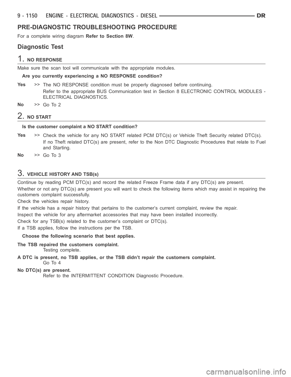
PRE-DIAGNOSTIC TROUBLESHOOTING PROCEDURE
For a complete wiring diagramRefer to Section 8W.
Diagnostic Test
1.NO RESPONSE
Make sure the scan tool will communicate with the appropriate modules.
Are you currently experiencing a NO RESPONSE condition?
Ye s>>
The NO RESPONSE condition must be properly diagnosed before continuing.
Refer to the appropriate BUS Communication test in Section 8 ELECTRONIC CONTROL MODULES -
ELECTRICAL DIAGNOSTICS.
No>>
Go To 2
2.NO START
Is the customer complaint a NO START condition?
Ye s>>
Check the vehicle for any NO START related PCM DTC(s) or Vehicle Theft Security related DTC(s).
If no Theft related DTC(s) are present, refer to the Non DTC Diagnostic Procedures that relate to Fuel
and Starting.
No>>
Go To 3
3.VEHICLE HISTORY AND TSB(s)
Continue by reading PCM DTC(s) and record the related Freeze Frame data if any DTC(s) are present.
Whether or not any DTC(s) are present you will want to check the following items which may assist in repairing the
customers complaint successfully.
Check the vehicles repair history.
If the vehicle has a repair history that pertains to the customer’s currentcomplaint, review the repair.
Inspect the vehicle for any aftermarket accessories that may have been installed incorrectly.
Check for any TSB(s) related to the customer’s complaint or DTC(s).
If a TSB applies, follow the instructions per the TSB.
Choose the following scenario that best applies.
The TSB repaired the customers complaint.
Testing complete.
A DTC is present, no TSB applies, or the TSB didn’t repair the customers complaint.
Go To 4
No DTC(s) are present.
Refer to the INTERMITTENT CONDITION Diagnostic Procedure.
Page 466 of 5267

INTERMITTENT CONDITION
For a complete wiring diagramRefer to Section 8W.
POSSIBLE CAUSES
INTERMITTENT CONDITION
Diagnostic Test
1.INTERMITTENT CONDITION
NOTE: The conditions that set the DTC are not present at this time. The following list may help in identi-
fying the intermittent condition.
WARNING: When the engine is operating, do not stand in direct line with the fan. Do not put your hands
near the pulleys, belts, or fan. Do notwear loose clothing. Failure to follow these instructions can result in
personal injury or death.
Refer to any Technical Service Bulletins (TSBs) that may apply.
Review the scan tool Freeze Frame information. If possible, try to duplicate the conditions under which the DTC set.
With the engine running at normal operating temperature, monitor the scantool parameters relatedtotheDTCwhile
wiggling the wire harness. Look for parameter values to change and/or a DTCto set.
Turn the ignition off.
Visually inspect the related wire harness. Disconnect all the related harness connectors. Look for any chafed,
pierced, pinched, partially broken wires and broken, bent, pushed out, orcorroded terminals.
Perform a voltage drop test on the related circuits between the suspected faulty component and the ECM.
Inspect and clean all ECM, engine, and chassis grounds that are related to the most current DTC.
If numerous trouble codes were set, use a wire schematic and look for any common ground or supply circuits.
For any Relay DTCs, actuate the Relay with the scan tool and wiggle the related wire harness to try to interrupt the
actuation.
For intermittent Evaporative Emission trouble codes perform a visual andphysical inspection of the related parts
including hoses and the Fuel Filler cap.
For intermittent Misfire DTC’s check for restrictions in the Intake and Exhaust system, proper installation of Sensors,
vacuum leaks, and binding components that are run by the accessory drive belt.
Use the scan tool to perform a System Test if one applies to failing component.
A co-pilot, data recorder, and/or lab scope should be used to help diagnoseintermittent conditions.
Were any problems found during the above inspections?
Ye s>>
Perform the necessary repairs.
Perform POWERTRAIN VERIFICATION TEST VER - 1 (DIESEL).
No>>
Te s t C o m p l e t e .
Page 467 of 5267
P0016-ENGINE SPEED SIGNAL MISMATCH
For a complete wiring diagramRefer to Section 8W.
Page 469 of 5267
P0069-BOOST KEY ON RATIONALITY
For a complete wiring diagramRefer to Section 8W.