Page 4936 of 5267
12.RUN THE ACTUATOR DTC DETECTION TEST
Reconnect the A/C Heater Control C1 harness connector.
Turn the ignition on.
With the scan tool in HVAC, select System Tests and then select Actuator DTCDetection. When the test is com-
plete, select View DTCs.
Does the scan tool only display: B105F–CLIMATE CONTROL MOTOR(S) COMMON 1 CONTROL CIRCUIT
LOW?
Ye s>>
Replace the A/C Heater Control in accordance with the Service Information.
Perform BODY VERIFICATION TEST – VER 1. (Refer to 8 - ELECTRICAL/ELECTRONIC CONTROL
MODULES - STANDARD PROCEDURE).
No, Other DTC(s) Displayed
Diagnose and repair the other DTC(s). If multiple DTCs are present, beginning with the passenger blend
door, diagnose and repair all short high DTCs and then all short low DTCs. Refer to the Table of Con-
tents in this Section for a complete list of HVAC related symptoms.
No, And No DTCs Displayed
Using the wiring diagram as a guide, inspect the wiring and connectors for conditions causing an inter-
mittent short. Repair as necessary.
Perform BODY VERIFICATION TEST – VER 1. (Refer to 8 - ELECTRICAL/ELECTRONIC CONTROL
MODULES - STANDARD PROCEDURE).
Page 4943 of 5267
10.RUN THE ACTUATOR DTC DETECTION TEST
Reconnect the A/C Heater Control C1 harness connector.
Turn the ignition on.
With the scan tool in HVAC, select System Tests and then select Actuator DTCDetection. When the test is com-
plete, select View DTCs.
Does the scan tool only display: B105F–CLIMATE CONTROL MOTOR(S) COMMON 1 CONTROL CIRCUIT
LOW?
Ye s>>
Replace the A/C Heater Control in accordance with the Service Information.
Perform BODY VERIFICATION TEST – VER 1. (Refer to 8 - ELECTRICAL/ELECTRONIC CONTROL
MODULES - STANDARD PROCEDURE).
No, Other DTC(s) Displayed
Diagnose and repair the other DTC(s). If multiple DTCs are present, beginning with the common circuit,
diagnose and repair all short high DTCs and then all short low DTCs. Refer tothe Table of Contents in
this Section for a complete list of HVAC related symptoms.
No, And No DTCs Displayed
Using the wiring diagram as a guide, inspect the wiring and connectors for conditions causing an inter-
mittent short. Repair as necessary.
Perform BODY VERIFICATION TEST – VER 1. (Refer to 8 - ELECTRICAL/ELECTRONIC CONTROL
MODULES - STANDARD PROCEDURE).
Page 4945 of 5267
3.CHECK FOR NORMAL A/C MODE SWITCH & STATUS INDICATOR FUNCTION
Turn the ignition on.
Turn the blower control on.
Press the A/C mode switch on and off several times while observing the A/C status indicator.
Does the A/C status indicator turn on and off with respect to the switch position?
Ye s>>
Go To 4
No>>
Replace the A/C Heater Control in accordance with the Service Information.
Perform BODY VERIFICATION TEST – VER 1. (Refer to 8 - ELECTRICAL/ELECTRONIC CONTROL
MODULES - STANDARD PROCEDURE).
4.VERIFY THAT DTC B1001–A/C SWITCH REQUEST INPUT CIRCUIT LOW IS STILL ACTIVE
Turn the blower control off.
With the scan tool, erase HVAC DTCs.
Turn the ignition off, wait 10 seconds, and then turn the ignition on. Wait two minutes before proceeding.
With the scan tool, read HVAC DTCs.
Does the scan tool display active: B1001–A/C SWITCH REQUEST INPUT CIRCUITLOW?
Ye s>>
Replace the A/C Heater Control in accordance with the Service Information.
Perform BODY VERIFICATION TEST – VER 1. (Refer to 8 - ELECTRICAL/ELECTRONIC CONTROL
MODULES - STANDARD PROCEDURE).
No>>
Perform BODY VERIFICATION TEST – VER 1. (Refer to 8 - ELECTRICAL/ELECTRONIC CONTROL
MODULES - STANDARD PROCEDURE).
Page 4947 of 5267
3.CHECK FOR NORMAL REAR DEFROST MODE SWITCH & STATUS INDICATOR FUNCTION
Turn the ignition on.
Press the Rear Defrost mode switch on and off several times while observingthe status indicator.
Does the Rear Defrost status indicator turn on and off with respect to the switch position?
Ye s>>
Go To 4
No>>
Replace the A/C Heater Control in accordance with the Service Information.
Perform BODY VERIFICATION TEST – VER 1. (Refer to 8 - ELECTRICAL/ELECTRONIC CONTROL
MODULES - STANDARD PROCEDURE).
4.VERIFY THAT DTC B1016–REAR DEFROST SWITCH REQUEST INPUT CIRCUIT LOW IS STILL ACTIVE
With the scan tool, erase HVAC DTCs.
Turn the ignition off, wait 10 seconds, and then turn the ignition on. Wait two minutes before proceeding.
With the scan tool, read HVAC DTCs.
Does the scan tool display active: B1016–REAR DEFROST SWITCH REQUEST INPUT CIRCUIT LOW?
Ye s>>
Replace the A/C Heater Control in accordance with the Service Information.
Perform BODY VERIFICATION TEST – VER 1. (Refer to 8 - ELECTRICAL/ELECTRONIC CONTROL
MODULES - STANDARD PROCEDURE).
No>>
Perform BODY VERIFICATION TEST – VER 1. (Refer to 8 - ELECTRICAL/ELECTRONIC CONTROL
MODULES - STANDARD PROCEDURE).
Page 4949 of 5267
When Monitored:
With the ignition on.
Set Condition:
If the Evaporator Temperature Sensor input is out of range toward the low voltage threshold, (A/D counts reach
low threshold of 3). This DTC has a maturing time of 5 seconds and a de-maturing time of 10 seconds. If the
DTC’s status changes from active to stored it will stay in memory for 100 ignition cycles.
Possible Causes
(C21) EVAPORATOR TEMPERATURE SENSOR SIGNAL CIRCUIT SHORTED TO GROUND
(C21) EVAPORATOR TEMPERATURE SENSOR SIGNAL CIRCUIT SHORTED TO (C121) SENSOR GROUND
CIRCUIT
EVAPORATOR TEMPERATURE SENSOR
A/C HEATER CONTROL
NOTE: This DTC must be active for the results of this test to be valid. Do not perform this test if this DTC
is stored. Refer to HVAC System Test for stored DTC test procedures.
Diagnostic Test
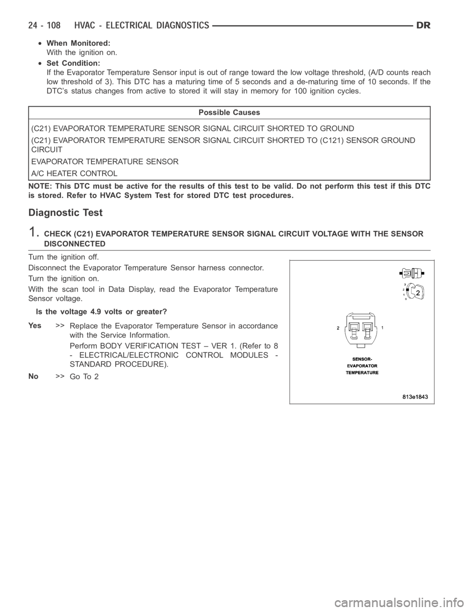
1.CHECK (C21) EVAPORATOR TEMPERATURE SENSOR SIGNAL CIRCUIT VOLTAGE WITH THE SENSOR
DISCONNECTED
Turn the ignition off.
Disconnect the Evaporator Temperature Sensor harness connector.
Turn the ignition on.
With the scan tool in Data Display, read the Evaporator Temperature
Sensor voltage.
Is the voltage 4.9 volts or greater?
Ye s>>
Replace the Evaporator Temperature Sensor in accordance
with the Service Information.
Perform BODY VERIFICATION TEST – VER 1. (Refer to 8
- ELECTRICAL/ELECTRONIC CONTROL MODULES -
STANDARD PROCEDURE).
No>>
Go To 2
Page 4953 of 5267
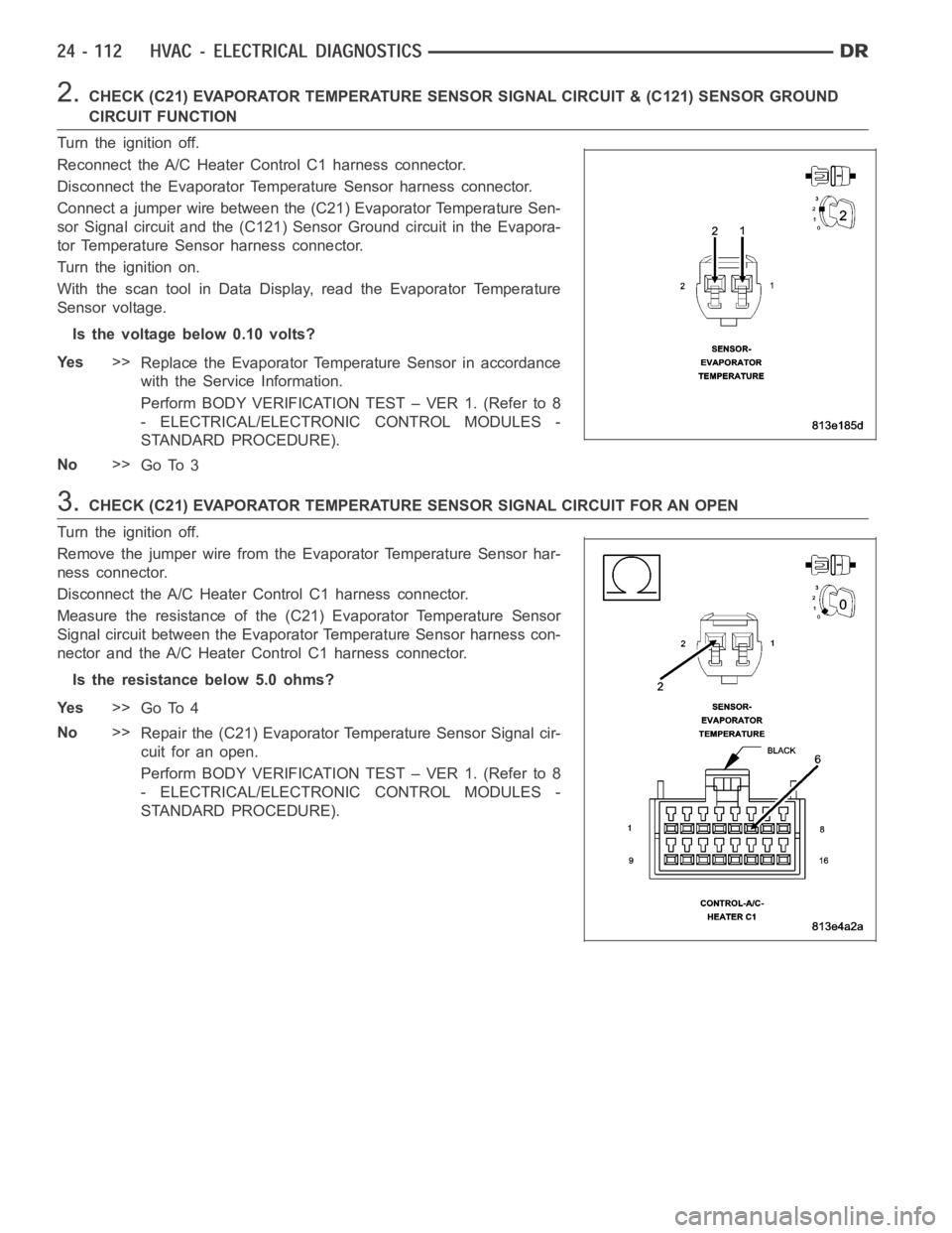
2.CHECK (C21) EVAPORATOR TEMPERATURE SENSOR SIGNAL CIRCUIT & (C121) SENSORGROUND
CIRCUIT FUNCTION
Turn the ignition off.
Reconnect the A/C Heater Control C1 harness connector.
Disconnect the Evaporator Temperature Sensor harness connector.
Connect a jumper wire between the (C21) Evaporator Temperature Sen-
sor Signal circuit and the (C121) Sensor Ground circuit in the Evapora-
tor Temperature Sensor harness connector.
Turn the ignition on.
With the scan tool in Data Display, read the Evaporator Temperature
Sensor voltage.
Is the voltage below 0.10 volts?
Ye s>>
Replace the Evaporator Temperature Sensor in accordance
with the Service Information.
Perform BODY VERIFICATION TEST – VER 1. (Refer to 8
- ELECTRICAL/ELECTRONIC CONTROL MODULES -
STANDARD PROCEDURE).
No>>
Go To 3
3.CHECK (C21) EVAPORATOR TEMPERATURE SENSOR SIGNAL CIRCUIT FOR AN OPEN
Turn the ignition off.
Remove the jumper wire from the Evaporator Temperature Sensor har-
ness connector.
Disconnect the A/C Heater Control C1 harness connector.
Measure the resistance of the (C21) Evaporator Temperature Sensor
Signal circuit between the Evaporator Temperature Sensor harness con-
nector and the A/C Heater Control C1 harness connector.
Is the resistance below 5.0 ohms?
Ye s>>
Go To 4
No>>
Repair the (C21) Evaporator Temperature Sensor Signal cir-
cuit for an open.
Perform BODY VERIFICATION TEST – VER 1. (Refer to 8
- ELECTRICAL/ELECTRONIC CONTROL MODULES -
STANDARD PROCEDURE).
Page 4959 of 5267
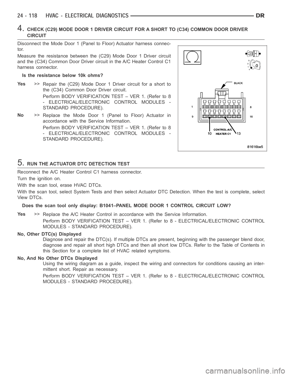
4.CHECK (C29) MODE DOOR 1 DRIVER CIRCUIT FOR A SHORT TO (C34) COMMON DOOR DRIVER
CIRCUIT
Disconnect the Mode Door 1 (Panel to Floor) Actuator harness connec-
tor.
Measure the resistance between the (C29) Mode Door 1 Driver circuit
and the (C34) Common Door Driver circuit in the A/C Heater Control C1
harness connector.
Istheresistancebelow10kohms?
Ye s>>
Repair the (C29) Mode Door 1 Driver circuit for a short to
the (C34) Common Door Driver circuit.
Perform BODY VERIFICATION TEST – VER 1. (Refer to 8
- ELECTRICAL/ELECTRONIC CONTROL MODULES -
STANDARD PROCEDURE).
No>>
Replace the Mode Door 1 (Panel to Floor) Actuator in
accordance with the Service Information.
Perform BODY VERIFICATION TEST – VER 1. (Refer to 8
- ELECTRICAL/ELECTRONIC CONTROL MODULES -
STANDARD PROCEDURE).
5.RUN THE ACTUATOR DTC DETECTION TEST
Reconnect the A/C Heater Control C1 harness connector.
Turn the ignition on.
With the scan tool, erase HVAC DTCs.
With the scan tool, select System Tests and then select Actuator DTC Detection. When the test is complete, select
View DTCs.
Does the scan tool only display: B1041–PANEL MODE DOOR 1 CONTROL CIRCUIT LOW?
Ye s>>
Replace the A/C Heater Control in accordance with the Service Information.
Perform BODY VERIFICATION TEST – VER 1. (Refer to 8 - ELECTRICAL/ELECTRONIC CONTROL
MODULES - STANDARD PROCEDURE).
No, Other DTC(s) Displayed
Diagnose and repair the DTC(s). If multiple DTCs are present, beginning with the passenger blend door,
diagnose and repair all short high DTCs and then all short low DTCs. Refer tothe Table of Contents in
this Section for a complete list of HVAC related symptoms.
No, And No Other DTCs Displayed
Using the wiring diagram as a guide, inspect the wiring and connectors for conditions causing an inter-
mittent short. Repair as necessary.
Perform BODY VERIFICATION TEST – VER 1. (Refer to 8 - ELECTRICAL/ELECTRONIC CONTROL
MODULES - STANDARD PROCEDURE).
Page 4963 of 5267
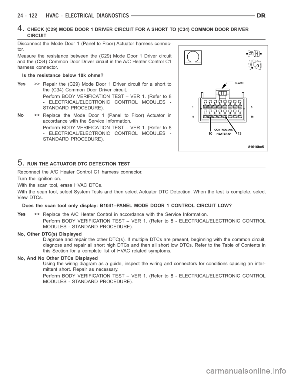
4.CHECK (C29) MODE DOOR 1 DRIVER CIRCUIT FOR A SHORT TO (C34) COMMON DOOR DRIVER
CIRCUIT
Disconnect the Mode Door 1 (Panel to Floor) Actuator harness connec-
tor.
Measure the resistance between the (C29) Mode Door 1 Driver circuit
and the (C34) Common Door Driver circuit in the A/C Heater Control C1
harness connector.
Istheresistancebelow10kohms?
Ye s>>
Repair the (C29) Mode Door 1 Driver circuit for a short to
the (C34) Common Door Driver circuit.
Perform BODY VERIFICATION TEST – VER 1. (Refer to 8
- ELECTRICAL/ELECTRONIC CONTROL MODULES -
STANDARD PROCEDURE).
No>>
Replace the Mode Door 1 (Panel to Floor) Actuator in
accordance with the Service Information.
Perform BODY VERIFICATION TEST – VER 1. (Refer to 8
- ELECTRICAL/ELECTRONIC CONTROL MODULES -
STANDARD PROCEDURE).
5.RUN THE ACTUATOR DTC DETECTION TEST
Reconnect the A/C Heater Control C1 harness connector.
Turn the ignition on.
With the scan tool, erase HVAC DTCs.
With the scan tool, select System Tests and then select Actuator DTC Detection. When the test is complete, select
View DTCs.
Does the scan tool only display: B1041–PANEL MODE DOOR 1 CONTROL CIRCUIT LOW?
Ye s>>
Replace the A/C Heater Control in accordance with the Service Information.
Perform BODY VERIFICATION TEST – VER 1. (Refer to 8 - ELECTRICAL/ELECTRONIC CONTROL
MODULES - STANDARD PROCEDURE).
No, Other DTC(s) Displayed
Diagnose and repair the other DTC(s). If multiple DTCs are present, beginning with the common circuit,
diagnose and repair all short high DTCs and then all short low DTCs. Refer tothe Table of Contents in
this Section for a complete list of HVAC related symptoms.
No, And No Other DTCs Displayed
Using the wiring diagram as a guide, inspect the wiring and connectors for conditions causing an inter-
mittent short. Repair as necessary.
Perform BODY VERIFICATION TEST – VER 1. (Refer to 8 - ELECTRICAL/ELECTRONIC CONTROL
MODULES - STANDARD PROCEDURE).